CN211531521U - Electromechanical device protector - Google Patents
Electromechanical device protector Download PDFInfo
- Publication number
- CN211531521U CN211531521U CN202020108605.3U CN202020108605U CN211531521U CN 211531521 U CN211531521 U CN 211531521U CN 202020108605 U CN202020108605 U CN 202020108605U CN 211531521 U CN211531521 U CN 211531521U
- Authority
- CN
- China
- Prior art keywords
- fixedly connected
- mounting
- push rod
- fixed
- shell
- Prior art date
- Legal status (The legal status is an assumption and is not a legal conclusion. Google has not performed a legal analysis and makes no representation as to the accuracy of the status listed.)
- Expired - Fee Related
Links
Images

Landscapes
- Cooling Or The Like Of Electrical Apparatus (AREA)
Abstract
The utility model belongs to the technical field of electromechanical equipment, in particular to an electromechanical equipment protection device, which comprises a shell and a support, wherein a mounting plate is fixed on the top of the shell in a threaded manner, and two symmetrically distributed screw rods are fixed on the mounting plate in a threaded manner; press down two installation pieces at casing both ends to the recess during installation, pressing down the in-process that descends, the stopper contacts the fixture block, the direction through the stopper makes the push rod receive the extrusion of fixture block, compression spring between push rod and the mount table contracts because of the extrusion this moment, be located the bottom of fixture block until the stopper, compression spring between push rod and the mount table rebounds this moment, push rod and stopper receive the spacing of fixture block this moment, make the installation piece can't deviate from among the recess, accomplish the installation, the staff presses the push rod through the auxiliary rod during dismantlement, make the compression spring between push rod and the mount table contract once more, then upwards stimulate the messenger installation piece with the casing and deviate from the recess, accomplish the dismantlement to the casing.
Description
Technical Field
The utility model belongs to the technical field of electromechanical device, concretely relates to electromechanical device protector.
Background
The electromechanical equipment generally refers to machinery, electrical equipment and electrical automation equipment, and in a building, the machinery and pipeline equipment except for earthwork, woodwork, reinforcing steel bars and muddy water are generally called, the mechanical equipment is different from hardware, and the mechanical equipment and the pipeline equipment can be finished products with certain functions.
In order to ensure the protective performance of electromechanical equipment such as a motor and an engine, a protective shell is installed outside a plurality of electromechanical equipment at present, but the protective shell is mostly installed in a screw joint fixing mode or a direct welding mode, so that when the electromechanical equipment breaks down and needs to be maintained and debugged, the protective shell is detached and installed again, time is consumed, and the maintenance efficiency is affected.
SUMMERY OF THE UTILITY MODEL
The utility model provides an electromechanical device protector to solve the problem of proposing among the above-mentioned background art.
In order to achieve the above object, the utility model provides a following technical scheme: an electromechanical equipment protection device comprises a shell and a support, wherein a mounting plate is fixed on the top of the shell in a screwed manner, two symmetrically distributed screw rods are fixed on the mounting plate in a screwed manner, the two screw rods penetrate through the mounting plate, a heat radiation fan is fixedly connected to the central position of the mounting plate, the heat radiation fan is electrically connected with an external power supply, the support is detachably connected with the shell, the support is provided with two symmetrically distributed grooves, two ends of the bottom of the shell are fixedly connected with mounting blocks, the inner wall of each mounting block is fixedly connected with a partition plate, two sides of the outer wall of the partition plate are fixedly connected with mounting tables, push rods are slidably connected in the two mounting tables, each push rod is fixedly connected with a limiting block, the top of one limiting block is fixedly connected with an auxiliary rod, the two push rods are clamped and fixed in, and a heat dissipation screen is fixedly connected to one side wall of the shell.
Preferably, the equal fixedly connected with in inner wall both sides of casing places the piece, the mounting panel through two screws with it is fixed to place a spiro union.
Preferably, the mounting plate with place the piece and all seted up two matched with thread grooves, the screw with the thread groove spiro union is fixed.
Preferably, two threaded holes are formed in the mounting plate, the two threaded rods are respectively fixed with the two threaded holes in a threaded manner, and the two threaded rods are located at one end, in the shell, of the fixing block fixedly connected with.
Preferably, the inner walls of the two grooves are fixedly connected with two clamping blocks which are symmetrically distributed.
Preferably, the mounting table and the push rod are elastically connected through a compression spring.
Preferably, through grooves are formed in the two ends of the mounting block, and the two push rods are connected with the two through grooves in a sliding mode respectively.
Compared with the prior art, the beneficial effects of the utility model are that:
press down two installation pieces at casing both ends to the recess during installation, pressing down the in-process that descends, the stopper contacts the fixture block, the direction through the stopper makes the push rod receive the extrusion of fixture block, compression spring between push rod and the mount table contracts because of the extrusion this moment, be located the bottom of fixture block until the stopper, compression spring between push rod and the mount table rebounds this moment, push rod and stopper receive the spacing of fixture block this moment, make the installation piece can't deviate from among the recess, accomplish the installation, only need the staff to press the push rod through the auxiliary rod during dismantlement, make the compression spring between push rod and the mount table contract once more, then upwards stimulate the casing and make the installation piece deviate from in the recess, accomplish the dismantlement to the casing, this scheme installation and dismantlement mode are simple, can improve the efficiency when installing and dismantling the casing, thereby the going on of the maintenance work of being more convenient for.
Drawings
The accompanying drawings are included to provide a further understanding of the invention, and are incorporated in and constitute a part of this specification, illustrate embodiments of the invention, and together with the description serve to explain the invention and not to limit the invention. In the drawings:
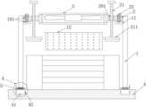
fig. 1 is a schematic structural view of the present invention;
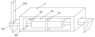
FIG. 2 is a schematic structural view of the mounting block of the present invention;
FIG. 3 is an enlarged view of portion A of FIG. 1;
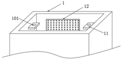
fig. 4 is a schematic structural diagram of the middle housing of the present invention.
In the figure: 1. a housing; 101. a thread groove; 11. placing the blocks; 12. a heat dissipation screen plate; 2. mounting a plate; 201. a threaded hole; 21. a screw; 211. a fixed block; 22. a screw; 3. a heat radiation fan; 4. a support; 41. a groove; 42. a clamping block; 5. mounting blocks; 501. a through groove; 502. a compression spring; 51. a partition plate; 52. an installation table; 53. a push rod; 531. a limiting block; 532. an auxiliary lever.
Detailed Description
The technical solutions in the embodiments of the present invention will be described clearly and completely with reference to the accompanying drawings in the embodiments of the present invention, and it is obvious that the described embodiments are only some embodiments of the present invention, not all embodiments. Based on the embodiments in the present invention, all other embodiments obtained by a person skilled in the art without creative work belong to the protection scope of the present invention.
Referring to fig. 1-4, the present invention provides the following technical solutions: the electromechanical equipment protection device comprises a shell 1 and a support 4, wherein the top of the shell 1 is fixedly provided with an installation plate 2 in a threaded manner; specifically, both sides of the inner wall of the shell 1 are fixedly connected with placing blocks 11, and the mounting plate 2 is fixed with the placing blocks 11 through two screws 22 in a threaded manner; specifically, the mounting plate 2 and the placing block 11 are both provided with two matched thread grooves 101, and the screw 22 is fixed with the thread grooves 101 in a threaded manner; the mounting plate 2 is placed at the upper ends of the two placing blocks 11, then the screws 22 are inserted into the thread grooves 101 formed in the mounting plate 2 and rotated, the screws 22 are enabled to take up threads to affect the threads to penetrate through the thread grooves 101 formed in the mounting plate 2 and enter the thread grooves 101 formed in the placing blocks 11, the mounting plate 2 is mounted, after the mounting plate 2 is mounted, the heat dissipation fan 3 (model YWF-200) is started to dissipate heat of electromechanical equipment located in the shell 1 through the heat dissipation fan 3, when the mounting plate 2 is dismounted, the screws 22 are rotated in the opposite direction, the screws 22 are enabled to be separated from the thread grooves 101, the mounting plate 2 is released from being positioned, and at the moment, the mounting plate 2 can be dismounted.
Referring to fig. 1, two screws 21 are fixed to an installation plate 2 in a threaded manner, the screws 21 both penetrate through the installation plate 2, a heat dissipation fan 3 is fixedly connected to the center of the installation plate 2, and the heat dissipation fan 3 is electrically connected to an external power supply; specifically, the mounting plate 2 is provided with two threaded holes 201, the two screws 21 are respectively screwed and fixed with the two threaded holes 201, and one ends of the two screws 21 located in the shell 1 are fixedly connected with fixing blocks 211; after the mounting plate 2 is mounted, the screw 21 of the threaded hole 201 is screwed clockwise, so that the screw 21 moves downwards under the influence of the threads of the threaded hole 201 until the fixing block 211 contacts the equipment, the equipment is pushed and fixed, and the stability of the equipment placed on the upper end of the support 4 is improved.
Referring to fig. 2 and 3, a support 4 is detachably connected with a housing 1, the support 4 is provided with two symmetrically distributed grooves 41, two ends of the bottom of the housing 1 are both fixedly connected with mounting blocks 5, the inner walls of the mounting blocks 5 are fixedly connected with partition plates 51, two sides of the outer wall of each partition plate 51 are both fixedly connected with mounting tables 52, and push rods 53 are slidably connected in the two mounting tables 52; specifically, the inner walls of the two grooves 41 are fixedly connected with two clamping blocks 42 which are symmetrically distributed; specifically, the mounting table 52 is elastically connected with the push rod 53 through a compression spring 502; specifically, through grooves 501 are formed in both ends of the mounting block 5, and the two push rods 53 are slidably connected with the two through grooves 501 respectively; the partition plate 51 is used for fixedly mounting the mounting table 52, and the through groove 501 is used for sliding the push rod 53, so that the push rod 53 is not blocked by the mounting block 5; when in installation, the two installation blocks 5 at the two ends of the shell 1 are aligned with the groove 41, then the installation blocks 5 are pressed into the groove 41, when the limiting block 531 contacts the fixture block 42 during pressing, the limiting block 531 plays a role in guiding, push rod 53 is extruded by the outer wall of fixture block 42 when descending through the direction of limiting block 531, compression spring 502 between push rod 53 and mount table 52 contracts because of the extrusion of the outer wall of fixture block 42 at this moment, until limiting block 531 is located the bottom of fixture block 42 and no longer contacts with the outer wall of fixture block 42, make push rod 53 no longer receive the extrusion of fixture block 42, compression spring 502 between push rod 53 and mount table 52 rebounds this moment, drive push rod 53 and limiting block 531 to promote to the normal position, make the distance between two limiting blocks 531 increase, push rod 53 and limiting block 531 receive the spacing of top fixture block 42 this moment, make mounting block 5 can't deviate from among recess 41, accomplish the installation to casing 1.
Referring to fig. 3, the two push rods 53 are both fixedly connected with a limiting block 531, the top of one limiting block 531 is fixedly connected with an auxiliary rod 532, and the two push rods 53 are fastened and fixed in the groove 41; when the shell 1 is disassembled, a human hand is only needed to press the push rod 53 through the auxiliary rod 532, the compression spring 502 between the push rod 53 and the mounting table 52 is contracted by the force of the human hand pressing the auxiliary rod 532, the distance between the two limit blocks 531 is reduced, the push rod 53 and the limit blocks 531 are no longer limited by the upper fixture block 42, the shell 1 is pulled upwards to enable the mounting block 5 to be separated from the groove 41, and the disassembly of the shell 1 is completed.
Referring to fig. 4, a heat dissipation screen 12 is fixedly connected to a side wall of the housing 1; the heat radiation screen 12 is used for discharging air blown by the heat radiation fan 3 to circulate air in the casing 1.
The utility model discloses a theory of operation and use flow: when the electromechanical device is installed, the electromechanical device is firstly placed at the upper end of the support 4, the two mounting blocks 5 at the two ends of the shell 1 are aligned with the groove 41, then the mounting blocks 5 are pressed into the groove 41, the limiting block 531 contacts the clamping block 42 during pressing, the limiting block 531 plays a guiding role, the push rod 53 is pressed by the outer wall of the clamping block 42 during descending through the guiding of the limiting block 531, at the moment, the compression spring 502 between the push rod 53 and the mounting table 52 is contracted due to the extrusion of the outer wall of the clamping block 42 until the limiting block 531 is positioned at the bottom of the clamping block 42 and is not contacted with the outer wall of the clamping block 42, the push rod 53 is not pressed by the clamping block 42 any more, at the moment, the compression spring 502 between the push rod 53 and the mounting table 52 rebounds to drive the push rod 53 and the limiting block 531 to be pushed to the original position, the distance between the two limiting blocks 531 is increased, at the, completing the installation of the shell 1, then placing the mounting plate 2 at the upper ends of the two placing blocks 11, inserting the screw 22 into the thread groove 101 formed in the mounting plate 2 and rotating, enabling the screw 22 to pass through the thread groove 101 formed in the mounting plate 2 under the thread effect and enter the thread groove 101 formed in the placing block 11, completing the installation of the mounting plate 2, after the mounting plate 2 is installed, clockwise screwing the screw 21 of the thread hole 201, enabling the screw 21 to move downwards under the thread effect of the thread hole 201 until the fixing block 211 contacts the equipment, pushing and fixing the equipment, then starting the heat dissipation fan 3 to dissipate heat of the electromechanical equipment positioned in the shell 1 through the heat dissipation fan 3, enabling the heat dissipation screen 12 to be used for discharging air blown out by the heat dissipation fan 3, enabling the air in the shell 1 to circulate, and when maintaining the electromechanical equipment in the shell 1, pressing the push rod 53 through the auxiliary rod 532 by hands, make compression spring 502 between push rod 53 and the mount table 52 receive the power shrink of the staff's pressing auxiliary rod 532, the distance between two stopper 531 reduces this moment, push rod 53 and stopper 531 no longer receive the spacing of top fixture block 42, upwards stimulate casing 1 and make installation piece 5 deviate from recess 41, accomplish the dismantlement to casing 1, can maintain the electromechanical device of support 4 upper end this moment, this scheme installation and dismantlement mode are simple, efficiency when can improving casing 1 installation and dismantlement, thereby the going on of maintenance work of being more convenient for.
In the description of the present invention, it should be noted that the terms "vertical", "upper", "lower", "horizontal", and the like indicate orientations or positional relationships based on the orientations or positional relationships shown in the drawings, and are only for convenience of description and simplification of description, but do not indicate or imply that the device or element referred to must have a specific orientation, be constructed in a specific orientation, and be operated, and thus should not be construed as limiting the present invention.
In the description of the present invention, it should also be noted that, unless otherwise explicitly specified or limited, the terms "disposed," "mounted," "connected," and "connected" are to be construed broadly, e.g., as meaning either a fixed connection, a removable connection, or an integral connection; can be mechanically or electrically connected; they may be connected directly or indirectly through intervening media, or they may be interconnected between two elements. The specific meaning of the above terms in the present invention can be understood according to specific situations by those skilled in the art.
Finally, it should be noted that: although the present invention has been described in detail with reference to the foregoing embodiments, it will be apparent to those skilled in the art that modifications may be made to the embodiments described in the foregoing embodiments, or equivalents may be substituted for elements thereof. Any modification, equivalent replacement, or improvement made within the spirit and principle of the present invention should be included in the protection scope of the present invention.
Claims (7)
1. An electromechanical device protection device comprising a housing (1) and a support (4), characterized in that: the mounting plate (2) is fixed to the top of the shell (1) through a threaded connection, the mounting plate (2) through a threaded connection is fixed with two symmetrically distributed screw rods (21), the two screw rods (21) penetrate through the mounting plate (2), the central position of the mounting plate (2) is fixedly connected with a cooling fan (3), the cooling fan (3) is electrically connected with an external power supply, the support (4) is detachably connected with the shell (1), the support (4) is provided with two symmetrically distributed grooves (41), two ends of the bottom of the shell (1) are fixedly connected with mounting blocks (5), a partition plate (51) is fixedly connected to the inner wall of each mounting block (5), mounting platforms (52) are fixedly connected to two sides of the outer wall of each partition plate (51), push rods (53) are slidably connected in the two mounting platforms (52), and limit blocks (531) are fixedly connected to the push rods (53), the top of one of the limiting blocks (531) is fixedly connected with an auxiliary rod (532), the two push rods (53) are clamped and fixed in the groove (41), and one side wall of the shell (1) is fixedly connected with a heat dissipation screen plate (12).
2. An electromechanical device shielding device in accordance with claim 1, wherein: the equal fixedly connected with in inner wall both sides of casing (1) places piece (11), mounting panel (2) through two screws (22) with it is fixed to place piece (11) spiro union.
3. An electromechanical device shielding device in accordance with claim 2, wherein: the mounting panel (2) with place piece (11) and all seted up two matched with thread groove (101), screw (22) with thread groove (101) spiro union is fixed.
4. An electromechanical device shielding device in accordance with claim 1, wherein: two screw holes (201) have been seted up in mounting panel (2), two screw rod (21) respectively with two screw hole (201) spiro union is fixed, two screw rod (21) are located one end fixedly connected with fixed block (211) in casing (1).
5. An electromechanical device shielding device in accordance with claim 1, wherein: the inner walls of the two grooves (41) are fixedly connected with two clamping blocks (42) which are symmetrically distributed.
6. An electromechanical device shielding device in accordance with claim 1, wherein: the mounting table (52) and the push rod (53) are elastically connected through a compression spring (502).
7. An electromechanical device shielding device in accordance with claim 1, wherein: through grooves (501) are formed in two ends of the mounting block (5), and the push rods (53) are connected with the through grooves (501) in a sliding mode respectively.
Priority Applications (1)
| Application Number | Priority Date | Filing Date | Title |
|---|---|---|---|
| CN202020108605.3U CN211531521U (en) | 2020-01-18 | 2020-01-18 | Electromechanical device protector |
Applications Claiming Priority (1)
| Application Number | Priority Date | Filing Date | Title |
|---|---|---|---|
| CN202020108605.3U CN211531521U (en) | 2020-01-18 | 2020-01-18 | Electromechanical device protector |
Publications (1)
| Publication Number | Publication Date |
|---|---|
| CN211531521U true CN211531521U (en) | 2020-09-18 |
Family
ID=72459340
Family Applications (1)
| Application Number | Title | Priority Date | Filing Date |
|---|---|---|---|
| CN202020108605.3U Expired - Fee Related CN211531521U (en) | 2020-01-18 | 2020-01-18 | Electromechanical device protector |
Country Status (1)
| Country | Link |
|---|---|
| CN (1) | CN211531521U (en) |
Cited By (3)
| Publication number | Priority date | Publication date | Assignee | Title |
|---|---|---|---|---|
| CN113507810A (en) * | 2021-09-09 | 2021-10-15 | 凯瑞电子(诸城)有限公司 | Combined electronic element shell |
| CN113905574A (en) * | 2021-10-12 | 2022-01-07 | 国家电网有限公司客户服务中心 | Server placer |
| CN114295870A (en) * | 2021-12-30 | 2022-04-08 | 湖州沃宏机械自动化有限公司 | Continuous power distribution cabinet electrical variable measuring equipment |
-
2020
- 2020-01-18 CN CN202020108605.3U patent/CN211531521U/en not_active Expired - Fee Related
Cited By (4)
| Publication number | Priority date | Publication date | Assignee | Title |
|---|---|---|---|---|
| CN113507810A (en) * | 2021-09-09 | 2021-10-15 | 凯瑞电子(诸城)有限公司 | Combined electronic element shell |
| CN113507810B (en) * | 2021-09-09 | 2021-11-30 | 凯瑞电子(诸城)有限公司 | Combined electronic element shell |
| CN113905574A (en) * | 2021-10-12 | 2022-01-07 | 国家电网有限公司客户服务中心 | Server placer |
| CN114295870A (en) * | 2021-12-30 | 2022-04-08 | 湖州沃宏机械自动化有限公司 | Continuous power distribution cabinet electrical variable measuring equipment |
Similar Documents
| Publication | Publication Date | Title |
|---|---|---|
| CN211531521U (en) | Electromechanical device protector | |
| CN204400414U (en) | A kind of elevator counterweight block | |
| CN210201206U (en) | Convenient electric power cabinet of dismantling | |
| CN210350797U (en) | Reactive power compensation device convenient to dismouting | |
| CN209593656U (en) | Frame for exchanger | |
| CN214543146U (en) | Wall-hanging emergency lighting block terminal with dustproof function | |
| CN212484817U (en) | LED display screen module of quick installation | |
| CN215491604U (en) | A accurate installation appurtenance for UCMO test | |
| CN214254040U (en) | Dry-type transformer support | |
| CN209891432U (en) | Detachable board room assembling board convenient to splice | |
| CN216213141U (en) | Intelligent relay protector for electric power and with high-efficiency, safe and stable work | |
| CN211083330U (en) | Assembling and disassembling mechanism of Zigbee communication module of transformer substation | |
| CN214219975U (en) | Connecting assembly for rotary tower body and upper support | |
| CN216345664U (en) | Lighting device for exhibition hall | |
| CN219873833U (en) | Battery module and energy supply equipment thereof | |
| CN214960675U (en) | Building electrical cabinet convenient to heat dissipation | |
| CN216598542U (en) | Distribution network electrical cabinet | |
| CN212751904U (en) | Wireless charging module | |
| CN216929264U (en) | Incoming line cabinet structure convenient to dismouting | |
| CN217470641U (en) | Building electric heat dissipation equipment | |
| CN215733497U (en) | Power factor controller convenient to equipment | |
| CN217562247U (en) | Solid state hard drives that heat dissipation is good | |
| CN216145975U (en) | High-voltage board device easy to assemble | |
| CN215891856U (en) | Remove line and hang convenient to motor maintenance | |
| CN210693190U (en) | Power distribution cabinet convenient to disassemble and assemble |
Legal Events
| Date | Code | Title | Description |
|---|---|---|---|
| GR01 | Patent grant | ||
| GR01 | Patent grant | ||
| CF01 | Termination of patent right due to non-payment of annual fee |
Granted publication date: 20200918 Termination date: 20210118 |
|
| CF01 | Termination of patent right due to non-payment of annual fee |