CN216929264U - Incoming line cabinet structure convenient to dismouting - Google Patents
Incoming line cabinet structure convenient to dismouting Download PDFInfo
- Publication number
- CN216929264U CN216929264U CN202220135299.1U CN202220135299U CN216929264U CN 216929264 U CN216929264 U CN 216929264U CN 202220135299 U CN202220135299 U CN 202220135299U CN 216929264 U CN216929264 U CN 216929264U
- Authority
- CN
- China
- Prior art keywords
- curb plate
- hole
- cabinet main
- inlet wire
- structure convenient
- Prior art date
- Legal status (The legal status is an assumption and is not a legal conclusion. Google has not performed a legal analysis and makes no representation as to the accuracy of the status listed.)
- Active
Links
- 230000001681 protective effect Effects 0.000 claims abstract description 28
- 230000000694 effects Effects 0.000 claims description 17
- 230000017525 heat dissipation Effects 0.000 abstract description 5
- 238000000034 method Methods 0.000 description 6
- 238000009434 installation Methods 0.000 description 5
- 230000002411 adverse Effects 0.000 description 1
- 230000009286 beneficial effect Effects 0.000 description 1
- 230000007547 defect Effects 0.000 description 1
- 238000001125 extrusion Methods 0.000 description 1
- 238000004519 manufacturing process Methods 0.000 description 1
- 238000012986 modification Methods 0.000 description 1
- 230000004048 modification Effects 0.000 description 1
Images


Landscapes
- Road Paving Structures (AREA)
Abstract
The utility model discloses a wire inlet cabinet structure convenient to disassemble and assemble, which comprises a wire inlet cabinet main body, wherein a first protective door is arranged on the outer surface of one end of the wire inlet cabinet main body, a second protective door is arranged on the outer surface of the other end of the wire inlet cabinet main body, mounting grooves are formed in the outer surfaces of two sides of the wire inlet cabinet main body, side plates are arranged inside the mounting grooves, a clamping assembly is arranged between each side plate and the wire inlet cabinet main body, each side plate is detachably connected with the wire inlet cabinet main body through the clamping assembly, a heat dissipation assembly is arranged in the middle of each side plate, and limiting holes are formed in four corners of each mounting groove. According to the incoming line cabinet structure convenient to disassemble and assemble, the movable block is pressed downwards and slides along the sliding groove, so that the upper part of the limiting rod enters the through hole, then the side plate is clamped into the mounting groove, the movable block is loosened, and due to the reset action of the telescopic spring, the limiting rod is inserted into the limiting hole, the mounting is completed, and the incoming line cabinet structure is convenient to disassemble.
Description
Technical Field
The utility model relates to the technical field of incoming line cabinets, in particular to an incoming line cabinet structure convenient to disassemble and assemble.
Background
Present manufacturing enterprise and power supply management all need use a large amount of inlet wire cabinets or control box etc. for lay various control switch, a motor, generator or other controlgear, generally can have the generating line room in the inlet wire cabinet, overvoltage device room, relay instrument room, isolator, circuit breaker room etc. however, current inlet wire cabinet generally is double door structure, when overhauing, sometimes need open inlet wire cabinet's curb plate, increase the space of operation, however, curb plate among the prior art when the installation, generally through the fixed screw fixed, or curb plate and main part integrated into one piece, be not convenient for the dismouting, certain adverse effect has been brought for people's use, for this reason, we provide an inlet wire cabinet structure convenient to dismouting.
SUMMERY OF THE UTILITY MODEL
Technical problem to be solved
Aiming at the defects of the prior art, the utility model provides the incoming line cabinet structure convenient to disassemble and assemble, which has the advantages of convenience in disassembling and assembling between the side plates and the incoming line cabinet main body, convenience in disassembling and assembling and the like, and can effectively solve the problems in the background art.
(II) technical scheme
In order to realize the purpose, the utility model adopts the technical scheme that: the utility model provides an inlet wire cabinet structure convenient to dismouting, includes the inlet wire cabinet main part, the one end surface of inlet wire cabinet main part is provided with first guard gate, the other end surface of inlet wire cabinet main part is provided with second guard gate, the mounting groove has been seted up to the both sides surface of inlet wire cabinet main part, the inside of mounting groove is provided with the curb plate, be provided with the joint subassembly between curb plate and the inlet wire cabinet main part, the curb plate passes through the joint subassembly and can dismantle with the inlet wire cabinet main part and be connected, the middle part of curb plate is provided with radiator unit, spacing hole has been seted up in the four corners of mounting groove, just be the joint between curb plate and the mounting groove.
Preferably, the radiating assembly comprises a radiating groove, a protective net and a protective frame, the radiating groove is arranged in the middle of the side plate, the protective frame is fixedly installed on the outer surface of one side of the side plate and located inside the protective frame, the protective net is fixedly installed on the outer surface of one side of the protective frame, a fixing screw is arranged between the protective frame and the side plate, and the protective frame is fixedly connected with the side plate through the fixing screw.
Preferably, the joint subassembly includes slide opening, first activity chamber, expanding spring, dead lever, second activity chamber, spout, movable block, through-hole and gag lever post, just the four corners of curb plate outer wall is seted up to the through-hole, the second activity chamber is seted up in the point of through-hole, the spout is seted up in the four corners of curb plate one side surface, just the second activity chamber communicates with each other with spout, through-hole, just be the joint between the outer wall of gag lever post one end and the spacing hole.
Preferably, the fixed rod is fixedly installed on the lower portion of the second movable cavity, the sliding hole is formed in the outer surface of the upper end of the fixed rod, the first movable cavity is located on the lower portion of the sliding hole, the expansion spring is located in the first movable cavity, the outer surface of the lower end of the expansion spring is fixedly connected with the lower portion of the first movable cavity, the outer surface of the upper end of the expansion spring is fixedly connected with the outer surface of the lower end of the limiting rod, and the movable block is fixedly installed in the middle of the outer surface of one side of the limiting rod.
Preferably, sliding connection is adopted between the outer wall of the limiting rod and the through hole and between the outer wall of the limiting rod and the sliding hole, and sliding connection is adopted between the outer wall of the movable block and the sliding groove.
Preferably, the lower part of the limiting rod is elastically connected with one end of the first movable cavity through a telescopic spring.
(III) advantageous effects
Compared with the prior art, the utility model provides a wire inlet cabinet structure convenient to disassemble and assemble, which has the following beneficial effects:
1. this incoming line cabinet structure convenient to dismouting, in order to make the installation of being convenient for dismantle between curb plate and the incoming line cabinet main part, the joint subassembly of setting, during the installation curb plate, at first push down the movable block, the movable block slides along the spout, the movable block drives the gag lever post and descends, the lower part of gag lever post is at the inside extrusion expanding spring in first activity chamber, make the upper portion of gag lever post enter into the through-hole, then go into the mounting groove with the curb plate card, loosen the movable block, because expanding spring's reset action, make the inside that the gag lever post inserted spacing hole, accomplish the installation, and convenient to detach.
2. This inlet wire cabinet structure convenient to dismouting, the radiator unit who sets up is convenient for dispel the heat to inlet wire cabinet main part inside through the radiating groove that opens and shuts at the outer wall of curb plate, and through the protection network and the protective frame that set up, plays certain guard action.
Drawings
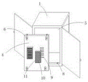
Fig. 1 is a schematic view of an overall structure of a conveniently detachable inlet wire cabinet structure according to the present invention.
Fig. 2 is a schematic view of a partial structure of a wire inlet cabinet structure convenient to disassemble and assemble.
FIG. 3 is a schematic structural view of a clamping assembly in a wire inlet cabinet structure convenient for disassembly and assembly according to the present invention
In the figure: 1. a main body of the incoming cabinet; 2. a first guard gate; 3. a second guard gate; 4. a side plate; 5. mounting grooves; 6. a clamping assembly; 7. a heat dissipating component; 8. a limiting hole; 9. a heat sink; 10. a protective net; 11. a protective frame; 12. a slide hole; 13. a first active cavity; 14. a tension spring; 15. fixing the rod; 16. a second movable chamber; 17. a chute; 18. a movable block; 19. a through hole; 20. a limiting rod.
Detailed Description
In order to make the technical means, the creation characteristics, the achievement purposes and the effects of the utility model easy to understand, the utility model is further described with the specific embodiments.
Detailed description of the preferred embodiment
This embodiment is an inlet wire cabinet structure convenient to dismouting.
As shown in fig. 1-3, including inlet wire cabinet main part 1, the one end surface of inlet wire cabinet main part 1 is provided with first guard gate 2, the other end surface of inlet wire cabinet main part 1 is provided with second guard gate 3, mounting groove 5 has been seted up to the both sides surface of inlet wire cabinet main part 1, the inside of mounting groove 5 is provided with curb plate 4, be provided with joint subassembly 6 between curb plate 4 and the inlet wire cabinet main part 1, curb plate 4 passes through joint subassembly 6 and can dismantle with inlet wire cabinet main part 1 and be connected, the middle part of curb plate 4 is provided with radiator unit 7, spacing hole 8 has been seted up at the four corners of mounting groove 5, and be the joint between curb plate 4 and the mounting groove 5.
The heat dissipation assembly 7 comprises a heat dissipation groove 9, a protective net 10 and a protective frame 11, the heat dissipation groove 9 is formed in the middle of the side plate 4, the protective frame 11 is fixedly installed on the outer surface of one side of the side plate 4, the heat dissipation groove 9 is located inside the protective frame 11, the protective net 10 is fixedly installed on the outer surface of one side of the protective frame 11, a fixing screw is arranged between the protective frame 11 and the side plate 4, and the protective frame 11 is fixedly connected with the side plate 4 through the fixing screw; the clamping assembly 6 comprises a sliding hole 12, a first movable cavity 13, a telescopic spring 14, a fixed rod 15, a second movable cavity 16, a sliding groove 17, a movable block 18, a through hole 19 and a limiting rod 20, wherein the through hole 19 is formed in four corners of the outer wall of the side plate 4, the second movable cavity 16 is formed at one point of the through hole 19, the sliding groove 17 is formed in four corners of the outer surface of one side of the side plate 4, the second movable cavity 16 is communicated with the sliding groove 17 and the through hole 19, and the outer wall of one end of the limiting rod 20 is clamped with the limiting hole 8; the fixed rod 15 is fixedly arranged at the lower part of the second movable cavity 16, the sliding hole 12 is formed in the outer surface of the upper end of the fixed rod 15, the first movable cavity 13 is positioned at the lower part of the sliding hole 12, the telescopic spring 14 is positioned in the first movable cavity 13, the outer surface of the lower end of the telescopic spring 14 is fixedly connected with the lower part of the first movable cavity 13, the outer surface of the upper end of the telescopic spring 14 is fixedly connected with the outer surface of the lower end of the limiting rod 20, and the movable block 18 is fixedly arranged in the middle of the outer surface of one side of the limiting rod 20; the outer wall of the limiting rod 20 is in sliding connection with the through hole 19 and the sliding hole 12, and the outer wall of the movable block 18 is in sliding connection with the sliding groove 17; the lower part of the limiting rod 20 is elastically connected with one end of the first movable cavity 13 through a telescopic spring 14.
The utility model is a wire inlet cabinet structure convenient for disassembly and assembly, in order to facilitate the assembly and the disassembly between a side plate 4 and a wire inlet cabinet main body 1, a clamping component 6 is arranged, when the side plate 4 is assembled, a movable block 18 is firstly pressed down, the movable block 18 slides along a sliding groove 17, the movable block 18 drives a limiting rod 20 to descend, the lower part of the limiting rod 20 extrudes a telescopic spring 14 in a first movable cavity 13, the upper part of the limiting rod 20 enters a through hole 19, then the side plate 4 is clamped in an installation groove 5, the movable block 18 is loosened, and due to the reset effect of the telescopic spring 14, the limiting rod 20 is inserted into a limiting hole 8, the assembly is completed, and the disassembly is convenient; the radiating assembly 7 that sets up, through the radiating groove 9 that opens and shuts at the outer wall of curb plate 4, is convenient for dispel the heat to inlet wire cabinet main part 1 inside, and through the protection network 10 and the protective frame 11 that set up, plays certain guard action.
Detailed description of the utility model
The embodiment is an embodiment of the clamping component 6 in the incoming line cabinet structure convenient to disassemble and assemble.
As shown in fig. 1, 2 and 3, a clamping assembly 6 for a conveniently detachable wire inlet cabinet structure, the clamping assembly 6 comprises a sliding hole 12, a first movable cavity 13, a telescopic spring 14, a fixed rod 15, a second movable cavity 16, a sliding groove 17, a movable block 18, a through hole 19 and a limiting rod 20, the through hole 19 is arranged at four corners of the outer wall of a side plate 4, the second movable cavity 16 is arranged at one point of the through hole 19, the sliding groove 17 is arranged at four corners of the outer surface of one side of the side plate 4, the second movable cavity 16 is communicated with the sliding groove 17 and the through hole 19, and the outer wall of one end of the limiting rod 20 is clamped with a limiting hole 8; the fixed rod 15 is fixedly arranged at the lower part of the second movable cavity 16, the sliding hole 12 is formed in the outer surface of the upper end of the fixed rod 15, the first movable cavity 13 is positioned at the lower part of the sliding hole 12, the telescopic spring 14 is positioned in the first movable cavity 13, the outer surface of the lower end of the telescopic spring 14 is fixedly connected with the lower part of the first movable cavity 13, the outer surface of the upper end of the telescopic spring 14 is fixedly connected with the outer surface of the lower end of the limiting rod 20, and the movable block 18 is fixedly arranged in the middle of the outer surface of one side of the limiting rod 20; the outer wall of the limiting rod 20 is in sliding connection with the through hole 19 and the sliding hole 12, and the outer wall of the movable block 18 is in sliding connection with the sliding groove 17; the lower part of the limiting rod 20 is elastically connected with one end of the first movable cavity 13 through the telescopic spring 14, so that the side plate 4 can be conveniently disassembled and assembled.
It is noted that, herein, relational terms such as first and second (a, b, etc.) and the like may be used solely to distinguish one entity or action from another entity or action without necessarily requiring or implying any actual such relationship or order between such entities or actions. Also, the terms "comprises," "comprising," or any other variation thereof, are intended to cover a non-exclusive inclusion, such that a process, method, article, or apparatus that comprises a list of elements does not include only those elements but may include other elements not expressly listed or inherent to such process, method, article, or apparatus. Without further limitation, an element defined by the phrase "comprising an … …" does not exclude the presence of other identical elements in a process, method, article, or apparatus that comprises the element.
The foregoing shows and describes the general principles and broad features of the present invention and advantages thereof. It will be understood by those skilled in the art that the present invention is not limited to the embodiments described above, which are described in the specification and illustrated only to illustrate the principle of the present invention, but that various changes and modifications may be made therein without departing from the spirit and scope of the present invention, which fall within the scope of the utility model as claimed.
Claims (6)
1. The utility model provides an inlet wire cabinet structure convenient to dismouting, includes inlet wire cabinet main part (1), its characterized in that: the utility model discloses a cabinet of entereing a telephone line, including inlet wire cabinet main part (1), the one end surface of inlet wire cabinet main part (1) is provided with first guard gate (2), the other end surface of inlet wire cabinet main part (1) is provided with second guard gate (3), mounting groove (5) have been seted up to the both sides surface of inlet wire cabinet main part (1), the inside of mounting groove (5) is provided with curb plate (4), be provided with joint subassembly (6) between curb plate (4) and inlet wire cabinet main part (1), curb plate (4) can be dismantled with inlet wire cabinet main part (1) through joint subassembly (6) and be connected, the middle part of curb plate (4) is provided with radiator unit (7), spacing hole (8) have been seted up in the four corners of mounting groove (5), just be the joint between curb plate (4) and mounting groove (5).
2. The incoming line cabinet structure convenient to disassemble and assemble according to claim 1, characterized in that: radiating component (7) include radiating groove (9), protection network (10) and protective frame (11), just radiating groove (9) are seted up in the middle part of curb plate (4), protective frame (11) fixed mounting goes in one side surface of curb plate (4), just radiating groove (9) are located the inside of protective frame (11), protection network (10) fixed mounting is in one side surface of protective frame (11), be provided with the fixed screw between protective frame (11) and curb plate (4), protective frame (11) are through fixed screw and curb plate (4) fixed connection.
3. The incoming line cabinet structure convenient to disassemble and assemble according to claim 1, characterized in that: joint subassembly (6) are including slide opening (12), first activity chamber (13), expanding spring (14), dead lever (15), second activity chamber (16), spout (17), movable block (18), through-hole (19) and gag lever post (20), just four corners of curb plate (4) outer wall is seted up in through-hole (19), the second activity chamber (16) is seted up in one point of through-hole (19), the four corners of curb plate (4) one side surface is seted up in spout (17), just second activity chamber (16) communicates with each other with spout (17), through-hole (19), just be the joint between outer wall and spacing hole (8) of gag lever post (20) one end.
4. The incoming line cabinet structure convenient to disassemble and assemble according to claim 3, characterized in that: dead lever (15) fixed mounting is in the lower part in second activity chamber (16), the upper end surface of dead lever (15) is seted up in slide opening (12), first activity chamber (13) are located the lower part of slide opening (12), expanding spring (14) are located first activity chamber (13), just the lower extreme surface of expanding spring (14) and the lower part fixed connection in first activity chamber (13), the upper end surface of expanding spring (14) is connected with the lower extreme surface fixed connection of gag lever post (20), movable block (18) fixed mounting is in the middle part of gag lever post (20) one side surface.
5. The incoming line cabinet structure convenient to disassemble and assemble according to claim 3, characterized in that: the outer wall of the limiting rod (20) is in sliding connection with the through hole (19) and the sliding hole (12), and the outer wall of the movable block (18) is in sliding connection with the sliding groove (17).
6. The incoming line cabinet structure convenient to disassemble and assemble according to claim 3, characterized in that: the lower part of the limiting rod (20) is elastically connected with one end of the first movable cavity (13) through a telescopic spring (14).
Priority Applications (1)
| Application Number | Priority Date | Filing Date | Title |
|---|---|---|---|
| CN202220135299.1U CN216929264U (en) | 2022-01-19 | 2022-01-19 | Incoming line cabinet structure convenient to dismouting |
Applications Claiming Priority (1)
| Application Number | Priority Date | Filing Date | Title |
|---|---|---|---|
| CN202220135299.1U CN216929264U (en) | 2022-01-19 | 2022-01-19 | Incoming line cabinet structure convenient to dismouting |
Publications (1)
| Publication Number | Publication Date |
|---|---|
| CN216929264U true CN216929264U (en) | 2022-07-08 |
Family
ID=82262220
Family Applications (1)
| Application Number | Title | Priority Date | Filing Date |
|---|---|---|---|
| CN202220135299.1U Active CN216929264U (en) | 2022-01-19 | 2022-01-19 | Incoming line cabinet structure convenient to dismouting |
Country Status (1)
| Country | Link |
|---|---|
| CN (1) | CN216929264U (en) |
-
2022
- 2022-01-19 CN CN202220135299.1U patent/CN216929264U/en active Active
Similar Documents
| Publication | Publication Date | Title |
|---|---|---|
| CN211531521U (en) | Electromechanical device protector | |
| CN222169336U (en) | A photovoltaic grid-connected cabinet that is easy to assemble | |
| CN219760449U (en) | System integrated control cabinet convenient to install component | |
| CN219761678U (en) | Rack heat abstractor convenient to maintain | |
| CN221947696U (en) | A power distribution cabinet with temperature adjustment function | |
| CN216598542U (en) | Distribution network electrical cabinet | |
| CN219371769U (en) | An assembled low-voltage power cabinet | |
| CN219247264U (en) | Mounting structure of block terminal | |
| CN220492495U (en) | Distribution box support used in distribution box | |
| CN219477368U (en) | Cable trench distribution box | |
| CN220586541U (en) | Display backboard component heat dissipation structure and backboard component | |
| CN212908623U (en) | Weak current switch board | |
| CN222073745U (en) | A server cabinet | |
| CN217470662U (en) | High-efficient radiating aluminium system electronic radiator | |
| CN213304731U (en) | Block terminal for electrical engineering | |
| CN222814111U (en) | Assembled sheet type HXGN-12 high-voltage cabinet convenient to assemble | |
| CN220710961U (en) | Air cooling structure of control cabinet | |
| CN221057919U (en) | Switch board protective structure | |
| CN222089084U (en) | Module combined type outdoor power distribution cabinet | |
| CN219892000U (en) | Lead type power transformer | |
| CN222851894U (en) | Protective component of medium-voltage ring main unit | |
| CN214957892U (en) | Portable dampproofing cubical switchboard of inner panel convenient to change | |
| CN220797513U (en) | Low-voltage power distribution cabinet body | |
| CN211456026U (en) | Smart jack convenient to heat dissipation | |
| CN220042802U (en) | Ring main unit with operation and maintenance interface |
Legal Events
| Date | Code | Title | Description |
|---|---|---|---|
| GR01 | Patent grant | ||
| GR01 | Patent grant |