CN211492377U - Plastic granulation production line - Google Patents
Plastic granulation production line Download PDFInfo
- Publication number
- CN211492377U CN211492377U CN201921973895.1U CN201921973895U CN211492377U CN 211492377 U CN211492377 U CN 211492377U CN 201921973895 U CN201921973895 U CN 201921973895U CN 211492377 U CN211492377 U CN 211492377U
- Authority
- CN
- China
- Prior art keywords
- roller
- plastic
- air
- rotating roller
- extruder
- Prior art date
- Legal status (The legal status is an assumption and is not a legal conclusion. Google has not performed a legal analysis and makes no representation as to the accuracy of the status listed.)
- Active
Links
Images


Landscapes
- Processing And Handling Of Plastics And Other Materials For Molding In General (AREA)
Abstract
The utility model belongs to the technical field of plastic granulation, and discloses a plastic granulation production line, which comprises a stirring tank, an extruder, a cooling water tank, a guide mechanism, a first air drying mechanism, a second air drying mechanism and a plastic granulation mechanism which are arranged in sequence; an inclined guide pipe is arranged at a discharge port of the stirring tank, and a discharge end of the inclined guide pipe is positioned above a feed hopper of the extruder; the plastic strips extruded from the discharge end of the extruder sequentially pass through circulating cold water of a cooling water tank, a guide mechanism, a first air drying mechanism, a second air drying mechanism and a plastic granulating mechanism; an air cooling mechanism is arranged between the discharge end of the extruder and the cooling water tank, the air cooling mechanism comprises an air cooling motor and a fan, and the air cooling motor is in transmission connection with a rotating shaft of the fan. The plastic strip is dried through first air-dry mechanism and second air-dry mechanism, is cut the granulation by plastics granulation mechanism again, can not influence the effect of cutting process because of carrying the water of cooling trough on the plastic strip.
Description
Technical Field
The utility model belongs to the technical field of the plastics granulation, concretely relates to plastics granulation production line.
Background
The traditional plastic granulation process comprises the following steps: the molten polymer is extruded from a die, cooled by a horizontally arranged cooling water tank into plastic strips, cut into granules by a rotating knife, taken out of a granulating chamber by a temperature-regulated water and fed into a centrifugal drier, and the granules are subjected to moisture removal by the centrifugal drier. In the process, the plastic strips directly enter the cutting process from the cooling water tank, and the plastic strips can carry water in the cooling water tank to influence the effect of the cutting process.
In order to solve the technical problem, a plastic granulating production line is provided.
SUMMERY OF THE UTILITY MODEL
In order to solve the problems existing in the prior art, the utility model aims to provide a plastic granulation production line.
The utility model discloses the technical scheme who adopts does:
a plastic granulation production line comprises a stirring tank, an extruder, a cooling water tank, a guide mechanism, a first air drying mechanism, a second air drying mechanism and a plastic granulation mechanism which are arranged in sequence;
an inclined guide pipe is arranged at a discharge port of the stirring tank, and a discharge end of the inclined guide pipe is opposite to a feed hopper of the extruder;
the plastic strips extruded from the discharge end of the extruder sequentially pass through the circulating cold water of the cooling water tank, the guide mechanism, the first air drying mechanism, the second air drying mechanism and the plastic granulating mechanism;
the extruder is characterized in that an air cooling mechanism is arranged between the discharge end of the extruder and the cooling water tank, the air cooling mechanism comprises an air cooling motor and a fan, the air cooling motor is installed on one side of the extruder, and the air cooling motor is in transmission connection with a rotating shaft of the fan.
Further, the first air drying mechanism comprises an air blower, a cover body with an opening at the lower end, a drying box with an opening at the upper end, a first rotating roller and a second rotating roller;
a first through groove and a second through groove for plastic strips to pass through are respectively formed in the left side of the upper end and the right side of the upper end of the drying box;
the blower is connected with the cover body through an air pipe, and the cover body covers the drying box;
the first rotating roller and the second rotating roller are arranged in the drying box in a left-right mode, and are both rotatably arranged in the drying box;
the first rotating roller and the second rotating roller are identical in structure, annular grooves are formed in the first rotating roller in an annular mode at equal intervals, and plastic strips coming out of the guide mechanism sequentially penetrate through the first through groove, the annular groove in the first rotating roller, the annular groove in the second rotating roller and the second through groove.
Further, the plastic strip is tangent to the first rotating roller and the second rotating roller respectively.
Further, the second air drying mechanism also comprises an air blower, a cover body with an opening at the lower end, a drying box with an opening at the upper end, a first rotating roller and a second rotating roller;
the second air drying mechanism further comprises a roller motor and a roller set, the roller motor is in transmission connection with a central shaft of the roller set, and the roller set is arranged between a first roller and a second roller of the second air drying mechanism;
the roller group comprises an outer shell, a central shaft, a third roller and a fourth roller, the third roller and the fourth roller are symmetrically distributed on two sides of the central shaft, and the central shaft is coaxially arranged on the outer shell;
the third rotating roller and the fourth rotating roller are both the same as the first rotating roller in structure;
the plastic strip is tangent to the third rotating roller or the fourth rotating roller.
Further, the guide mechanism comprises a first guide roller and a second guide roller which can rotate, and the first guide roller and the second guide roller are the same as the first rotating roller in structure;
and the plastic strips passing through the cooling water tank sequentially pass through the lower end of the first guide roller and the upper end of the second guide roller.
Furthermore, the upper surface of the cover body is a hemispherical surface.
The utility model has the advantages that:
the pivoted fan can carry out the forced air cooling heat dissipation for the plastic strip that extrudes, make the plastic strip carry out the forced air cooling heat dissipation design earlier, then carry out the water-cooling heat dissipation design through the circulation cold water of cooling trough, can make the holistic temperature of plastic strip or organize and reach the requirement, can effectively avoid the plastic strip stress defect to appear, and the quality of plastic strip is higher, in addition, the plastic strip is through first air-dry mechanism and second air-dry mechanism drying back, cut the granulation by plastics granulation mechanism again, can not influence the effect of cutting process because of the water that carries the cooling trough on the plastic strip.
Drawings
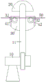
FIG. 1 is a schematic view of a first seasoning mechanism.
Fig. 2 is a schematic structural view of the first rotating roller of the present invention.
Fig. 3 is a schematic structural view of the second seasoning mechanism.
Fig. 4 is a schematic structural view of the roll stack of the present invention.
Fig. 5 is a side view of the first through slot.
Fig. 6 is a schematic structural view of the plastic granulation production line of the present invention.
Fig. 7 is a schematic view of the structure of the air-cooled motor and fan.
In the figure: 10-a blower; 11-air pipe; 20-a cover body; 30-drying the box; 31-a first through slot; 32-a second through slot; 41-a first rotating roller; 401-an annular groove; 402-a rotating shaft; 42-a second rotating roller; 43-a third roller; 44-a fourth rotating roller; 45-central axis; 46-an outer shell; 47-a roller motor; 50-plastic strips; 61-a stirring tank; 62-inclined guide tube; 70-an extruder; 71-a feed hopper; 72-discharge end of extruder; 81-a fan; 811-the axis of rotation of the fan; 82-a cooling water tank; 83-a first guide roll; 84-a second guide roll; 85-air cooling motor; 90-a plastic granulation mechanism; .
Detailed Description
The present invention will be further described with reference to the accompanying drawings and specific embodiments.
As shown in fig. 6, the plastic granulation production line of the present embodiment includes a stirring tank 61, an extruder 70, a cooling water tank 82, a guiding mechanism, a first air-drying mechanism, a second air-drying mechanism, and a plastic granulation mechanism 90, which are sequentially arranged; the method comprises the steps of putting mixed materials (the mixed materials comprise plastics, auxiliaries and the like) into a stirring tank 61, stirring and uniformly mixing, putting the uniformly mixed materials into an extruder for extrusion molding (the model of the extruder is xx), cooling and shaping plastic strips extruded by the extruder by circulating cold water in a cooling water tank, drying the plastic strips by a first air drying mechanism and a second air drying mechanism after cooling and shaping, and finally cutting the plastic strips into granules by a plastic granulating mechanism.
An inclined guide pipe 62 is arranged at a discharge port of the stirring tank 61, and a discharge end of the inclined guide pipe is opposite to a feed hopper 71 of the extruder; the mixed material uniformly mixed by the stirring tank enters a feed hopper 71 of the extruder through the inclined guide pipe 62, and then is extruded and molded by the extruder.
The plastic strips extruded from the discharge end of the extruder sequentially pass through the circulating cold water of the cooling water tank 82, the guide mechanism, the first air drying mechanism, the second air drying mechanism and the plastic granulating mechanism; the plastic strip can be transported in the left-right direction (see fig. 6). Discharge end 72 of extruder with be equipped with air cooling mechanism between cooling trough 82, air cooling mechanism includes air-cooled motor 85 and fan 81, the air-cooled motor is installed one side of extruder, the transmission of air-cooled motor is connected pivot 811 (as shown in fig. 7) of fan, the air-cooled motor can drive the fan and rotate, and the fan setting can carry out the forced air cooling heat dissipation for extruded plastic strip 50 in the front side top of the discharge end 72 of extruder, and the pivoted fan makes the plastic strip advance to carry out the forced air cooling heat dissipation design, then carries out the water-cooling heat dissipation design through the circulation cold water by cooling trough 82, can make the holistic temperature of plastic strip or tissue reach the requirement, can effectively avoid the plastic strip stress defect to appear, and the quality of plastic strip is higher.
Before the plastic strips are cut into granules by the plastic granulating mechanism, the plastic strips can be dried by the first air drying mechanism and the second air drying mechanism, and the effect of the granulating process cannot be influenced by water carrying the cooling water tank on the plastic strips.
As shown in fig. 1, the first seasoning mechanism includes a blower 10, a cover 20 having an open lower end, a drying box 30 having an open upper end, a first rotary roller 41, and a second rotary roller 42. After the plastic strips 50 come out of the cooling water tank, the plastic strips are air-dried through the first air-drying mechanism and the second air-drying mechanism, and the effect of the granulating process cannot be influenced by water carrying the cooling water tank on the plastic strips.
The left side of the upper end and the right side of the upper end of the drying box are respectively provided with a first through groove 31 (a side view of the first through groove 31 is shown in fig. 5) and a second through groove 32 for the plastic strip 50 to pass through; after the plastic strips come out from the cooling water tank, the plastic strips enter the drying box of the first air drying mechanism through the first through groove 31, and after the air drying operation, the plastic strips leave the drying box of the first air drying mechanism through the second through groove 32.
The blower 10 is connected with the cover body 20 through an air pipe 11, and the cover body is covered above the drying box; the cover body is arranged as shown in fig. 1, and air blown by the blower is supplied to the cover body through the air pipe, so that the plastic strips below the cover body can be dried.
The first rotating roller 41 and the second rotating roller 42 are arranged in the drying box 30 left and right, and are rotatably arranged in the drying box; the two ends of the rotating shaft 402 of the first rotating roller and the second rotating roller are both installed on the drying box through rotating bearings, so that the first rotating roller and the second rotating roller can be stably installed and freely rotate. The plastic strip 50 is guided by the first rotating roller 41 and the second rotating roller 42, and can be displaced in the left-right direction better. Because the first rotating roller and the second rotating roller can rotate, the plastic strip which moves along the left and right directions cannot be influenced by overlarge reverse friction force.
The first rotating roller and the second rotating roller have the same structure, as shown in fig. 2, annular grooves 401 are annularly arranged on the first rotating roller 41 at equal intervals, as shown in fig. 1, and plastic strips 50 coming out of the guide mechanism sequentially penetrate through the first through groove 31, the annular groove 401 on the first rotating roller, the annular groove 401 on the second rotating roller and the second through groove 32. After the plastic strips come out of the cooling water tank, the plastic strips enter a drying box of the first air drying mechanism through the first through groove; then guided by a first rotating roller and a second rotating roller, preferably the plastic strips are respectively tangent to the first rotating roller and the second rotating roller, so that the plastic strips which are displaced along the left-right direction can be better guided by the first rotating roller 41 and the second rotating roller 42; the plastic strips 50 guided along the first and second rotating rollers are dried by the wind in the upper cover 20, and finally the plastic strips 50 leave the drying box 30 through the second through grooves 32; therefore, the plastic strips enter the cutting process after being dried by the first air drying mechanism, and the effect of the cutting process cannot be influenced by water carrying the cooling water tank on the plastic strips.
The upper surface of the cover body 20 is a hemispherical surface, so that air blown by the blower can be better blown downwards to air-dry the lower plastic strips.
A guide mechanism is arranged between the cooling water tank and the first air drying mechanism and comprises a rotatable first guide roller 83 and a rotatable second guide roller 84, and the first guide roller and the second guide roller are both identical to the first rotary roller in structure; the rotating shafts of the first guide roller and the second guide roller are both mounted on the mounting plate of the first guide roller through rotating bearings, and the plastic strips passing through the cooling water tank sequentially pass through the lower end of the first guide roller and the upper end of the second guide roller (the first guide roller 83 and the second guide roller 84 can rotate, and cannot affect the forward transmission of the plastic strips along the left-right direction), so that the plastic strips coming out of the cooling water tank are guided by the first guide roller and the second guide roller and enter the first air drying mechanism from the cooling water tank according to the diagram.
As shown in fig. 3, the second air drying mechanism also includes a blower, a cover body with an opening at the lower end, a drying box with an opening at the upper end, a first rotating roller and a second rotating roller; the connection relation and the working principle of the blower of the second air drying mechanism, the cover body with an opening at the lower end, the drying box with an opening at the upper end, the first rotating roller and the second rotating roller are the same as those of the first air drying mechanism, and the description is omitted here.
The second air drying mechanism further comprises a roller motor 47 and a roller group, the roller motor 47 is in transmission connection with a central shaft of the roller group, and the roller group is arranged between a first roller and a second roller of the second air drying mechanism; after the roller motor 47 operates, the roller group is driven to rotate, and the rotating force and the rotating wind power formed by the rotating roller group can take away the moisture on the plastic strips, so that the plastic strips can be better dried.
The roller group comprises an outer shell 46, a central shaft 45, a third roller 43 and a fourth roller 44, wherein the third roller 43 and the fourth roller 44 are symmetrically distributed on two sides of the central shaft, and the central shaft is coaxially arranged on the outer shell; as shown in fig. 4, the third rotating roller and the fourth rotating roller have the same structure as the first rotating roller; the number of shell bodies is two, and two shell bodies are installed respectively at the both ends of center pin, and the both ends that roller 43 and fourth changeed roller 44 are all installed on the shell body of same end to the third. The one end transmission of center pin is connected and is changeed the roller motor, changes the roller motor during operation, can drive the center pin and rotate to drive shell body, third commentaries on classics roller and fourth commentaries on classics roller and rotate, the third is changeed the roller and is kept away from the plastic strip (during the original, the plastic strip tangent in the third changes the roller), and the fourth changes the roller and slowly rotates and tangent with the plastic strip, and this in-process, the third changes the rotatory revolving force that forms of roller and rotatory wind-force and can take away the moisture on the plastic strip, and then the rotatory revolving force that forms of fourth commentaries on classics roller and rotatory wind-force can take away the moisture on the plastic strip in turn, and the third changes roller and fourth and changes the roller and take away the moisture on the plastic strip in turn, can.
The plastic strip 50 sequentially passes through the first through groove 31 of the second air drying mechanism, the annular groove 401 on the first rotating roller, the rotating roller group, the annular groove 401 on the second rotating roller and the second through groove 32. After the plastic strips come out of the cooling water tank, the plastic strips enter a drying box of the second air drying mechanism through a first through groove of the second air drying mechanism; then the plastic strips 50 guided along the first rotating roller and the second rotating roller of the second air-drying mechanism are air-dried by the air in the cover body 20 of the second air-drying mechanism, in addition, the third rotating roller and the fourth rotating roller can alternately take away the moisture on the plastic strips, so that the plastic strips displaced along the left and right directions can be better air-dried, and finally the plastic strips 50 pass through the second through groove 32 of the second air-drying mechanism and leave the drying box 30 of the second air-drying mechanism; therefore, the plastic strips are dried by the second air drying mechanism and then cut and granulated by the plastic granulating mechanism 90, and the effect of the cutting process cannot be influenced by the water carried by the plastic strips and used as the cooling water tank.
The present invention is not limited to the above-mentioned optional embodiments, and any other products in various forms can be obtained by anyone under the teaching of the present invention, and any changes in the shape or structure thereof, all the technical solutions falling within the scope of the present invention, are within the protection scope of the present invention.
Claims (6)
1. A plastic granulation production line is characterized in that: the plastic granulating device comprises a stirring tank, an extruder, a cooling water tank, a guide mechanism, a first air drying mechanism, a second air drying mechanism and a plastic granulating mechanism which are arranged in sequence;
an inclined guide pipe is arranged at a discharge port of the stirring tank, and a discharge end of the inclined guide pipe is positioned above a feed hopper of the extruder;
the plastic strips extruded from the discharge end of the extruder sequentially pass through the circulating cold water of the cooling water tank, the guide mechanism, the first air drying mechanism, the second air drying mechanism and the plastic granulating mechanism;
the extruder is characterized in that an air cooling mechanism is arranged between the discharge end of the extruder and the cooling water tank, the air cooling mechanism comprises an air cooling motor and a fan, the air cooling motor is installed on one side of the extruder, and the air cooling motor is in transmission connection with a rotating shaft of the fan.
2. The plastic pelletizing line of claim 1, characterized in that: the first air drying mechanism comprises an air blower, a cover body with an opening at the lower end, a drying box with an opening at the upper end, a first rotating roller and a second rotating roller;
the blower is connected with the cover body through an air pipe, and the cover body covers the drying box;
a first through groove and a second through groove for plastic strips to pass through are respectively formed in the left side of the upper end and the right side of the upper end of the drying box;
the first rotating roller and the second rotating roller are arranged in the drying box in a left-right mode, and are both rotatably arranged in the drying box;
the first rotating roller and the second rotating roller are identical in structure, annular grooves are formed in the first rotating roller in an annular mode at equal intervals, and plastic strips coming out of the guide mechanism sequentially penetrate through the first through groove, the annular groove in the first rotating roller, the annular groove in the second rotating roller and the second through groove.
3. A plastic pelletizing line as set forth in claim 2, characterized in that: the plastic strip is tangent to the first rotating roller and the second rotating roller respectively.
4. A plastic pelletizing line as set forth in claim 3, characterized in that: the second air drying mechanism also comprises an air blower, a cover body with an opening at the lower end, a drying box with an opening at the upper end, a first rotating roller and a second rotating roller;
the second air drying mechanism further comprises a roller motor and a roller set, the roller motor is in transmission connection with a central shaft of the roller set, and the roller set is arranged between a first roller and a second roller of the second air drying mechanism;
the roller group comprises an outer shell, a central shaft, a third roller and a fourth roller, the third roller and the fourth roller are symmetrically distributed on two sides of the central shaft, and the central shaft is coaxially arranged on the outer shell;
the third rotating roller and the fourth rotating roller are both the same as the first rotating roller in structure;
the plastic strip is tangent to the third rotating roller or the fourth rotating roller.
5. A plastic pelletizing line according to any one of claims 2 to 4, characterized in that: the guide mechanism comprises a first guide roller and a second guide roller which can rotate, and the first guide roller and the second guide roller are both identical to the first rotating roller in structure;
and the plastic strips passing through the cooling water tank sequentially pass through the lower end of the first guide roller and the upper end of the second guide roller.
6. A plastic pelletizing line as set forth in claim 5, characterized in that: the upper surface of the cover body is a hemispherical surface.
Priority Applications (1)
| Application Number | Priority Date | Filing Date | Title |
|---|---|---|---|
| CN201921973895.1U CN211492377U (en) | 2019-11-14 | 2019-11-14 | Plastic granulation production line |
Applications Claiming Priority (1)
| Application Number | Priority Date | Filing Date | Title |
|---|---|---|---|
| CN201921973895.1U CN211492377U (en) | 2019-11-14 | 2019-11-14 | Plastic granulation production line |
Publications (1)
| Publication Number | Publication Date |
|---|---|
| CN211492377U true CN211492377U (en) | 2020-09-15 |
Family
ID=72409653
Family Applications (1)
| Application Number | Title | Priority Date | Filing Date |
|---|---|---|---|
| CN201921973895.1U Active CN211492377U (en) | 2019-11-14 | 2019-11-14 | Plastic granulation production line |
Country Status (1)
| Country | Link |
|---|---|
| CN (1) | CN211492377U (en) |
Cited By (1)
| Publication number | Priority date | Publication date | Assignee | Title |
|---|---|---|---|---|
| CN113183348A (en) * | 2021-03-03 | 2021-07-30 | 广西梧州国龙再生资源发展有限公司 | Waste plastic recycling and granulating process |
-
2019
- 2019-11-14 CN CN201921973895.1U patent/CN211492377U/en active Active
Cited By (1)
| Publication number | Priority date | Publication date | Assignee | Title |
|---|---|---|---|---|
| CN113183348A (en) * | 2021-03-03 | 2021-07-30 | 广西梧州国龙再生资源发展有限公司 | Waste plastic recycling and granulating process |
Similar Documents
| Publication | Publication Date | Title |
|---|---|---|
| CN203438420U (en) | Granulator | |
| CN206812271U (en) | Extrude pelleter | |
| CN213704113U (en) | High-efficient fire-retardant masterbatch extruder | |
| CN207754516U (en) | A kind of quenched granulation integrated apparatus for producing feed | |
| CN211492377U (en) | Plastic granulation production line | |
| CN201841624U (en) | Forming equipment of wood-plastic composite foaming material | |
| CN210679259U (en) | Extrusion granulation equipment for producing color master batches | |
| CN213699768U (en) | Bio-organic fertilizer prilling granulator | |
| CN115503147B (en) | PVC plastic granules granulation equipment | |
| CN216935918U (en) | Novel dry-method slitting granulator | |
| CN207897871U (en) | A kind of feed extruder | |
| CN208032741U (en) | It is a kind of to crush neat twin-roll tabletting cooling conveying crushing machine | |
| CN215550060U (en) | A prilling granulator for production of degradable plastics | |
| CN210952210U (en) | Drying device for plastic granulation | |
| CN211279311U (en) | Plastic granulating device | |
| CN209882967U (en) | A granular feed cutting machine for feed processing | |
| CN211725684U (en) | Granulator is used in calcium stearate production | |
| CN112847899A (en) | Grain cutting device for plastic molding material | |
| CN205438951U (en) | Take drying device's PLA plastic film granulation system in advance | |
| CN214187936U (en) | Cold drawing strip pelleter | |
| CN214187934U (en) | Cold-drawn strip granulator capable of improving particle quality | |
| CN220113746U (en) | Granule extrusion moulding cutting equipment | |
| CN213107616U (en) | High-efficient pelleter | |
| CN219883223U (en) | PET plastic sheet production facility | |
| CN117047932B (en) | Double-screw extrusion granulator |
Legal Events
| Date | Code | Title | Description |
|---|---|---|---|
| GR01 | Patent grant | ||
| GR01 | Patent grant |