CN211489761U - Automobile chassis machining device - Google Patents
Automobile chassis machining device Download PDFInfo
- Publication number
- CN211489761U CN211489761U CN202020050746.4U CN202020050746U CN211489761U CN 211489761 U CN211489761 U CN 211489761U CN 202020050746 U CN202020050746 U CN 202020050746U CN 211489761 U CN211489761 U CN 211489761U
- Authority
- CN
- China
- Prior art keywords
- chassis
- plate
- sliding
- fixedly connected
- component
- Prior art date
- Legal status (The legal status is an assumption and is not a legal conclusion. Google has not performed a legal analysis and makes no representation as to the accuracy of the status listed.)
- Active
Links
Images


Abstract
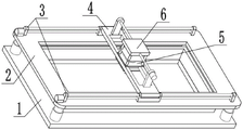
The utility model relates to the technical field of processing, in particular to a processing device for an automobile chassis, which comprises a chassis placing chassis, an extrusion fixing component, a left-right sliding slideway component, a connecting sliding plate component, a chassis perforating device and a perforating lifting device, wherein the automobile chassis is placed on a placing frame, four telescopic rods I are started, the chassis is fixed between the placing frame and an extruding plate, two motors I are started according to the coordinate position of a hole, the connecting slide plate is driven to move by the driving lead screw I, so that the drill bit is positioned at the correct horizontal coordinate position, at starter motor II, drive the lifter plate through the roof and remove to let the drill bit be in the position of correct ordinate, starter motor III and telescopic link II, motor III drives the drill bit and rotates, and telescopic link II drives the drill bit through the lifter plate and moves down, thereby carries out accurate spot facing work to the chassis.
Description
Technical Field
The utility model relates to a processing technology field, more specifically the vehicle chassis processingequipment that says so.
Background
The vehicle is a vehicle that has its own power to drive and can be driven by motor without the need of rail or electric power installation. The automobile is composed of an engine, a chassis, a body, electric equipment and the like, and the automobile chassis is composed of four parts, namely a transmission system, a running system, a steering system and a braking system. The chassis is used for supporting and mounting the automobile engine and all parts and assemblies thereof to form the integral shape of the automobile, and receives the power of the engine to enable the automobile to move and ensure the normal running. Therefore, the automobile chassis is an indispensable part of the automobile, and therefore, it is particularly important to design a device capable of machining holes in the automobile chassis.
Disclosure of Invention
The utility model relates to a processing technology field, more specifically the vehicle chassis processingequipment that says so, place chassis, extrusion fixed component, horizontal slip slide component, connection slide component, chassis perforating device and the elevating gear that punches including the chassis, use this device to carry out accurate spot facing work to vehicle chassis.
The utility model provides an automobile chassis processingequipment, places the chassis including the chassis, this automobile chassis processingequipment still includes extrusion fixed component, horizontal slip slide component, connects slide component, chassis perforating device and the elevating gear that punches, the chassis place fixedly connected with extrusion fixed component on the chassis, two horizontal slip slide components of fixedly connected with on the extrusion fixed component, connect slide component and two horizontal slip slide component sliding connection, sliding connection has chassis perforating device on the connection slide component, perforating elevating gear fixed connection on chassis perforating device and with be connected the slide component and pass through threaded connection.
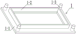
As this technical scheme's further optimization, the utility model relates to an automobile chassis processingequipment the chassis place the chassis including the supporting baseplate, place frame and telescopic link I, fixedly connected with places the frame on the supporting baseplate, the equal fixedly connected with telescopic link I is gone out in the four corners of supporting baseplate upper surface.
As the further optimization of this technical scheme, the utility model relates to an automobile chassis processingequipment the fixed component of extrusion include stripper plate, processing mouth and motor I, stripper plate fixed connection is provided with the processing mouth in four telescopic link I's top on the stripper plate, the equal fixedly connected with motor I in both ends around the stripper plate left end.
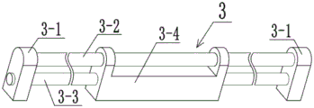
As this technical scheme's further optimization, the utility model relates to an automobile chassis processingequipment the horizontal slip slide component include fixed block, spacing traveller, drive screw I and linkage frame, the fixed block be provided with two, the spacing traveller of fixedly connected with between two fixed blocks, drive screw I's both ends are rotated with two fixed blocks and are connected, linkage frame and spacing traveller sliding connection pass through threaded connection with drive screw I, the equal fixed connection of two sets of fixed blocks is on the stripper plate, two motor I's output shaft respectively with two drive screw I fixed connection.
As this technical scheme's further optimization, the utility model relates to an automobile chassis processingequipment the connection slide component including connecting slide, sliding opening, bearing frame, drive screw II and motor II, the both ends of connecting the slide respectively with two spacing traveller sliding connection, the both ends of connecting the slide are located two linkage frames, be provided with the sliding opening on connecting the slide, connect two bearing frames of fixedly connected with on the slide, drive screw II's both ends rotate with two bearing frames respectively and are connected, motor II fixed connection on the bearing frame that is located the rear end and with drive screw II fixed connection.
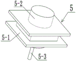
As a further optimization of this technical scheme, the utility model relates to an automobile chassis processingequipment chassis perforating device include slider board, motor III and drill bit, slider board sliding connection is in the spout, and slider inboard sliding connection has motor III, fixedly connected with drill bit on motor III's the output shaft.
As this technical scheme's further optimization, the utility model relates to an automobile chassis processingequipment punching elevating gear include roof, upstand, telescopic link II and lifter plate, the roof passes through threaded connection with drive screw II, four upstands of fixedly connected with and a telescopic link II respectively on four angles of roof lower extreme and the central point put, lifter plate and four upstand sliding connection and with telescopic link II's below fixed connection, motor III and lifter plate fixed connection.
The utility model relates to an automobile chassis processingequipment's beneficial effect does:
place automobile chassis place on the frame and start four telescopic link I, fix the chassis and place between frame and the stripper plate, at this moment according to the coordinate position in hole, start two motor I, it removes to drive the connection slide through drive screw I, let the drill bit be in the position of correct abscissa, at starter motor II, drive the lifter plate through the roof and remove, thereby let the drill bit be in the position of correct ordinate, starter motor III and telescopic link II, motor III drives the drill bit and rotates, telescopic link II moves the drill bit through the lifter plate and removes downwards, thereby carry out accurate spot facing work to the chassis.
Drawings
The present invention will be described in further detail with reference to the accompanying drawings and specific embodiments.
FIG. 1 is a schematic structural view of an automobile chassis processing device of the present invention;
FIG. 2 is a schematic view of a chassis placement chassis structure;
FIG. 3 is a schematic view of the extrusion fastening member;
FIG. 4 is a schematic structural view of a left and right glide slope component;
FIG. 5 is a schematic view of the structure of the connecting slide member;
FIG. 6 is a schematic structural view of a chassis perforating device;
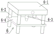
fig. 7 is a schematic structural view of the punching lifting device.
In the figure: a chassis placing chassis 1; a support base plate 1-1; placing a frame 1-2; a telescopic rod I1-3; the pressing and fixing member 2; 2-1 of an extrusion plate; processing a port 2-2; motor I2-3; a left-right sliding track member 3; 3-1 of a fixed block; 3-2 of a limiting sliding column; the transmission lead screw I3-3; 3-4 of a linkage frame; a connecting slide member 4; connecting the sliding plate 4-1; 4-2 of a sliding opening; 4-3 of a bearing seat; a transmission lead screw II 4-4; motor II 4-5; a chassis perforating device 5; a slider plate 5-1; motor III 5-2; 5-3 of a drill bit; a punching lifting device 6; a top plate 6-1; 6-2 of vertical column; the telescopic rod II 6-3; and 6-4 of a lifting plate.
Detailed Description
The first embodiment is as follows:
the following description of the embodiment is made with reference to fig. 1-7, and the present invention relates to the processing technology field, and more specifically to a processing device for an automobile chassis, which comprises a chassis placing chassis 1, an extrusion fixing member 2, a left-right sliding slideway member 3, a connecting sliding plate member 4, a chassis punching device 5 and a punching lifting device 6, wherein the chassis placing chassis is placed on a placing frame 1-2, four telescopic rods I1-3 are started, the chassis is fixed between the placing frame 1-2 and a pressing plate 2-1, two motors I2-3 are started according to the coordinate position of a hole, the connecting sliding plate 4-1 is driven to move through a driving screw I3-3, a drill 5-3 is positioned at the correct horizontal coordinate position, the lifting plate 6-4 is driven to move through a top plate 6-1 when the motor II4-5 is started, so that the drill bit 5-3 is positioned at the correct vertical coordinate position, the motor III5-2 and the telescopic rod II6-3 are started, the motor III5-2 drives the drill bit 5-3 to rotate, and the telescopic rod II6-3 drives the drill bit 5-3 to move downwards through the lifting plate 6-4, so that the chassis is accurately processed;
the utility model provides an automobile chassis processingequipment, places chassis 1 including the chassis, this automobile chassis processingequipment still includes extrusion fixed component 2, horizontal slip slide component 3, connects slide component 4, chassis perforating device 5 and the elevating gear 6 that punches, the chassis place fixedly connected with extrusion fixed component 2 on the chassis 1, two horizontal slip slide components 3 of fixedly connected with on the extrusion fixed component 2, connect slide component 4 and two horizontal slip slide components 3 sliding connection, sliding connection has chassis perforating device 5 on connecting slide component 4, perforating elevating gear 6 fixed connection on chassis perforating device 5 and with be connected slide component 4 and pass through threaded connection.
The second embodiment is as follows:
the present embodiment is described below with reference to fig. 1 to 7, and the chassis placing chassis 1 described in the first embodiment further includes a supporting bottom plate 1-1, a placing frame 1-2, and a telescopic rod I1-3, where the supporting bottom plate 1-1 plays a role of supporting, and fixing, the supporting bottom plate 1-1 is fixedly connected with the placing frame 1-2, the placing frame 1-2 can provide a placing space for the chassis and fix the chassis, four corners of the upper surface of the supporting bottom plate 1-1 are fixedly connected with telescopic rods I1-3, and the telescopic rods I1-3 can drive the extrusion plate 2-1 to move downward.
The third concrete implementation mode:
the embodiment is described below with reference to fig. 1 to 7, and the second embodiment is further described in the present embodiment, where the extrusion fixing member 2 includes an extrusion plate 2-1, a processing port 2-2, and a motor I2-3, the extrusion plate 2-1 is fixedly connected above the four telescopic rods I1-3, the chassis is fixed by the extrusion plate 2-1, the processing port 2-2 is provided on the extrusion plate 2-1, the chassis is processed by punching in the processing port 2-2, the front and rear ends of the left end of the extrusion plate 2-1 are both fixedly connected with motors I2-3, and the two motors I2-3 can drive the two transmission lead screws I3-3 to rotate.
The fourth concrete implementation mode:
the third embodiment is further described with reference to fig. 1 to 7, and the third embodiment is further described with reference to the third embodiment, where the left-right sliding track member 3 includes two fixed blocks 3-1, two limiting sliding columns 3-2, a driving screw I3-3, and a linkage frame 3-4, the fixed block 3-1 is provided with two fixed blocks 3-1, the fixed block 3-1 can provide a connecting space for the limiting sliding column 3-2 and the driving screw I3-3, the limiting sliding column 3-2 is fixedly connected between the two fixed blocks 3-1, the limiting sliding column 3-2 can provide a sliding space for the connecting sliding plate 4-1, two ends of the driving screw I3-3 are rotatably connected with the two fixed blocks 3-1, the rotating driving screw I3-3 can drive the linkage frame 3-4 to slide left and right, and the linkage frame 3-4 is slidably connected with the limiting sliding column 3-2 and is screwed with the driving screw I3-3 The linkage frame 3-4 can drive the connecting sliding plate 4-1 to slide left and right, the two groups of fixing blocks 3-1 are fixedly connected to the extrusion plate 2-1, and output shafts of the two motors I2-3 are respectively and fixedly connected with the two transmission lead screws I3-3.
The fifth concrete implementation mode:
the fourth embodiment is described below with reference to fig. 1 to 7, and the fourth embodiment is further described in the present embodiment, where the connecting sliding plate member 4 includes a connecting sliding plate 4-1, a sliding opening 4-2, a bearing seat 4-3, a driving screw II4-4, and a motor II4-5, two ends of the connecting sliding plate 4-1 are slidably connected to two limiting sliding columns 3-2, two ends of the connecting sliding plate 4-1 are located in two linking frames 3-4, the connecting sliding plate 4-1 can drive the chassis drilling device 5 to move laterally, so as to change the lateral position of the drill bit 5-3, the connecting sliding plate 4-1 is provided with the sliding opening 4-2, the sliding opening 4-2 can provide a sliding space for the sliding block plate 5-1, the connecting sliding plate 4-1 is fixedly connected to two bearing seats 4-3, the two bearing blocks 4-3 can provide a rotating space for the transmission lead screw II4-4 and limit the transmission lead screw II4-4, so that the transmission lead screw II4-4 can only rotate around the axis of the transmission lead screw II4-4, two ends of the transmission lead screw II4-4 are respectively connected with the two bearing blocks 4-3 in a rotating way, the rotating transmission lead screw II4-4 can drive the top plate 6-1 to slide back and forth, the motor II4-5 is fixedly connected to the bearing block 4-3 at the rear end and fixedly connected with the transmission lead screw II4-4, and the motor II4-5 can drive the transmission lead screw II4-4 to rotate.
The sixth specific implementation mode:
the embodiment is described below with reference to fig. 1 to 7, and the chassis drilling device 5 further described in the fifth embodiment includes a slider plate 5-1, a motor III5-2, and a drill bit 5-3, where the slider plate 5-1 is slidably connected in the sliding opening 4-2, the slider plate 5-1 can provide a sliding space for the motor III5-2, the slider plate 5-1 is slidably connected with the motor III5-2, the motor III5-2 can drive the drill bit 5-3 to rotate, the drill bit 5-3 is fixedly connected to an output shaft of the motor III5-2, and the rotating drill bit 5-3 can drill the chassis when moving downward.
The seventh embodiment:
the embodiment is described below with reference to fig. 1 to 7, and the sixth embodiment is further described in the present embodiment, in which the punching lifting device 6 includes a top plate 6-1, vertical posts 6-2, a telescopic rod II6-3 and a lifting plate 6-4, the top plate 6-1 is in threaded connection with a driving screw II4-4, the top plate 6-1 can drive a slider plate 5-1 to move back and forth, so as to change the longitudinal coordinate of a drill 5-3, so that the position of the drill 5-3 is accurately positioned, four vertical posts 6-2 and a telescopic rod II6-3 are respectively fixedly connected to four corners and a central position of the lower end of the top plate 6-1, the four vertical posts 6-2 can limit the lifting plate 6-4, so that the lifting plate 6-4 can only slide up and down, the telescopic rod II6-3 can drive the lifting plate 6-4 to move up and down, the lifting plate 6-4 is connected with the four vertical columns 6-2 in a sliding mode and fixedly connected with the lower portion of the telescopic rod II6-3, the lifting plate 6-4 can drive the motor III5-2 to move up and down, the drill bit 5-3 is driven to move up and down, and the motor III5-2 is fixedly connected with the lifting plate 6-4.
The utility model relates to a vehicle chassis processingequipment's theory of operation:
placing an automobile chassis on a placing frame 1-2, starting four telescopic rods I1-3, fixing the chassis between the placing frame 1-2 and an extrusion plate 2-1, starting two motors I2-3 according to the coordinate position of a hole, driving two transmission lead screws I3-3 to rotate by the two motors I2-3, driving a connecting sliding plate 4-1 to move left and right by the two rotating transmission lead screws I3-3 through two linkage frames 3-4, enabling a drill bit 5-3 to be at the position of a correct horizontal coordinate, driving a lifting plate 6-4 to move through a top plate 6-1 at a starting motor II4-5, driving the drill bit 5-3 to move through the lifting plate 6-4, enabling the drill bit 5-3 to be at the position of a correct vertical coordinate, starting a motor III5-2 and a telescopic rod II6-3, the motor III5-2 drives the drill bit 5-3 to rotate, and the telescopic rod II6-3 drives the drill bit 5-3 to move downwards through the lifting plate 6-4, so that the chassis is accurately processed.
Of course, the above description is not intended to limit the present invention, and the present invention is not limited to the above examples, and the changes, modifications, additions or replacements made by those skilled in the art within the scope of the present invention also belong to the protection scope of the present invention.
Claims (7)
1. The utility model provides an automobile chassis processingequipment, places chassis (1) including the chassis, its characterized in that: this automobile chassis processingequipment still includes extrusion fixed component (2), horizontal slip slide component (3), connects slide component (4), chassis perforating device (5) and elevating gear (6) punch, the chassis place chassis (1) on fixedly connected with extrusion fixed component (2), two horizontal slip slide components (3) of fixedly connected with on extrusion fixed component (2), connect slide component (4) and two horizontal slip slide components (3) sliding connection, sliding connection has chassis perforating device (5) on connecting slide component (4), elevating gear (6) fixed connection punch on chassis perforating device (5) and pass through threaded connection with connecting slide component (4).
2. The automotive chassis machining apparatus according to claim 1, characterized in that: the chassis placing chassis (1) comprises a supporting bottom plate (1-1), a placing frame (1-2) and telescopic rods I (1-3), wherein the supporting bottom plate (1-1) is fixedly connected with the placing frame (1-2), and the telescopic rods I (1-3) are fixedly connected with four corners of the upper surface of the supporting bottom plate (1-1).
3. The automotive chassis machining apparatus according to claim 2, characterized in that: the extrusion fixing component (2) comprises an extrusion plate (2-1), a processing port (2-2) and a motor I (2-3), the extrusion plate (2-1) is fixedly connected above the four telescopic rods I (1-3), the processing port (2-2) is arranged on the extrusion plate (2-1), and the motor I (2-3) is fixedly connected to the front end and the rear end of the left end of the extrusion plate (2-1).
4. The automotive chassis machining apparatus according to claim 3, characterized in that: the left-right sliding slideway component (3) comprises a fixed block (3-1), a limiting sliding column (3-2), a transmission screw I (3-3) and a linkage frame (3-4), the two fixing blocks (3-1) are arranged, a limiting sliding column (3-2) is fixedly connected between the two fixing blocks (3-1), two ends of a transmission lead screw I (3-3) are rotatably connected with the two fixing blocks (3-1), a linkage frame (3-4) is slidably connected with the limiting sliding column (3-2) and is in threaded connection with the transmission lead screw I (3-3), the two groups of fixing blocks (3-1) are fixedly connected on an extrusion plate (2-1), and output shafts of two motors I (2-3) are respectively and fixedly connected with the two transmission lead screws I (3-3).
5. The automotive chassis machining apparatus according to claim 4, characterized in that: the connecting sliding plate component (4) comprises a connecting sliding plate (4-1), a sliding opening (4-2), a bearing seat (4-3), a transmission screw II (4-4) and a motor II (4-5), two ends of a connecting sliding plate (4-1) are respectively in sliding connection with two limiting sliding columns (3-2), two ends of the connecting sliding plate (4-1) are located in two linkage frames (3-4), a sliding opening (4-2) is formed in the connecting sliding plate (4-1), two bearing blocks (4-3) are fixedly connected to the connecting sliding plate (4-1), two ends of a transmission lead screw II (4-4) are respectively in rotating connection with the two bearing blocks (4-3), and a motor II (4-5) is fixedly connected to the bearing block (4-3) located at the rear end and is fixedly connected with the transmission lead screw II (4-4).
6. The automotive chassis machining apparatus according to claim 5, characterized in that: the chassis perforating device (5) comprises a sliding block plate (5-1), a motor III (5-2) and a drill bit (5-3), the sliding block plate (5-1) is connected in a sliding opening (4-2) in a sliding mode, the motor III (5-2) is connected in the sliding block plate (5-1) in a sliding mode, and the drill bit (5-3) is fixedly connected to an output shaft of the motor III (5-2).
7. The automotive chassis machining apparatus according to claim 6, characterized in that: the punching lifting device (6) comprises a top plate (6-1), vertical columns (6-2), telescopic rods II (6-3) and a lifting plate (6-4), the top plate (6-1) is in threaded connection with a transmission lead screw II (4-4), four vertical columns (6-2) and one telescopic rod II (6-3) are fixedly connected to four corners and the central position of the lower end of the top plate (6-1) respectively, the lifting plate (6-4) is in sliding connection with the four vertical columns (6-2) and is fixedly connected with the lower portion of the telescopic rod II (6-3), and a motor III (5-2) is fixedly connected with the lifting plate (6-4).
Priority Applications (1)
| Application Number | Priority Date | Filing Date | Title |
|---|---|---|---|
| CN202020050746.4U CN211489761U (en) | 2020-01-10 | 2020-01-10 | Automobile chassis machining device |
Applications Claiming Priority (1)
| Application Number | Priority Date | Filing Date | Title |
|---|---|---|---|
| CN202020050746.4U CN211489761U (en) | 2020-01-10 | 2020-01-10 | Automobile chassis machining device |
Publications (1)
| Publication Number | Publication Date |
|---|---|
| CN211489761U true CN211489761U (en) | 2020-09-15 |
Family
ID=72399330
Family Applications (1)
| Application Number | Title | Priority Date | Filing Date |
|---|---|---|---|
| CN202020050746.4U Active CN211489761U (en) | 2020-01-10 | 2020-01-10 | Automobile chassis machining device |
Country Status (1)
| Country | Link |
|---|---|
| CN (1) | CN211489761U (en) |
Cited By (1)
| Publication number | Priority date | Publication date | Assignee | Title |
|---|---|---|---|---|
| CN113333574A (en) * | 2021-06-07 | 2021-09-03 | 哈尔滨商业大学 | Stamping device for side plate of desktop computer case |
-
2020
- 2020-01-10 CN CN202020050746.4U patent/CN211489761U/en active Active
Cited By (1)
| Publication number | Priority date | Publication date | Assignee | Title |
|---|---|---|---|---|
| CN113333574A (en) * | 2021-06-07 | 2021-09-03 | 哈尔滨商业大学 | Stamping device for side plate of desktop computer case |
Similar Documents
| Publication | Publication Date | Title |
|---|---|---|
| CN111515878A (en) | Clamping assembly for machining diesel generator and working method of clamping assembly | |
| CN210755337U (en) | Wheel hub inclined hole processingequipment | |
| CN211489761U (en) | Automobile chassis machining device | |
| CN111761018A (en) | Full-automatic drilling riveting machine | |
| CN211028191U (en) | Positioning device for punching curtain wall curved surface section bar | |
| CN213003006U (en) | Section bar cutting device with prevent pressing from both sides saw function | |
| CN210548259U (en) | Hinge diplopore perforating device with adjustable interval | |
| CN115816100A (en) | Drilling positioning device for machining vehicle suspension cross beam | |
| CN215509093U (en) | Mould blank processing device with adjusting mechanism | |
| CN210451252U (en) | Clamping device for machining of gearbox gear | |
| CN211277373U (en) | Robot battery box is with processingequipment who collects milling grinding and bore integration | |
| CN210111491U (en) | Sawing machine for automatic cable head manufacturing device | |
| CN113618674A (en) | Railway rolling stock accessory dismounting equipment | |
| CN215392609U (en) | Punching mechanism for automobile auxiliary frame parts | |
| CN219446184U (en) | Automatic nail burying device for computer rear shell | |
| CN212976730U (en) | Fixing device for turning of automobile transmission shaft | |
| CN216575626U (en) | Transmission shaft drilling, polishing and spraying integrated machine | |
| CN220480305U (en) | Auto-parts puncher | |
| CN113386267B (en) | Evacuation platform drilling equipment | |
| CN213318715U (en) | But product of automatically regulated angle buries nailing machine | |
| CN212919065U (en) | Servo driver inverter circuit overhauls device | |
| CN220168471U (en) | Island platform drive connection structure | |
| CN220259695U (en) | Sectional cutting equipment for automobile seat shaft sleeve production | |
| CN216939364U (en) | Piston connecting rod finish boring chamfer channeling processing equipment | |
| CN220515476U (en) | Bidirectional boring tooling for tubular column |
Legal Events
| Date | Code | Title | Description |
|---|---|---|---|
| GR01 | Patent grant | ||
| GR01 | Patent grant | ||
| TR01 | Transfer of patent right |
Effective date of registration: 20220927 Address after: No. 1155 Yanshan Road, Bengbu City, Anhui Province 233010 Patentee after: Auto Sergeant School of Military Transportation College of PLA Army Address before: 233000 Room 502, unit 3, building 2, high-rise apartment of Bengbu auto Sergeant school, Anhui Province Patentee before: Hou Jieqiong |
|
| TR01 | Transfer of patent right |