CN211467111U - Stamping die for manufacturing plastic expansion sheet - Google Patents
Stamping die for manufacturing plastic expansion sheet Download PDFInfo
- Publication number
- CN211467111U CN211467111U CN201922372489.6U CN201922372489U CN211467111U CN 211467111 U CN211467111 U CN 211467111U CN 201922372489 U CN201922372489 U CN 201922372489U CN 211467111 U CN211467111 U CN 211467111U
- Authority
- CN
- China
- Prior art keywords
- die
- sides
- die holder
- upper die
- stamping
- Prior art date
- Legal status (The legal status is an assumption and is not a legal conclusion. Google has not performed a legal analysis and makes no representation as to the accuracy of the status listed.)
- Active
Links
Images


Landscapes
- Perforating, Stamping-Out Or Severing By Means Other Than Cutting (AREA)
Abstract
The utility model discloses a stamping die for making plastics inflation piece, including die holder and upper die base, the type groove has all been seted up to the both sides of die holder, the equal fixedly connected with spring post of four corners on die holder top, the equal swing joint in top of every spring post has a cover post, the top of every cover post all with the top fixed connection of upper die base, the both sides of upper die base bottom all peg graft through the spacing groove and have the fixing base, the beneficial effects of the utility model are that: type groove has all been seted up through the both sides of die holder, is convenient for to the die holder installation fixed, and labour saving and time saving all pegs graft through the spacing groove in both sides through the upper die base bottom has the fixing base, avoids appearing the skew in the stamping process, improves production efficiency, and upper die base and die holder pass through cover post and spring post swing joint, increase the resiliency, avoid damaging plastics inflation piece, improve stamping quality.
Description
Technical Field
The utility model relates to a stamping die, in particular to stamping die for making plastics inflation piece.
Background
The stamping die is a special process equipment for processing materials (metal or nonmetal) into parts (or semi-finished products) in cold stamping, and is called cold stamping die (commonly called cold stamping die). Stamping is a press working method in which a die mounted on a press is used to apply pressure to a material at room temperature to cause separation or plastic deformation of the material, thereby obtaining a desired part.
In the stamping process of traditional plastics inflation piece, the installation procedure is loaded down with trivial details, and the installation of being not convenient for is fixed, wastes time and energy, and the stamping die who is used for making the plastics inflation piece that has now is at the stamping process, and punching press work easily produces the skew, leads to production efficiency not high, and the current stamping die who is used for making the plastics inflation piece fragile plastics inflation piece when pushing down, consequently, the current stamping die who is used for making the plastics inflation piece still has a great deal of problem.
SUMMERY OF THE UTILITY MODEL
An object of the utility model is to provide a stamping die for making plastics inflation piece to the installation procedure of proposing is loaded down with trivial details among the solution above-mentioned background art, and the installation of being not convenient for is fixed, wastes time and energy, and the current stamping die who is used for making plastics inflation piece is at the stamping process, and stamping operation easily produces the problem of skew.
In order to achieve the above object, the utility model provides a following technical scheme: the utility model provides a stamping die for making plastics inflation piece, includes die holder and upper die base, type groove has all been seted up to the both sides of die holder, the equal fixedly connected with spring post of four corners on die holder top, every the equal swing joint in top of spring post has a cover post, every the top of cover post all with the top fixed connection of upper die base, the both sides of upper die base bottom all have the fixing base through the spacing groove grafting.
As a preferred technical scheme of the utility model, the middle part fixedly connected with connecting seat of upper die base bottom, backing plate fixedly connected with clamp plate is passed through to the bottom of connecting seat.
As a preferred technical scheme of the utility model, the equal fixedly connected with reference column in both sides on fixing base top, two the reference column is pegged graft with the connecting seat through the spacing groove that corresponds respectively.
As a preferred technical scheme of the utility model, the top of fixing base is seted up flutedly, the both sides of recess all are connected with the connecting plate through a plurality of spring elastic connection.
As an optimal technical scheme of the utility model, the middle part of recess is passed through the material groove and is pegged graft with the clamp plate, two distance between the connecting plate slightly is less than the length of backing plate.
As an optimal technical scheme of the utility model, the fixed die shank that is equipped with in middle part on upper die base top, a plurality of through-holes have been seted up on the top of die shank bottom.
Compared with the prior art, the beneficial effects of the utility model are that: the utility model relates to a stamping die for making plastics inflation piece, the both sides through the die holder have all seted up type groove, are convenient for to the die holder installation fixed, labour saving and time saving, and both sides through the upper die base bottom all peg graft through the spacing groove and have the fixing base, avoid the skew to appear among the stamping process, improve production efficiency, and upper die base and die holder pass through cover post and spring post swing joint, increase the resiliency, avoid damaging plastics inflation piece, improve the punching press quality.
Drawings
FIG. 1 is a schematic structural view of the present invention;
fig. 2 is a schematic front structural view of the present invention;
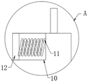
fig. 3 is a schematic view of a partial structure a of the present invention.
In the figure: 1. a lower die holder; 2. a profiled groove; 3. a spring post; 4. sleeving a column; 5. an upper die holder; 6. a connecting seat; 7. a base plate; 8. pressing a plate; 9. a fixed seat; 10. a groove; 11. a spring; 12. a connecting plate; 13. a limiting groove; 14. a material groove; 15. and (4) a die handle.
Detailed Description
The technical solutions in the embodiments of the present invention will be described clearly and completely with reference to the accompanying drawings in the embodiments of the present invention, and it is obvious that the described embodiments are only some embodiments of the present invention, not all embodiments. Based on the embodiments in the present invention, all other embodiments obtained by a person skilled in the art without creative work belong to the protection scope of the present invention.
Please refer to fig. 1-3, the utility model provides a stamping die for making plastics inflation piece, including die holder 1 and upper die base 5, type groove 2 has all been seted up to the both sides of die holder 1, be convenient for to die holder 1 installation fixed, save time and labor, the equal fixedly connected with spring post 3 of four corners on 1 top of die holder, the equal swing joint in top of every spring post 3 has sleeve post 4, increase the cushioning nature, improve the punching press quality, the top of every sleeve post 4 all with the top fixed connection of upper die base 5, the both sides of 5 bottoms of upper die base all are pegged graft through spacing groove 13 and are had fixing base 9, avoid the skew to appear in the stamping process, improve production efficiency.
Preferably, the middle part of the bottom end of the upper die holder 5 is fixedly connected with a connecting seat 6, and the bottom end of the connecting seat 6 is fixedly connected with a pressing plate 8 through a backing plate 7 so as to be conveniently inserted into the material groove 14; the two sides of the top end of the fixed seat 9 are fixedly connected with positioning columns, and the two positioning columns are respectively inserted into the connecting seat 6 through the corresponding limiting grooves 13, so that the fixed seat 9 is conveniently limited, and the deviation of the fixed seat 9 during stamping work is avoided; the top end of the fixed seat 9 is provided with a groove 10, and two sides of the groove 10 are elastically connected with connecting plates 12 through a plurality of springs 11, so that the buffering performance of the cushion plate 7 is improved; the middle part of the groove 10 is inserted with the pressing plate 8 through the material groove 14, and the distance between the two connecting plates 12 is slightly smaller than the length of the backing plate 7, so that the stamping work is facilitated; the middle part on 5 tops of upper die base is fixed and is equipped with die shank 15, and a plurality of through-holes have been seted up on the top of die shank 15 bottom, are convenient for be connected with the press through the setting of a plurality of through-holes on the die shank 15.
When the punching die is used specifically, the utility model relates to a punching die for manufacturing plastic expansion sheets, firstly, the lower die holder 1 is joggled with the fixed position of a press machine through the type groove 2, so as to conveniently install and fix the punching die body, then the plastic expansion sheets to be punched are placed in the material groove 14, then the plastic expansion sheets are connected with the press machine through the arrangement of a plurality of through holes on the die shank 15, when the press machine works, the upper die holder 5 drives the connecting seat 6, the backing plate 7 and the pressing plate 8 to press downwards simultaneously, because the arrangement of the spring columns 3 increases the buffer property between the lower die holder 1 and the upper die holder 5, when the upper die holder 5 presses downwards, the fixing seat 9 is limited conveniently through two positioning columns, so as to avoid the deviation of the fixing seat 9, then the backing plate 7 reaches the position of the groove 10, through extruding the two connecting plates 12, the two connecting plates 12 respectively extrude a plurality of springs 11 at, the plastic expansion sheet is prevented from being damaged during downward stamping, and the pressing plate 8 performs stamping operation on the plastic expansion sheet in the material groove 14, so that the stamping operation is realized.
In the description of the present invention, it should be understood that the indicated orientation or positional relationship is based on the orientation or positional relationship shown in the drawings, and is only for convenience of description and simplification of description, and does not indicate or imply that the indicated device or element must have a particular orientation, be constructed and operated in a particular orientation, and thus should not be construed as limiting the present invention.
In the present invention, unless otherwise explicitly specified or limited, for example, it may be fixedly connected, detachably connected, or integrated; can be mechanically or electrically connected; they may be directly connected or indirectly connected through an intermediate medium, and may be connected through the inside of two elements or in an interaction relationship between two elements, unless otherwise specifically defined, and the specific meaning of the above terms in the present invention will be understood by those skilled in the art according to specific situations.
Although embodiments of the present invention have been shown and described, it will be appreciated by those skilled in the art that changes, modifications, substitutions and alterations can be made in these embodiments without departing from the principles and spirit of the invention, the scope of which is defined in the appended claims and their equivalents.
Claims (6)
1. The utility model provides a stamping die for making plastics inflation piece, includes die holder (1) and upper die base (5), its characterized in that, type groove (2) have all been seted up to the both sides of die holder (1), the equal fixedly connected with spring post (3) of four corners on die holder (1) top, every the equal swing joint in top of spring post (3) has sleeve post (4), every the top of sleeve post (4) all with the top fixed connection of upper die base (5), the both sides of upper die base (5) bottom all are pegged graft through spacing groove (13) and are had fixing base (9).
2. The stamping die for manufacturing the plastic expansion sheet as claimed in claim 1, wherein the middle part of the bottom end of the upper die holder (5) is fixedly connected with a connecting seat (6), and the bottom end of the connecting seat (6) is fixedly connected with a pressing plate (8) through a backing plate (7).
3. The stamping die for manufacturing the plastic expansion sheet as claimed in claim 1, wherein two sides of the top end of the fixing seat (9) are fixedly connected with positioning columns, and the two positioning columns are respectively inserted into the connecting seat (6) through corresponding limiting grooves (13).
4. The stamping die for manufacturing the plastic expansion sheet as claimed in claim 1, wherein the top end of the fixed seat (9) is provided with a groove (10), and both sides of the groove (10) are elastically connected with a connecting plate (12) through a plurality of springs (11).
5. The stamping die for manufacturing the plastic expansion sheet as claimed in claim 4, wherein the middle part of the groove (10) is inserted into the pressing plate (8) through a material groove (14), and the distance between the two connecting plates (12) is slightly smaller than the length of the backing plate (7).
6. The stamping die for manufacturing the plastic expansion sheet as claimed in claim 1, wherein a die handle (15) is fixedly arranged in the middle of the top end of the upper die base (5), and a plurality of through holes are formed in the top end of the bottom of the die handle (15).
Priority Applications (1)
| Application Number | Priority Date | Filing Date | Title |
|---|---|---|---|
| CN201922372489.6U CN211467111U (en) | 2019-12-26 | 2019-12-26 | Stamping die for manufacturing plastic expansion sheet |
Applications Claiming Priority (1)
| Application Number | Priority Date | Filing Date | Title |
|---|---|---|---|
| CN201922372489.6U CN211467111U (en) | 2019-12-26 | 2019-12-26 | Stamping die for manufacturing plastic expansion sheet |
Publications (1)
| Publication Number | Publication Date |
|---|---|
| CN211467111U true CN211467111U (en) | 2020-09-11 |
Family
ID=72368016
Family Applications (1)
| Application Number | Title | Priority Date | Filing Date |
|---|---|---|---|
| CN201922372489.6U Active CN211467111U (en) | 2019-12-26 | 2019-12-26 | Stamping die for manufacturing plastic expansion sheet |
Country Status (1)
| Country | Link |
|---|---|
| CN (1) | CN211467111U (en) |
Cited By (1)
| Publication number | Priority date | Publication date | Assignee | Title |
|---|---|---|---|---|
| WO2022110334A1 (en) * | 2020-11-24 | 2022-06-02 | 山东无棣海丰电缆有限公司 | Plastic extrusion die for cable production |
-
2019
- 2019-12-26 CN CN201922372489.6U patent/CN211467111U/en active Active
Cited By (1)
| Publication number | Priority date | Publication date | Assignee | Title |
|---|---|---|---|---|
| WO2022110334A1 (en) * | 2020-11-24 | 2022-06-02 | 山东无棣海丰电缆有限公司 | Plastic extrusion die for cable production |
Similar Documents
| Publication | Publication Date | Title |
|---|---|---|
| CN211467111U (en) | Stamping die for manufacturing plastic expansion sheet | |
| CN215355681U (en) | Stamping die capable of synchronously punching multiple surfaces | |
| CN110947801A (en) | Automatic cooling bending machine | |
| CN213196624U (en) | Compact frame anchor clamps | |
| CN209811039U (en) | Sheet metal stamping die | |
| CN110899513A (en) | Stamping die and stamping method for top cover of air conditioner outdoor unit | |
| CN214023060U (en) | Structure for simultaneously stretching multiple convex hulls | |
| CN217343115U (en) | Tapered wedge punching die structure | |
| CN213764937U (en) | Notebook computer bottom plate fixture that punches | |
| CN220515969U (en) | Shell fragment riveting structure of quick type of trading | |
| CN218903329U (en) | Shaping and pressing auxiliary material jig for main board support | |
| CN218505306U (en) | Flower arrangement separating device | |
| CN218426820U (en) | Automatic forming mechanism for net basket | |
| CN211938677U (en) | Stamping die of outer quick-witted top cap of air conditioner | |
| CN216502164U (en) | Rivet pressing jig | |
| CN216267567U (en) | Wellhead fixture device | |
| CN210547366U (en) | Lamp support sheet punching positioning die | |
| CN219074051U (en) | Novel high-efficient hole flanging die | |
| CN220005615U (en) | Composite stamping die | |
| CN214228081U (en) | Brush holder base assembling tool | |
| CN209077581U (en) | A kind of thread plate progressive die | |
| CN211101053U (en) | Forming die with double-cavity structure | |
| CN218692783U (en) | Bending die applied to ultrathin soaking plate | |
| CN218504671U (en) | Die-cut cutting die of dysmorphism plastic uptake goods | |
| CN214022942U (en) | Array type stamping die with any station for automobile parts |
Legal Events
| Date | Code | Title | Description |
|---|---|---|---|
| GR01 | Patent grant | ||
| GR01 | Patent grant |