CN211448595U - Interpolation method well cementation annular space top sealing device - Google Patents
Interpolation method well cementation annular space top sealing device Download PDFInfo
- Publication number
- CN211448595U CN211448595U CN201922043529.2U CN201922043529U CN211448595U CN 211448595 U CN211448595 U CN 211448595U CN 201922043529 U CN201922043529 U CN 201922043529U CN 211448595 U CN211448595 U CN 211448595U
- Authority
- CN
- China
- Prior art keywords
- air bag
- annulus
- drill rod
- chuck
- cementing
- Prior art date
- Legal status (The legal status is an assumption and is not a legal conclusion. Google has not performed a legal analysis and makes no representation as to the accuracy of the status listed.)
- Expired - Fee Related
Links
- 238000007789 sealing Methods 0.000 title claims abstract description 43
- 238000000034 method Methods 0.000 title claims abstract description 24
- 238000002347 injection Methods 0.000 claims abstract description 25
- 239000007924 injection Substances 0.000 claims abstract description 25
- 239000002344 surface layer Substances 0.000 claims abstract description 25
- 230000007246 mechanism Effects 0.000 claims abstract description 10
- 230000001174 ascending effect Effects 0.000 claims abstract description 8
- 238000009434 installation Methods 0.000 claims abstract description 4
- 210000004907 gland Anatomy 0.000 claims 2
- 238000005553 drilling Methods 0.000 abstract description 25
- 239000000243 solution Substances 0.000 description 6
- 239000012634 fragment Substances 0.000 description 4
- 230000009286 beneficial effect Effects 0.000 description 3
- 230000008569 process Effects 0.000 description 3
- 239000004568 cement Substances 0.000 description 2
- 238000007667 floating Methods 0.000 description 2
- 239000000463 material Substances 0.000 description 2
- 230000004048 modification Effects 0.000 description 2
- 238000012986 modification Methods 0.000 description 2
- 238000012856 packing Methods 0.000 description 2
- 230000008719 thickening Effects 0.000 description 2
- XLYOFNOQVPJJNP-UHFFFAOYSA-N water Substances O XLYOFNOQVPJJNP-UHFFFAOYSA-N 0.000 description 2
- 230000008859 change Effects 0.000 description 1
- 238000005345 coagulation Methods 0.000 description 1
- 238000010276 construction Methods 0.000 description 1
- 125000004122 cyclic group Chemical group 0.000 description 1
- 238000010586 diagram Methods 0.000 description 1
- 238000005516 engineering process Methods 0.000 description 1
- 238000001125 extrusion Methods 0.000 description 1
- 230000006872 improvement Effects 0.000 description 1
- 210000002445 nipple Anatomy 0.000 description 1
- 230000002265 prevention Effects 0.000 description 1
- 230000009467 reduction Effects 0.000 description 1
- 238000003466 welding Methods 0.000 description 1
Images

Abstract
The utility model discloses an interpolation method well cementation annular space top seal device, include: and the air bag is of an annular structure and surrounds the outer wall of the drill rod. The outer ring surface course of the air bag is designed into a thickened outer side sealing rubber sheet. The inner ring surface layer of the air bag is designed into a thickened inner side sealing rubber sheet. And the upper end surface of the air bag is provided with an air injection hole, and the air injection hole is connected with an air injection pipe. The air bag is provided with an opening which can be cut off and is convenient to install. And the air bag axial limiting mechanism is sleeved on the drill rod and limits the axial ascending and descending of the air bag. The utility model discloses simple installation is swift, and easy operation can install in the optional position of drilling rod body, can be fast effectual sealed drilling rod and sheathed tube annular space, still can safe cementing under the condition that the plug became invalid, reduces the fault loss of interpolation method well cementation, improves the well cementation success rate.
Description
Technical Field
The utility model belongs to the technical field of the oil field exploration drilling technique and specifically relates to an interpolation method well cementation annular space top sealing device.
Background
In the process of oil field exploration and well drilling, a well field adopts an interpolation method to fix a well, and the inevitable occurrence of a plug seal failure fault leads to the failure of well fixing, even the occurrence of a vicious accident that cement flash-coagulation fixes a drilling tool and cannot be raised. In order to solve the problems, the sealing performance of a plug is improved and a top annular sealing device is designed at present, but the problems that the plug fails in an interpolation method due to the complex pressure change and complex installation of the top sealing device in the well cementation process are not well solved, so that great economic loss is caused when the well cementation fault occurs.
Application No.: 201620484932.2, filing date: 2016-05-25 an interpolation method well cementation process structure, including the casing pipe arranged outside, guide shoe installed at bottom of casing pipe, drilling rod and well head sealing means arranged at top of casing pipe; the wellhead sealing device is used for realizing the sealing between the drill rod and the casing pipe; the bottom of the drill rod is not contacted with the guide shoe. The technical structure of the well cementation by the interpolation method can finish the well cementation without using a floating hoop, and avoids the consequence caused by the matching failure between the plug of a drilling tool and the socket of the floating hoop.
Application No.: 201620484808.6, filing date: 2016-05-25 discloses a sealing device for use in an infill well, forming a seal between a casing and a drill pipe; the sealing device comprises an upper flange, a lower flange and an annular sealing gasket arranged between the upper flange and the lower flange, wherein the upper flange and the lower flange are connected together through a bolt; the diameter of the upper flange is larger than that of the sleeve, and a female buckle matched with the male buckle of the drill rod is arranged on the inner side of the upper flange; a male buckle matched with the drill rod female buckle is arranged on the lower side of the middle part of the lower flange; meanwhile, the outer side surface of the lower flange is a conical surface which is matched with the top surface of the sleeve; a sealing gasket I is also arranged between the lower flange and the sleeve. The device realizes the sealing between the casing and the drill rod by a simple structure, has simple operation, can effectively improve the safety of the interpolation well cementation construction, and can adapt to the interpolation well cementation of a shallow large-size casing.
Application No.: 201320099191.2, filing date: 2013-03-05 relates to a well-cementing wellhead tool adopting an interpolation method, belongs to the technical field of oil drilling, well-cementing and cementing tools, and comprises a seat sealing joint, a locking cap and a body; the seat sealing joint is of a tubular structure, the center of the seat sealing joint is provided with a through hole, the upper end of the through hole is provided with an internal thread, the lower end of the through hole is provided with an external thread, and the middle part of the outer wall of the seat sealing joint is provided with a flange with a conical surface; the locking cap is of a tubular structure, and the middle lower part of the excircle of the locking cap is provided with an external thread; the body is of a cylindrical structure, the center of the body is a through hole with a conical surface, the outer lower end of the body is provided with external threads, and a right-angle through hole is formed between the outer wall and the lower end surface; the outer flange of the seat seal joint is arranged in the body and is axially positioned between the inner conical surface of the body and the lower end surface of the locking cap; the body sealing gasket is positioned at the root part of the external thread of the body; the utility model has the advantages that: the structure is reasonable, the operation is simple and convenient, the function is reliable, the operation intensity of the well cementation and water injection operation of the interpolation method can be reduced, the operation efficiency is improved, and the one-time success rate of the well cementation and water injection operation of the interpolation method is ensured.
Application No.: 200520093859.8 application date: 2005-11-24 relate to a salvageable socket type non-plug cementing device used for oil and geological drilling cementing. The inner tube cementing tool seat is placed on the socket, the outer tube is matched with the snap spring to form a tilting prevention mechanism, the socket is fixed on the outer tube through the locking block on the bottom step of the inner tube, the lower part of the socket is connected with the lower joint, the inner lining tube is fixed with the snap spring fixing sleeve, the inner lining tube is connected with the snap spring fixing sleeve, the inner tube upper joint and the inner connecting tube, the hanging seat nipple is connected with the hanging seat, the length adjusting tube is connected with the guide shoe through threads, and the hanging seat key is fixed on the guide shoe through a pin. The device solves the problems that a large well casing and a cement plug drill together and a drilling plug is easy to damage and drop a drilling tool after cementing a small well in the prior art. The utility model discloses can be used to in the oil geology probing well cementation operation.
Application No.: 201520792823.2, filing date: 2015-10-14 relates to choked flow leak protection well cementation device, including the bucket wall, the bucket wall lower extreme is equipped with the base, the inboard symmetry of bucket wall is equipped with the shell fragment, be equipped with the spring between shell fragment and the bucket wall, both ends symmetry is equipped with the pipe about the shell fragment, the pipe outside is equipped with the motor, the symmetry is equipped with the connecting rod between motor and the pipe, the connecting rod upside is equipped with the gasbag, the gasbag upside is equipped with the connecting pipe, the connecting pipe upside is equipped with the inflation pump. The utility model discloses a set up the pipe, can be with the even spout into of whitewashing, increaseed the homogeneity of whitewashing concentration, through setting up the motor, alleviateed the manpower, saved operating time, through setting up the gasbag, can fix the bucket wall well, reduced the unnecessary loss, through setting up the shell fragment, make the pipeline speed reduction well, reduced intensity of labour, increased work efficiency.
Technical scheme and the technical problem that will solve and the beneficial effect who produces of above disclosure technique all with the utility model discloses inequality, to the utility model discloses more technical characteristics and the technical problem and the beneficial effect that will solve all do not have the technological inspiration in the above technical document that discloses.
SUMMERY OF THE UTILITY MODEL
An object of the utility model is to provide an interpolation method well cementation annular space top sealing device, the simple installation is swift, easy operation, can install the optional position at the drilling rod body, can be quick effectual sealed drilling rod and sheathed tube annular space, still can the safety cementing under the condition that the plug became invalid, reduces the fault loss of interpolation method well cementation, improves the well cementation success rate.
In order to achieve the above purpose, the utility model adopts the following technical scheme:
an interpolation cementing annulus top seal device comprising:
and the air bag is of an annular structure and surrounds the outer wall of the drill rod. And the upper end surface of the air bag is provided with an air injection hole, and the air injection hole is connected with an air injection pipe.
And the air bag axial limiting mechanism is sleeved on the drill rod and limits the axial ascending and descending of the air bag.
Further, the outer ring surface layer of the air bag is designed into a thickened outer side sealing rubber sheet. The inner ring surface layer of the air bag is designed into a thickened inner side sealing rubber sheet.
Further, the air bag is designed with an opening which can be cut off and is convenient to install.
Further, the opening is an S-shaped bevel opening.
Further, gasbag axial stop gear includes:
the upper chuck is arranged on the drill rod and is positioned above the air bag, the outer diameter of the upper chuck is smaller than the inner diameter of the sleeve, and the outer diameter of the upper chuck is larger than the inner diameter of an inner ring surface layer of the air bag;
and the lower chuck is arranged on the drill rod and is positioned below the air bag, the outer diameter of the lower chuck is smaller than the inner diameter of the sleeve, and the outer diameter of the lower chuck is larger than the inner diameter of the inner ring surface layer of the air bag.
Further, the upper chuck comprises an upper left semicircular clamping piece and an upper right semicircular clamping piece which are buckled together.
Furthermore, the upper left semicircular clamping piece and the upper right semicircular clamping piece are simultaneously provided with corresponding connecting holes and are fixedly connected through bolts.
Furthermore, the inner walls of the upper left semicircular clamping piece and the upper right semicircular clamping piece are respectively provided with a zigzag clamping tooth which is inclined upwards.
Compared with the prior art, the utility model following beneficial effect has:
the utility model discloses upper and lower chuck is the biplate formula design, detains biplate chuck on the drilling rod body during the use, connects with fastening bolt, and the inboard design of chuck has zigzag card tooth, prevents reciprocating of chuck, lays cyclic annular sealed gasbag in the middle of the chuck from top to bottom, and the well cementation drilling tool is transferred and is targetting in place the back, through the air cock to injecting compressed air in the gasbag, the gasbag stops under the chuck from top to bottom and produces the extrusion to inside pipe wall and drilling rod body, reaches the purpose in sealed ring type space.
The utility model is used for annular space between seal bushing and the drilling rod when interpolation method well cementation can install the optional position at the drilling rod body, does not receive the restriction of putting into, and the big commonality of shutoff scope is good, simple structure, easy and simple to handle, the function is reliable, reduces the well cementation risk that the plug seal became invalid, improves the success rate of one time of interpolation method well cementation.
Drawings
FIG. 1 is a schematic structural diagram of an annular top sealing device for well cementation by an interpolation method according to the present invention;
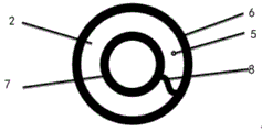
fig. 2 is a plan view of the airbag.
In the figure: 1. the device comprises an upper chuck, 2 parts of an air bag, 3 parts of a lower chuck, 4 parts of a connecting hole, 5 parts of an air injection hole, 6 parts of an outer side sealing rubber sheet, 7 parts of an inner side sealing rubber sheet, 8 parts of an S-shaped inclined plane opening, and 9 parts of sawtooth-shaped clamping teeth.
Detailed Description
The technical solutions in the embodiments of the present invention will be described clearly and completely with reference to the accompanying drawings in the embodiments of the present invention, and it is obvious that the described embodiments are only some embodiments of the present invention, not all embodiments. Based on the embodiments in the present invention, all other embodiments obtained by a person skilled in the art without creative work belong to the protection scope of the present invention.
Example 1:
referring to fig. 1 to 2, the present invention provides a technical solution:
an interpolation cementing annulus top seal device comprising:
and the air bag 2 is of an annular structure and surrounds the outer wall of the drill rod.
Further, the outer ring surface layer of the air bag is designed into a thickened outer side sealing rubber sheet 6.
Further, the inner ring surface layer of the air bag is designed into a thickened inner side sealing rubber 7.
Furthermore, an air injection hole 5 is arranged on the upper end surface of the air bag and is connected with an air injection pipe.
Further, the air bag is designed with an opening which can be cut off and is convenient to install.
Further, the opening is an S-shaped bevel opening 8.
Further, still include:
and the air bag axial limiting mechanism is sleeved on the drill rod and limits the axial ascending and descending of the air bag.
Further, gasbag axial stop gear includes:
the upper chuck 1 is arranged on the drill rod and is positioned above the air bag, the outer diameter of the upper chuck is smaller than the inner diameter of the sleeve, and the outer diameter of the upper chuck is larger than the inner diameter of an inner ring surface layer of the air bag;
and the lower chuck 3 is arranged on the drill rod and is positioned below the air bag, the outer diameter of the lower chuck is smaller than the inner diameter of the sleeve, and the outer diameter of the lower chuck is larger than the inner diameter of the inner ring surface layer of the air bag.
Further, the upper chuck comprises an upper left semicircular clamping piece and an upper right semicircular clamping piece which are buckled together.
Furthermore, the upper left semicircular clamping piece and the upper right semicircular clamping piece are simultaneously provided with corresponding connecting holes 4 and are fixedly connected through bolts.
Furthermore, the inner walls of the upper left semicircular clamping piece and the upper right semicircular clamping piece are respectively provided with a zigzag clamping tooth which is inclined upwards.
Upper and lower chuck respectively comprises two, the lower part is semicircle ring formula baffle, side design connecting hole 4, conveniently use two chucks of bolted connection, the chuck inboard is zigzag calorie of tooth 9, it upwards prevents the chuck to go up along the drilling tool to go up the chuck calorie of tooth, lower chuck structure is the same, the card tooth prevents the chuck to go down along the drilling tool downwards, air bag 2 is the loop configuration, outside design thickening rubber packing 6, thickening rubber packing 8 in the inner circle design, the up end has gas injection hole 5, design S-shaped inclined plane opening 8, with the gasbag disconnection, easy to assemble.
When the drilling tool is used on site, the drilling tool is placed in place, the drilling tool is lifted, the lower chuck 3 is installed at a proper position, the two lower chucks are fastened by the connecting bolt, the sealing air bag 2 is sleeved on the upper body of the drilling rod through the S-shaped inclined plane opening and is tightly attached to the lower chuck, the upper chuck 1 is installed on the sealing air bag in a tightly attached mode, the two chucks are fixed by the connecting bolt, the air injection pipeline is connected with the air injection hole 5, then the drilling tool is placed to sit the inner plug, the air bag is arranged at the position of the casing body, after the downward pressing and suspending weight are completed, air with certain pressure is injected into the air bag, the air bag 2 is expanded, the outer side sealing rubber sheet 6 is tightly attached to the inner wall of the casing, the inner side sealing rubber sheet 7 is tightly attached.
The utility model has the advantages that: the plug-in well cementing device has the advantages of simple structure, simplicity and convenience in operation and reliable function, and can effectively seal the annular space between the drill rod and the casing pipe when the plug-in well cementing is carried out, reduce the well cementing risk of the sealing failure of the plug and improve the one-time success rate of the plug-in well cementing.
Example 2:
referring to fig. 1 to 2, the present invention provides a technical solution:
an interpolation cementing annulus top seal device comprising:
and the air bag 2 is of an annular structure and surrounds the outer wall of the drill rod.
Further, the outer ring surface layer of the air bag is designed into a thickened outer side sealing rubber sheet 6.
Further, the inner ring surface layer of the air bag is designed into a thickened inner side sealing rubber 7.
Furthermore, an air injection hole 5 is arranged on the upper end surface of the air bag and is connected with an air injection pipe.
Further, the air bag is designed with an opening which can be cut off and is convenient to install.
Further, the opening is an S-shaped bevel opening 8.
Further, still include:
and the air bag axial limiting mechanism is sleeved on the drill rod and limits the axial ascending and descending of the air bag.
Further, gasbag axial stop gear includes:
the upper chuck 1 is arranged on the drill rod and is positioned above the air bag, the outer diameter of the upper chuck is smaller than the inner diameter of the sleeve, and the outer diameter of the upper chuck is larger than the inner diameter of an inner ring surface layer of the air bag;
and the lower chuck 3 is arranged on the drill rod and is positioned below the air bag, the outer diameter of the lower chuck is smaller than the inner diameter of the sleeve, and the outer diameter of the lower chuck is larger than the inner diameter of the inner ring surface layer of the air bag.
Further, the upper chuck comprises an upper left semicircular clamping piece and an upper right semicircular clamping piece which are buckled together.
Furthermore, the upper left semicircular clamping piece and the upper right semicircular clamping piece are simultaneously provided with corresponding connecting holes 4 and are fixedly connected through bolts.
Example 3:
referring to fig. 1 to 2, the present invention provides a technical solution:
an interpolation cementing annulus top seal device comprising:
and the air bag 2 is of an annular structure and surrounds the outer wall of the drill rod.
Further, the outer ring surface layer of the air bag is designed into a thickened outer side sealing rubber sheet 6.
Further, the inner ring surface layer of the air bag is designed into a thickened inner side sealing rubber 7.
Furthermore, an air injection hole 5 is arranged on the upper end surface of the air bag and is connected with an air injection pipe.
Further, the air bag is designed with an opening which can be cut off and is convenient to install.
Further, the opening is an S-shaped bevel opening 8.
Further, still include:
and the air bag axial limiting mechanism is sleeved on the drill rod and limits the axial ascending and descending of the air bag.
Further, gasbag axial stop gear includes:
the upper chuck 1 is arranged on the drill rod and is positioned above the air bag, the outer diameter of the upper chuck is smaller than the inner diameter of the sleeve, and the outer diameter of the upper chuck is larger than the inner diameter of an inner ring surface layer of the air bag;
and the lower chuck 3 is arranged on the drill rod and is positioned below the air bag, the outer diameter of the lower chuck is smaller than the inner diameter of the sleeve, and the outer diameter of the lower chuck is larger than the inner diameter of the inner ring surface layer of the air bag.
Further, the upper chuck comprises an upper left semicircular clamping piece and an upper right semicircular clamping piece which are buckled together.
Example 4:
referring to fig. 1 to 2, the present invention provides a technical solution:
an interpolation cementing annulus top seal device comprising:
and the air bag 2 is of an annular structure and surrounds the outer wall of the drill rod.
Further, the outer ring surface layer of the air bag is designed into a thickened outer side sealing rubber sheet 6.
Further, the inner ring surface layer of the air bag is designed into a thickened inner side sealing rubber 7.
Furthermore, an air injection hole 5 is arranged on the upper end surface of the air bag and is connected with an air injection pipe.
Further, the air bag is designed with an opening which can be cut off and is convenient to install.
Further, the opening is an S-shaped bevel opening 8.
Further, still include:
and the air bag axial limiting mechanism is sleeved on the drill rod and limits the axial ascending and descending of the air bag.
Further, gasbag axial stop gear includes:
the upper chuck 1 is arranged on the drill rod and is positioned above the air bag, the outer diameter of the upper chuck is smaller than the inner diameter of the sleeve, and the outer diameter of the upper chuck is larger than the inner diameter of an inner ring surface layer of the air bag;
and the lower chuck 3 is arranged on the drill rod and is positioned below the air bag, the outer diameter of the lower chuck is smaller than the inner diameter of the sleeve, and the outer diameter of the lower chuck is larger than the inner diameter of the inner ring surface layer of the air bag.
Example 5:
referring to fig. 1 to 2, the present invention provides a technical solution:
an interpolation cementing annulus top seal device comprising:
and the air bag 2 is of an annular structure and surrounds the outer wall of the drill rod.
Further, the outer ring surface layer of the air bag is designed into a thickened outer side sealing rubber sheet 6.
Further, the inner ring surface layer of the air bag is designed into a thickened inner side sealing rubber 7.
Furthermore, an air injection hole 5 is arranged on the upper end surface of the air bag and is connected with an air injection pipe.
Further, the air bag is designed with an opening which can be cut off and is convenient to install.
Further, the opening is an S-shaped bevel opening 8.
Further, still include:
and the air bag axial limiting mechanism is sleeved on the drill rod and limits the axial ascending and descending of the air bag.
Although fig. 1 to 2 are used in all the above embodiments, it is obvious to those skilled in the art that separate drawings are not shown as long as the parts or structural features missing in the embodiments are removed from the drawings. As will be clear to the skilled person. Of course, the embodiments with more components are only the preferred embodiments, and the embodiments with fewer components are the basic embodiments, but the basic objects of the invention can also be achieved, so all of them are within the protection scope of the present invention.
All parts and parts which are not discussed in the present application and the connection mode of all parts and parts in the present application belong to the known technology in the technical field, and are not described again. Such as welding, threaded connections, etc.
In the present application, the term "plurality" means two or more unless expressly defined otherwise. The terms "mounted," "connected," "fixed," and the like are to be construed broadly, and for example, "connected" may be a fixed connection, a removable connection, or an integral connection; "coupled" may be direct or indirect through an intermediary. The specific meaning of the above terms in the present invention can be understood according to specific situations by those skilled in the art.
In the description of the present invention, it should be understood that the terms "upper", "lower", "left", "right", "front", "back", and the like indicate orientations or positional relationships based on the orientations or positional relationships shown in the drawings, and are only for convenience of description and simplification of description, but do not indicate or imply that the device or unit indicated must have a specific direction, be constructed and operated in a specific orientation, and therefore, should not be construed as limiting the present invention.
In the description of the present specification, the description of the terms "one embodiment," "some embodiments," "specific embodiments," etc., means that a particular feature, structure, material, or characteristic described in connection with the embodiment or example is included in at least one embodiment or example of the invention. In this specification, the schematic representations of the terms used above do not necessarily refer to the same embodiment or example. Furthermore, the particular features, structures, materials, or characteristics described may be combined in any suitable manner in any one or more embodiments or examples.
The above description is only a preferred embodiment of the present invention and is not intended to limit the present invention, and various modifications and changes may be made by those skilled in the art. Any modification, equivalent replacement, or improvement made within the spirit and principle of the present invention should be included in the protection scope of the present invention.
Claims (7)
1. An interpolation cementing annulus top seal device, comprising:
the air bag is of an annular structure and surrounds the outer wall of the drill rod; the upper end surface of the air bag is provided with a gas injection hole, and the gas injection hole is connected with a gas injection pipe;
and the air bag axial limiting mechanism is sleeved on the drill rod and limits the axial ascending and descending of the air bag.
2. An annulus gland device for annulus cementing according to claim 1, wherein the outer facing of the air bag is designed as a thickened outer stripper rubber and the inner facing of the air bag is designed as a thickened inner stripper rubber.
3. An annulus gland with interpositioning cementing according to claim 2, wherein the bladder is designed with openings to allow the bladder to be disconnected for easy installation.
4. An annulus overseal interpolation method as in claim 3 wherein the opening is an S-shaped beveled opening.
5. An internally cementing annulus overseal as in claim 1 or 2 or 3 or 4 wherein the balloon axial stop mechanism comprises:
the upper chuck is arranged on the drill rod and is positioned above the air bag, the outer diameter of the upper chuck is smaller than the inner diameter of the sleeve, and the outer diameter of the upper chuck is larger than the inner diameter of an inner ring surface layer of the air bag;
and the lower chuck is arranged on the drill rod and is positioned below the air bag, the outer diameter of the lower chuck is smaller than the inner diameter of the sleeve, and the outer diameter of the lower chuck is larger than the inner diameter of the inner ring surface layer of the air bag.
6. An annulus overseal interpolation cementing annulus set according to claim 5 wherein the upper chuck includes left and right upper semicircular tabs that snap together.
7. The annulus top sealing device for well cementation by the interpolation method as claimed in claim 6, wherein the upper left semicircle clamping piece and the upper right semicircle clamping piece are provided with corresponding connecting holes at the same time and are fixed by bolts.
Priority Applications (1)
| Application Number | Priority Date | Filing Date | Title |
|---|---|---|---|
| CN201922043529.2U CN211448595U (en) | 2019-11-21 | 2019-11-21 | Interpolation method well cementation annular space top sealing device |
Applications Claiming Priority (1)
| Application Number | Priority Date | Filing Date | Title |
|---|---|---|---|
| CN201922043529.2U CN211448595U (en) | 2019-11-21 | 2019-11-21 | Interpolation method well cementation annular space top sealing device |
Publications (1)
| Publication Number | Publication Date |
|---|---|
| CN211448595U true CN211448595U (en) | 2020-09-08 |
Family
ID=72297340
Family Applications (1)
| Application Number | Title | Priority Date | Filing Date |
|---|---|---|---|
| CN201922043529.2U Expired - Fee Related CN211448595U (en) | 2019-11-21 | 2019-11-21 | Interpolation method well cementation annular space top sealing device |
Country Status (1)
| Country | Link |
|---|---|
| CN (1) | CN211448595U (en) |
Cited By (2)
| Publication number | Priority date | Publication date | Assignee | Title |
|---|---|---|---|---|
| CN111894511A (en) * | 2020-09-14 | 2020-11-06 | 西南石油大学 | Drilling downhole blowout prevention simulation device |
| CN112096363A (en) * | 2020-09-28 | 2020-12-18 | 中国地质大学(北京) | Liquid nitrogen injection freeze-drying coal bed gas production increasing system and working method thereof |
-
2019
- 2019-11-21 CN CN201922043529.2U patent/CN211448595U/en not_active Expired - Fee Related
Cited By (3)
| Publication number | Priority date | Publication date | Assignee | Title |
|---|---|---|---|---|
| CN111894511A (en) * | 2020-09-14 | 2020-11-06 | 西南石油大学 | Drilling downhole blowout prevention simulation device |
| CN112096363A (en) * | 2020-09-28 | 2020-12-18 | 中国地质大学(北京) | Liquid nitrogen injection freeze-drying coal bed gas production increasing system and working method thereof |
| CN112096363B (en) * | 2020-09-28 | 2021-06-22 | 中国地质大学(北京) | Liquid nitrogen injection freeze-drying coal bed gas production increasing system and working method thereof |
Similar Documents
| Publication | Publication Date | Title |
|---|---|---|
| CN211448595U (en) | Interpolation method well cementation annular space top sealing device | |
| CN103470214B (en) | Multistage hydraulic bridging plug seating and sealing unit | |
| CN207080207U (en) | A kind of oil field is every excavating technology tubing string | |
| CN210195805U (en) | Gas drainage drilling hole sealing device | |
| CN210770887U (en) | Quick-operation joint convenient to installation | |
| CN107740683A (en) | A kind of electric submersible pump mining device for adapting to coiled tubing completion | |
| CN201730579U (en) | High-temperature resistant well control device for double-pipe operation in horizontal wells | |
| CN204879267U (en) | Oil field well head sleeve pipe injecting glue leaking stoppage ware | |
| CN206568080U (en) | A kind of recyclable underwater connector installation tool | |
| CN211008561U (en) | Mechanical packer | |
| CN202946070U (en) | Hydraulic rotating invertedly-buckled releasing tool | |
| CN110469290A (en) | Leakproof two-stage water injection packer | |
| CN103712014B (en) | A kind of deepwater multi-loop connects terminal | |
| CN216894317U (en) | Oil field borehole operation fishing device | |
| CN207437022U (en) | A kind of electric submersible pump mining device for adapting to coiled tubing completion | |
| CN203008833U (en) | Expansion type suspension device of screen pipe well completion | |
| CN216110626U (en) | Hydraulic wellhead sealer | |
| CN211924665U (en) | Steel conduit pipe fitting connecting device | |
| CN210918970U (en) | Acidification packer | |
| CN2625569Y (en) | Impacting shearing device for tail pipe well completion | |
| CN209469412U (en) | A kind of balanced type fracturing packer | |
| CN104912507A (en) | Underwater horizontal Christmas tree body center hole sealing device | |
| CN106948764B (en) | Connecting device for deep water oil gas test pipe column safety control system | |
| CN204782900U (en) | Body centre bore sealing device is set to horizontal production tree under water | |
| CN220434703U (en) | Running tool for installing sleeve mandrel hanger and sealing device at one time |
Legal Events
| Date | Code | Title | Description |
|---|---|---|---|
| GR01 | Patent grant | ||
| GR01 | Patent grant | ||
| CF01 | Termination of patent right due to non-payment of annual fee |
Granted publication date: 20200908 |
|
| CF01 | Termination of patent right due to non-payment of annual fee |