CN211444279U - Intelligent robot car unloader - Google Patents
Intelligent robot car unloader Download PDFInfo
- Publication number
- CN211444279U CN211444279U CN201921700652.0U CN201921700652U CN211444279U CN 211444279 U CN211444279 U CN 211444279U CN 201921700652 U CN201921700652 U CN 201921700652U CN 211444279 U CN211444279 U CN 211444279U
- Authority
- CN
- China
- Prior art keywords
- seat
- gear
- base
- grain
- cantilever
- Prior art date
- Legal status (The legal status is an assumption and is not a legal conclusion. Google has not performed a legal analysis and makes no representation as to the accuracy of the status listed.)
- Active
Links
Images


Abstract
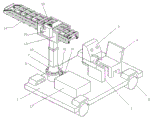
The utility model relates to the technical field of grain unloading machinery, in particular to an intelligent robot car unloader, which comprises a base, wheels are arranged at the front end and the rear end of the lower surface of the base, a driving seat for controlling the wheels is arranged on the upper surface of the base, a seat is fixed on the base at the rear side of the driving seat, a control cabinet is arranged at the side surface of the seat, a rotary drum is fixed at the front end of the upper surface of the base, a rotary shaft is arranged in the rotary drum, the lower end of the rotary shaft is connected with a first gear, a notch is arranged on the rotary drum at the level of the first gear, and a rotating motor; the utility model discloses can effectively solve a large amount of labours that present manual work unloaded grain and brought, only need the operation personnel to drive whole car unloader when unloading grain, will unload inside the grain cantilever stretches into the car storehouse of transport vechicle, then the harrow board realizes taking off grain fast from car storehouse inside along with the transmission of conveyer belt under driving motor's drive, and it has not only greatly reduced operation personnel's intensity of labour, unloads grain fast moreover.
Description
Technical Field
The utility model relates to a unload grain machinery technical field, concretely relates to intelligent robot car unloader.
Background
In agricultural grain transportation, grains which are scattered on a transport vehicle need to be transported from a vehicle cabin to the ground of the grain cabin. The existing transportation mode is mostly that the manual work unloads bulk grain from the car to the conveyer belt that has the funnel on, during grain carried the granary through the conveyer belt, it not only wastes time and energy, needs the manual work to take off grain to car storehouse mouth to the grain that stores in the car storehouse inside of transport vechicle moreover, then pours it into on the conveyer belt into it again, has greatly increased operation personnel's the amount of labour. At present, there has been the car unloader on the market to be used for unloading the inside grain in car storehouse fast, but its length automatically regulated that can't stretch into the inside grain cantilever length that unloads in car storehouse according to the car storehouse, and its angle and the level that unloads the grain cantilever are fixed moreover, can't be applicable to the grain of unloading of various grain transport vechicles, and its suitability receives very big restriction. Therefore, aiming at the defects of the prior art, the invention provides the intelligent robot car unloader which can effectively solve the defects of the prior car unloader and has wider applicability.
SUMMERY OF THE UTILITY MODEL
The utility model aims to solve the technical problem that an intelligent robot car unloader has been designed for solve the present current transport vechicle on the grain uninstallation the existence the amount of labour is big, application scope is little not enough.
The utility model discloses a realize through following technical scheme:
an intelligent robot car unloader comprises a base, wheels are arranged at the front end and the rear end of the lower surface of the base, a driver seat for controlling the wheels is arranged on the upper surface of the base, a seat is fixed on the base at the rear side of the driver seat, a control cabinet is arranged on the side surface of the seat, a rotary drum is fixed at the front end of the upper surface of the base, a rotary shaft is arranged in the rotary drum, the lower end of the rotary shaft is connected with a first gear, a notch is arranged on the rotary drum at the level of the first gear, a rotary motor is fixed on the lower surface of the base, a reduction box is arranged on a fixed seat right above the rotary motor, an output shaft of the rotary motor penetrates through the base to be connected with the reduction box, a second gear meshed with the first gear through the notch is connected on the output shaft of the reduction box, a hydraulic cylinder is connected at the top end, the inside of cantilever removal seat is provided with can follow cantilever removal seat horizontal migration unload the grain cantilever, it includes the ledge that two symmetries set up to unload the grain cantilever, is located both ends are provided with driven bull stick and initiative bull stick respectively around two ledges, be provided with two conveyer belts between driven bull stick and the initiative bull stick, two be connected with a plurality of vertical rake boards jointly on the conveyer belt, be located be connected with the fixed plate on two ledges under the initiative bull stick, be fixed with driving motor on the fixed plate, be connected with the third gear on driving motor's the output shaft, be connected with the fourth gear with third gear engaged with on the initiative bull stick, the base upper surface still is provided with the battery.
As a further improvement of the proposal, a servo motor is fixed on the upper surface of the cantilever moving seat, a gear transmission box is fixed on the side surface of the cantilever moving seat, the output shaft of the servo motor is connected with the gear transmission box, the output shaft of the gear transmission case penetrates through the end part of the side surface of the cantilever moving seat and is connected with a fifth gear, the wall rack is composed of an upper cross rod, a lower cross rod and a plurality of vertical fixing rods, racks meshed with a fifth gear are arranged on the lower surface of the upper cross rod and the upper surface of the lower cross rod which are positioned between the two adjacent vertical fixing rods, guide rail grooves matched with the upper cross rod and the lower cross rod are arranged on the inner side wall of the cantilever moving seat positioned on the opposite side of the gear transmission case, the fixed distance movement of the whole grain unloading cantilever is realized by controlling the pulse of the servo motor, so that grains at different depths inside the car bin can be unloaded.
As a further improvement of the scheme, be fixed with the buffer block on the conveyer belt, be provided with in the buffer block and rotate the chamber, vertical harrow board rotates and is connected with on the diapire that rotates the chamber, all be connected with the buffer spring who is connected with vertical harrow board on the lateral wall about rotating the chamber, can play the cushioning effect to vertical harrow board, can prevent that the inner wall of vertical harrow board and car storehouse is inconsistent with the harrow board rupture.
As the further improvement of above-mentioned scheme, all be provided with the circle wheel on driven bull stick and the initiative bull stick, evenly seted up a plurality of semicircle tooth's grooves on the circumference side of circle wheel, the lower surface equidistant be provided with semicircle tooth's groove matched with semi-cylindrical sand grip of conveyer belt, through the cooperation of semi-cylindrical sand grip and semicircle tooth's groove, can make conveyer belt steady operation.
As a further improvement of the scheme, the dustproof vehicle cover is arranged on the base outside the seat, the driver seat and the control cabinet, so that the dust can be prevented from being sucked by operating personnel during grain unloading.
Has the advantages that:
the utility model provides a special equipment capable of unloading grain in the car storehouse of a transport vehicle, which can effectively solve the problem of a large amount of labor force caused by the existing manual grain unloading, only needs an operator to drive the whole unloading machine when unloading grain, extends a grain unloading cantilever into the car storehouse of the transport vehicle, and then realizes the fast grain unloading from the inside of the car storehouse by a rake plate driven by a driving motor along with the transmission of a conveyor belt, thereby not only greatly reducing the labor intensity of the operator, but also having fast grain unloading speed; and simultaneously, the utility model discloses an inside inserting the rotary drum with the pivot, can realize unloading 360 rotations of grain cantilever through rotating the motor, can realize unloading the level adjustment of grain cantilever through the effect of pneumatic cylinder, its cantilever removes the seat at last and can also realize unloading the regulation that the grain cantilever stretched into the inside arbitrary length in transport vechicle storehouse through servo motor's fixed number of turns rotation and meshing between fifth gear and the rack, the applicable uninstallation of grain in the transport vechicle of equidimension not, its function is various, it is effectual to unload the grain, can widely use.
Drawings
In order to more clearly illustrate the technical solutions of the embodiments of the present invention, the drawings used in the description of the embodiments will be briefly introduced below, and it is obvious that the drawings in the following description are only some embodiments of the present invention, and it is obvious for those skilled in the art that other drawings can be obtained according to these drawings without creative efforts.
Fig. 1 is a schematic perspective view of the present invention;
FIG. 2 is a schematic view of the three-dimensional structure of the cantilever moving seat and the grain unloading cantilever of the present invention;
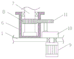
FIG. 3 is a schematic view of the internal plane structure of the middle drum and the rotating shaft of the present invention;
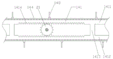
FIG. 4 is a schematic view of the plane structure of the ledge inside the cantilever moving seat according to the present invention;
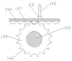
fig. 5 is a schematic view of the plane structure of the junction between the driven rotating rod and the conveyor belt of the present invention.
Fig. 6 is a schematic view of the internal plane structure of the junction between the middle buffer block and the vertical rake plate of the present invention.
Wherein, 1-base, 2-wheel, 3-driver seat, 4-seat, 5-control cabinet, 6-rotary drum, 7-rotary shaft, 8-first gear, 9-rotary motor, 10-reduction box, 11-second gear, 12-hydraulic cylinder, 13-cantilever moving seat, 14-grain unloading cantilever, 15-third gear, 16-fourth gear, 17-accumulator, 18-servo motor, 19-gear box, 20-gear box, 21-fifth gear, 22-guide rail groove, 23-buffer block, 24-buffer spring;
141-ledge, 1411-upper cross bar, 1412-lower cross bar, 1413-vertical fixing rod, 1424-rack, 142-driven rotating rod, 143-driving rotating rod, 144-conveyor belt, 145-round wheel, 146-semicircular tooth groove, 147-semicircular column convex strip, 148-vertical harrow plate and 149-driving motor.
Detailed Description
In order to make the technical solutions better understood by those skilled in the art, the technical solutions in the embodiments of the present application will be clearly and completely described below with reference to the drawings in the embodiments of the present application, and it is obvious that the described embodiments are only partial embodiments of the present application, but not all embodiments. All other embodiments, which can be derived by a person skilled in the art from the embodiments given herein without making any creative effort, shall fall within the protection scope of the present application.
It should be noted that the terms "first," "second," and the like in the description and claims of this application and in the drawings described above are used for distinguishing between similar elements and not necessarily for describing a particular sequential or chronological order. It should be understood that the data so used may be interchanged under appropriate circumstances such that embodiments of the application described herein may be used. Furthermore, the terms "comprises," "comprising," and "having," and any variations thereof, are intended to cover a non-exclusive inclusion, such that a process, method, system, article, or apparatus that comprises a list of steps or elements is not necessarily limited to those steps or elements expressly listed, but may include other steps or elements not expressly listed or inherent to such process, method, article, or apparatus.
In this application, the terms "upper", "lower", "left", "right", "front", "rear", "top", "bottom", "inner", "outer", "middle", "vertical", "horizontal", "lateral", "longitudinal", and the like indicate orientations or positional relationships based on the orientations or positional relationships shown in the drawings. These terms are used primarily to better describe the invention and its embodiments, and are not intended to limit the indicated devices, elements or components to a particular orientation or to be constructed and operated in a particular orientation.
Moreover, some of the above terms may be used to indicate other meanings besides the orientation or positional relationship, for example, the term "on" may also be used to indicate some kind of attachment or connection relationship in some cases. The specific meaning of these terms in the present invention can be understood by those of ordinary skill in the art as appropriate.
Furthermore, the terms "mounted," "disposed," "provided," "connected," and "sleeved" are to be construed broadly. For example, it may be a fixed connection, a removable connection, or a unitary construction; can be a mechanical connection, or an electrical connection; may be directly connected, or indirectly connected through intervening media, or may be in internal communication between two devices, elements or components. The specific meaning of the above terms in the present invention can be understood according to specific situations by those skilled in the art.
It should be noted that the embodiments and features of the embodiments in the present application may be combined with each other without conflict. The present application will be described in detail below with reference to the embodiments with reference to the attached drawings.
The utility model provides an intelligent robot car unloader combines below the figure 1~6 to make following introduction to this implementation. The steering wheel mainly comprises a base 1, wheels 2 are arranged at the front end and the rear end of the lower surface of the base 1, a driver seat 3 for controlling the wheels is arranged on the upper surface of the base 1, and the mode that the driver seat 3 controls the steering of the wheels 2 and specifically drives the wheels 2 is the prior art and is not specifically described here. A seat 4 is fixed to the base 1 at the rear side of the driver seat 3, and a control cabinet 5 is provided on the side surface of the seat 4. In order to prevent operators from sucking a large amount of dust during grain unloading, dustproof car covers (not specifically shown in the figure) are further arranged on the bases outside the seat 4, the driver seat 2 and the control cabinet 5.
The front end of base 1 upper surface is fixed with rotary drum 6, and rotary drum 6 is inside to be provided with pivot 7, realizes being connected through the bearing between its pivot 7 and the rotary drum 6. The lower end of the rotating shaft 7 is connected with a first gear 8, a notch (not marked in the figure) is formed in the rotating drum 6 located at the level of the first gear 8, a rotating motor 9 is fixed on the lower surface of the base 1, a reduction gearbox 10 is arranged on the upper surface of the fixing base 1 located right above the rotating motor 9, an output shaft of the rotating motor 9 penetrates through the base 1 to be connected with the reduction gearbox 10, a second gear 11 is connected to an output shaft of the reduction gearbox 10, and the side surface of the second gear 11 is meshed with the first gear 8 through the notch. The top end of the rotating shaft 7 is connected with a hydraulic cylinder 12, the top end of the hydraulic cylinder 12 is fixedly connected with a cantilever moving seat 13, wherein the inside of the cantilever moving seat 13 is provided with a grain unloading cantilever 14 which can horizontally move along the cantilever moving seat 13, the main structure of the grain unloading cantilever 14 comprises two ledges 141 which are symmetrically arranged, and a driven rotating rod 142 and a driving rotating rod 143 are respectively provided at front and rear ends of the two ledges 141, two belts 144 are provided between the follower link 142 and the driving link 143, in order to ensure the stable transmission of the conveyor belt 144, round wheels 145 are respectively arranged on the driven rotating rod 142 and the driving rotating rod 143, a plurality of semicircular tooth grooves 146 are uniformly arranged on the circumferential side surface of each round wheel 145, and semi-cylindrical protruding strips 147 matched with the semi-circular tooth grooves 146 are arranged on the lower surface of the conveyor belt 144 at equal intervals, the conveyor belt 144 can be stably operated by the action between the semi-cylindrical ribs 147 and the semi-cylindrical teeth grooves 146. A plurality of vertical rake plates 148 are commonly attached to the upper surfaces of the two belts 144. A fixed plate (not labeled in the figure) is connected to the two ledges 141 located right below the driving rotary rod 142, a driving motor 149 is fixed to the fixed plate, a third gear 15 is connected to an output shaft of the driving motor 149, a fourth gear 16 is connected to the driving rotary rod 143, and the driving force of the driving motor 149 is transmitted to the driving rotary rod 143 through the engagement between the third gear 15 and the fourth gear 16, so that the driving of the conveyor belt 144 is realized. Meanwhile, the upper surface of the base 1 is also provided with a storage battery 17, and the storage battery 17 is used as a power supply source of all electric devices on the intelligent robot unloader.
The specific horizontal movement of the grain unloading cantilever 14 in the cantilever moving seat 13 in the embodiment is realized by the following structure: a servo motor 18 is fixed on the upper surface of the cantilever moving seat 13, a gear transmission box 19 is fixed on the side surface of the cantilever moving seat 13, the output shaft of the servo motor 18 is connected with a gear transmission box 20, and the end part of the output shaft of the gear transmission box 20 penetrating through the side surface of the cantilever moving seat 13 is connected with a fifth gear 21. The wall rack 141 is composed of an upper cross rod 1411, a lower cross rod 1412 and a plurality of vertical fixing rods 1413, racks 1414 are arranged on the lower surface of the upper cross rod 1411 and the upper surface of the lower cross rod 1412 between two adjacent vertical fixing rods 1412, wherein a fifth gear 21 is meshed with the racks 1414, a guide rail groove 22 matched with the upper cross rod 1411 and the lower cross rod 1412 is arranged on the inner side wall of the cantilever moving seat 13 at the opposite side of the gear transmission box 20, the structure realizes the fixed-circle movement of the servo motor 18 by controlling the pulse of the servo motor 18, and realizes the fixed-distance movement of the whole grain unloading cantilever 14 by the conversion of the line speed, so that the grain unloading cantilever 14 with the corresponding length can be stretched into according to the actual length inside the transport cart.
Finally, in order to solve the problem that the vertical harrow plate 148 often contradicts with the inner wall of the car cabin to cause the breakage of the vertical harrow plate 148 in the actual grain unloading process, the buffer block 23 is fixed on the conveyor belt 144, the rotating cavity is arranged in the buffer block 23, the vertical harrow plate 148 is rotatably connected to the bottom wall of the rotating cavity, the left side wall and the right side wall of the rotating cavity are both connected with the buffer springs 24 connected with the harrow plate 148, through the improvement of the connection mode between the vertical harrow plate 148 and the conveyor belt 144, a certain buffering effect can be achieved when the vertical harrow plate 148 contradicts with the inner wall of the car cabin, and the harrow plate 148 is effectively prevented from being contradicted with the inner wall of the car cabin to break the harrow plate.
The utility model discloses intelligent robot car unloader grain when unloading grain in the transport vechicle concrete step as follows:
firstly, the operator sits on the seat 4 to control the driver seat 2 to drive the whole intelligent robot unloader to the opening of the car cabin of the grain transport vehicle, and then the length of the hydraulic cylinder 12 is adjusted through the control cabinet 5 according to the actual height of the car cabin, so that the unloading cantilever 14 is at a proper height, and meanwhile, the rotation of the rotating motor 9 is controlled to realize the angle adjustment of the unloading cantilever 14 on the horizontal plane.
After the position adjustment is finished, the driving motor 149 is started, so that the conveyor belt 144 on the unloading cantilever 14 moves to drive the rake plate 148 to move, then the grains in the car bin are unloaded from the car bin through the vertical rake plate 148, after the grain at the outer end of the car bin opening is unloaded, the servo motor is controlled to rotate for a fixed number of turns according to the actual condition control cabinet 5, so that the purpose that the unloading cantilever 14 stretches into the car bin for a fixed length to continue unloading the grains is achieved until the grains are all unloaded, and then the whole intelligent robot unloader is driven to a position far away from the car bin.
The utility model discloses not only can reduce the labour of unloading grain in the transport vechicle, unload grain fast, unload the grain cantilever moreover and can also realize the regulation of different angles on level's regulation, the horizontal plane and can stretch into the length that the car storehouse unloaded the grain cantilever according to actual need and adjust, it unloads grain effectual, is worth wideling popularize and use.
The above description is only exemplary of the present invention and should not be construed as limiting the present invention, and any modifications, equivalents and improvements made within the spirit and principles of the present invention are intended to be included within the scope of the present invention.
Claims (5)
1. An intelligent robot car unloader comprises a base and is characterized in that wheels are arranged at the front end and the rear end of the lower surface of the base, a driver seat for controlling the wheels is arranged on the upper surface of the base, a seat is fixed on the base at the rear side of the driver seat, a control cabinet is arranged on the side face of the seat, a rotary drum is fixed at the front end of the upper surface of the base, a rotary shaft is arranged in the rotary drum, the lower end of the rotary shaft is connected with a first gear, a notch is formed in the rotary drum at the level of the first gear, a rotary motor is fixed on the lower surface of the base, a reduction gearbox is arranged on a fixed seat right above the rotary motor, an output shaft of the rotary motor penetrates through the base to be connected with the reduction gearbox, a second gear meshed with the first gear through the notch is connected on an output shaft of the reduction gearbox, the top fixedly connected with cantilever of pneumatic cylinder removes the seat, the inside that the cantilever removed the seat is provided with can follow cantilever and removes a horizontal migration unload the grain cantilever, it includes the ledge that two symmetries set up to unload the grain cantilever, is located both ends are provided with driven bull stick and initiative bull stick respectively around two ledges, be provided with two conveyer belts between driven bull stick and the initiative bull stick, two be connected with a plurality of vertical harrow boards jointly on the conveyer belt, be located be connected with the fixed plate on two ledges under the initiative bull stick, be fixed with driving motor on the fixed plate, be connected with the third gear on driving motor's the output shaft, be connected with the fourth gear with third gear engaged with on the initiative bull stick, the base upper surface still is provided with the battery.
2. The intelligent robot unloader as recited in claim 1, wherein a servo motor is fixed on the upper surface of the cantilever moving seat, a gear transmission box is fixed on the side surface of the cantilever moving seat, an output shaft of the servo motor is connected with the gear transmission box, a fifth gear is connected to the end part of the output shaft of the gear transmission box, which penetrates through the side surface of the cantilever moving seat, the ledge is composed of an upper cross bar, a lower cross bar and a plurality of vertical fixing bars, racks meshed with the fifth gear are arranged on the lower surface of the upper cross bar and the upper surface of the lower cross bar between the two adjacent vertical fixing bars, and a guide rail groove matched with the upper cross bar and the lower cross bar is arranged on the inner side wall of the cantilever moving seat on the opposite side of the gear transmission box.
3. The intelligent robot car unloader as claimed in claim 1, wherein a buffer block is fixed on the conveyor belt, a rotating cavity is arranged in the buffer block, the vertical harrow plate is rotatably connected to the bottom wall of the rotating cavity, and buffer springs connected with the vertical harrow plate are connected to both the left and right side walls of the rotating cavity.
4. The intelligent robot car unloader as claimed in claim 1, wherein the driven rotating rod and the driving rotating rod are respectively provided with a circular wheel, a plurality of semicircular tooth grooves are uniformly formed on the circumferential side surface of the circular wheel, and the lower surface of the conveyor belt is provided with semi-cylindrical protruding strips matched with the semicircular tooth grooves at equal intervals.
5. The intelligent robot car unloader of claim 1, wherein a dust cover is further provided on the base outside the seat, the driver's seat and the control cabinet.
Priority Applications (1)
| Application Number | Priority Date | Filing Date | Title |
|---|---|---|---|
| CN201921700652.0U CN211444279U (en) | 2019-10-12 | 2019-10-12 | Intelligent robot car unloader |
Applications Claiming Priority (1)
| Application Number | Priority Date | Filing Date | Title |
|---|---|---|---|
| CN201921700652.0U CN211444279U (en) | 2019-10-12 | 2019-10-12 | Intelligent robot car unloader |
Publications (1)
| Publication Number | Publication Date |
|---|---|
| CN211444279U true CN211444279U (en) | 2020-09-08 |
Family
ID=72297197
Family Applications (1)
| Application Number | Title | Priority Date | Filing Date |
|---|---|---|---|
| CN201921700652.0U Active CN211444279U (en) | 2019-10-12 | 2019-10-12 | Intelligent robot car unloader |
Country Status (1)
| Country | Link |
|---|---|
| CN (1) | CN211444279U (en) |
Cited By (1)
| Publication number | Priority date | Publication date | Assignee | Title |
|---|---|---|---|---|
| CN110654897A (en) * | 2019-10-12 | 2020-01-07 | 界首市金龙机械设备有限公司 | Intelligent robot car unloader |
-
2019
- 2019-10-12 CN CN201921700652.0U patent/CN211444279U/en active Active
Cited By (1)
| Publication number | Priority date | Publication date | Assignee | Title |
|---|---|---|---|---|
| CN110654897A (en) * | 2019-10-12 | 2020-01-07 | 界首市金龙机械设备有限公司 | Intelligent robot car unloader |
Similar Documents
| Publication | Publication Date | Title |
|---|---|---|
| CN103406527B (en) | For the device that ladle working lining is built by laying bricks or stones | |
| CN105621016A (en) | Cyclic material receiving device | |
| CN211444279U (en) | Intelligent robot car unloader | |
| CN210392997U (en) | Propelling movement formula carloader | |
| CN205169771U (en) | Promotion of cigarette frame, transport and buffer memory equipment | |
| CN107764583B (en) | Multifunctional automatic soil sampler | |
| CN213567899U (en) | Automatic loading and unloading device for pressure maintaining box | |
| CN211918709U (en) | Movable processing and transporting device | |
| CN106904392B (en) | Fragment of brick loading and unloading carrier | |
| CN209352169U (en) | Material transferring device and the material transmission line body equipment with it between a kind of wire body | |
| CN109130591B (en) | Cover body conveying and assembling system of full-automatic pencil lead filling machine | |
| CN110654897A (en) | Intelligent robot car unloader | |
| CN208882722U (en) | A kind of conveyer | |
| CN108085647B (en) | A kind of screw transporter for vacuum coating | |
| CN216972018U (en) | Calcium carbide production system | |
| CN109384033A (en) | Material transferring device, material transmission line body equipment and control method between a kind of wire body | |
| CN212374339U (en) | 180 tipping arrangement that conveyer was used | |
| CN109720647A (en) | A kind of unmanned restaurant system of processing and food providing method | |
| CN215466276U (en) | Loading attachment is used in processing of container bottom plate | |
| CN115158953A (en) | Silicon rod storage discharge conveying device and conveying method thereof | |
| CN212831414U (en) | Fork shaft production that stability is high is with fortune material device | |
| CN210913978U (en) | Vertical material conveying device | |
| CN110080542B (en) | Automatic wall brick stacking robot | |
| CN111071699A (en) | Automatic material distributing and feeding method for medical injector needle cylinder | |
| CN110733871A (en) | Material conveying equipment |
Legal Events
| Date | Code | Title | Description |
|---|---|---|---|
| GR01 | Patent grant | ||
| GR01 | Patent grant |