CN211439102U - Automatic material clamping and processing device with liftable platform - Google Patents
Automatic material clamping and processing device with liftable platform Download PDFInfo
- Publication number
- CN211439102U CN211439102U CN201922035584.7U CN201922035584U CN211439102U CN 211439102 U CN211439102 U CN 211439102U CN 201922035584 U CN201922035584 U CN 201922035584U CN 211439102 U CN211439102 U CN 211439102U
- Authority
- CN
- China
- Prior art keywords
- frame
- adjusting screw
- screw rod
- fixedly connected
- clamp
- Prior art date
- Legal status (The legal status is an assumption and is not a legal conclusion. Google has not performed a legal analysis and makes no representation as to the accuracy of the status listed.)
- Active
Links
Images


Abstract
The utility model belongs to the technical field of engraving machines, in particular to an automatic clamping processing device with a liftable platform, which comprises a first frame and a second frame, wherein the bottom of the second frame is provided with symmetrically distributed support rods, the second frame is provided with fixedly connected guide rails, a clamp cylinder mounting plate which is connected in a sliding way is arranged between the guide rails, a plurality of fixedly connected clamp cylinders are arranged on the clamp cylinder mounting plate, the second frame is provided with an adjusting screw rod, the two ends of the adjusting screw rod are fixedly connected with the second frame through the bottom of a mounting block, a slide block screw nut connecting seat which is matched with the adjusting screw rod is arranged on the adjusting screw rod, a connecting synchronous belt is arranged between the adjusting screw rods, a clamp moving motor is arranged on the second frame, the clamp moving motor is connected with the end part of the corresponding adjusting screw rod, a table top which can move up and down is arranged between the support rods and positioned between the, the large-size explosion-proof box can be machined.
Description
Technical Field
The utility model belongs to the technical field of the engraver, concretely relates to automatic material clamping processingequipment of platform liftable.
Background
The common explosion-proof box has more specifications and types, and the explosion-proof box in the market is the mainstream and is mainly drilled by manual operation. Only a portion of the anisotropic holes are machined by a conventional engraving machine.
However, the existing manual processing has low hole opening efficiency, poor product consistency and high danger;
the conventional engraving machine has the disadvantages that the feeding height is low, and the processing of an explosion-proof box with large specification cannot be met; meanwhile, the tooling fixtures cannot be unified during machining, and the universality is poor.
Therefore, aiming at the related problems of the existing explosion-proof box opening, the applicant designs a device which can fill the blank that the conventional machine type cannot process the explosion-proof box with large size, and simultaneously, an automatic material clamping device is added to solve the problem of product fixation.
SUMMERY OF THE UTILITY MODEL
The prior art is difficult to satisfy people's needs, in order to solve the above-mentioned problem that exists, the utility model provides an automatic material processingequipment that presss from both sides of platform liftable.
In order to achieve the above object, the utility model provides a following technical scheme:
the utility model provides an automatic material processingequipment that presss from both sides of platform liftable which characterized in that: the automatic clamp device comprises a first frame and a second frame, wherein the first frame and the second frame are respectively two, two parallel ends of the second frame are fixedly connected through the first frame, the bottom of the second frame is provided with symmetrically distributed support rods, the second frame is provided with fixedly connected guide rails, a clamp cylinder mounting plate in sliding connection is arranged between the adjacent guide rails, the clamp cylinder mounting plate is provided with a plurality of fixedly connected clamp cylinders, the second frame is provided with an adjusting screw rod, two ends of the adjusting screw rod are provided with movably connected mounting blocks, the bottom of each mounting block is fixedly connected with the second frame, the adjusting screw rod penetrates through the bottom of the corresponding guide rail, a slide block and screw connecting seat matched with the adjusting screw rod is arranged on the adjusting screw rod, the slide block and screw connecting seat is fixedly connected with the bottom of the corresponding guide rail, and a connected synchronous belt is arranged between the adjacent adjusting screw rods, the clamp moving motor is arranged on the second rack and connected with the end portion of the corresponding adjusting screw rod, a table top capable of moving up and down is arranged between the supporting rods and located between the guide rails, and a lifting mechanism connected with the table top is arranged at the bottom of the table top.
Preferably, a plurality of positioning rings fixedly connected are arranged on the inner side of the second rack, guide pillars are arranged in the positioning rings, and the middle parts of the guide pillars movably penetrate through the table board.
Furthermore, the lifting mechanism adopts an electric movable hydraulic scissor type lifter
Preferably, the lifting mechanism adopts 4 linkage ball screw lifters in the prior art,
preferably, the end part of the adjusting screw rod is provided with a coupler, and the output end of the clamp moving motor is connected with the coupler.
The working principle is as follows: the movable clamp mainly realizes the movement of the clamp through two screw rods, and the screw and the sliding block are connected through the sliding block screw nut connecting seat. The clamp moving motor is used as a power source to drive one lead screw to rotate, and the other lead screw is driven by the synchronous belt, so that the clamp cylinder mounting plate can move. The clamp cylinder is fixed on the clamp cylinder mounting plate through bolts, and clamping during product processing is achieved through combination of movement.
Compared with the prior art, the beneficial effects of the utility model are that:
the clamping device comprises a clamping cylinder mounting plate, a guide rail, a motor, a synchronous belt, a cylinder, a first frame, a second frame, a motor, a clamping cylinder and a motor, wherein the clamping cylinder mounting plate is arranged on the first frame;
meanwhile, the design of the liftable table top can adjust the height of the table top according to the size of a workpiece, so that the large-size explosion-proof box can be machined;
the device can meet the requirements of processing round holes and special-shaped holes; the processing efficiency and the product quality of the product are improved; the whole machine has strong universality, replaces manpower, and improves product benefits; the movable clamp has strong universality and can clamp products of various specifications.
Drawings
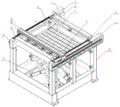
Fig. 1 is a schematic view of a front view structure provided in embodiment 1 of the present invention;
fig. 2 is an enlarged schematic view of a position a provided in embodiment 1 of the present invention;
fig. 3 is an enlarged schematic view of a position B provided in embodiment 1 of the present invention;
fig. 4 is a schematic view of a connection structure of a clamp moving motor and an adjusting screw provided in embodiment 1 of the present invention;
fig. 5 is a schematic front view of the structure provided in embodiment 2 of the present invention;
the reference numbers in the figures illustrate: 1. a clamp moving motor; 3. a guide post; 31. a positioning ring; 4. a table top; 5. a synchronous belt; 6. a guide rail; 8. adjusting the screw rod; 81. a slide block screw nut connecting seat; 82. a coupling; 83. mounting blocks; 9. a clamp cylinder mounting plate; 10. a clamp cylinder; 11. 4 linkage ball screw lifters; 12. a first frame; 13. electrically moving a hydraulic scissor lift; 14. a second frame; 15. a support rod.
Detailed Description
In order to make the technical means, creation features, achievement purposes and functions of the present invention easy to understand and understand, the present invention is further explained by combining with the specific drawings.
It should be noted that, in the present invention, when an element is referred to as being "fixed" to another element, it may be directly on the other element or intervening elements may also be present. When an element is referred to as being "connected" to another element, it can be directly connected to the other element or intervening elements may also be present. The terms "vertical," "horizontal," "left," "right," and the like as used herein are for illustrative purposes only and do not denote a unique embodiment.
Unless defined otherwise, all technical and scientific terms used herein have the same meaning as commonly understood by one of ordinary skill in the art to which this invention belongs. The terminology used herein in the description of the invention is for the purpose of describing particular embodiments only and is not intended to be limiting of the invention. As used herein, the term "and/or" includes any and all combinations of one or more of the associated listed items.
Example 1
Referring to fig. 1-4, an automatic material clamping and processing device with a liftable platform comprises a first frame 12 and a second frame 14, wherein the first frame 12 and the second frame 14 are two, two parallel ends of the second frame 14 are fixedly connected through the first frame 12, the bottom of the second frame 14 is provided with symmetrically distributed support rods 15, the second frame 14 is provided with fixedly connected guide rails 6, a clamp cylinder mounting plate 9 in sliding connection is arranged between the adjacent guide rails 6, the clamp cylinder mounting plate 9 is provided with a plurality of fixedly connected clamp cylinders 10, the second frame 14 is provided with an adjusting screw rod 8, two ends of the adjusting screw rod 8 are provided with movably connected mounting blocks 83, the bottom of each mounting block 83 is fixedly connected with the second frame 14, the adjusting screw rod 8 passes through the bottom of the corresponding guide rail 6, and the adjusting screw rod 8 is provided with a slide block screw connecting seat 81 matched with the adjusting screw rod 8, the slider screw nut connecting seat 81 is fixedly connected with the bottom of the corresponding guide rail 6, a synchronous belt 5 connected with the guide rail 8 is arranged between the guide rail and the adjusting screw rod, a clamp moving motor 1 is arranged on the second rack 14, the clamp moving motor 1 is connected with the end of the corresponding adjusting screw rod 8, a table board 4 capable of moving up and down is arranged between the support rods 15 and located between the guide rails 6, and a lifting mechanism connected with the table board bottom is arranged.
Further, a plurality of positioning rings 31 fixedly connected are arranged on the inner sides of the second racks 14, guide pillars 3 are arranged in the positioning rings 31, and the middle parts of the guide pillars 3 movably penetrate through the table top 4.
The design of the positioning ring and the guide post ensures that the table top has good stability when moving up and down.
Further, a coupler 82 is arranged at the end part of the adjusting screw rod 8, and the output end of the clamp moving motor 1 is connected with the coupler 82.
Further, the device is applied to engraving machines.
Further, elevating system adopts the fork lift is cut to electronic removal hydraulic pressure, and the model is: 592290084370, the purchase link is:
https://detail.tmall.com/item.htm?spm=a220m.1000858.1000725.2.36472 607Wgq0sk&id=596655968975&skuId=4320967766512&user_id=2200798105879&cat_id =2&is_b=1&rn=49d620906c2745babb12dc6bc00bafbb。
the electric movable hydraulic scissor lift is widely applied in the prior art field and belongs to the common prior art, so the applicant does not describe the specific mechanism of the electric movable hydraulic scissor lift too much;
and the specific installation method is combined with the prior art, so that the electric movable hydraulic shear-fork type lifter is easily installed below the table top to drive the table top to move up and down, and creative labor is not required.
Example 2
The same points as those in example 1 are not repeated, and the difference from example 1 is that:
referring to fig. 5, the lifting mechanism adopts 4 linked ball screw lifters in the prior art, and the specific purchasing links are as follows:http://www.detejixie.com/product/623.html
the 4-station linkage ball screw elevator is widely used in the prior art, belongs to the common prior art, and therefore, the applicant does not excessively describe the specific mechanism of the elevator.
And the specific installation method is combined with the prior art, so that 4 linkage ball screw lifters are easily installed under the table top to drive the table top to move up and down, and creative labor is not required.
The basic principles and the main features of the invention and the advantages of the invention have been shown and described above. It will be understood by those skilled in the art that the present invention is not limited to the above embodiments, and that the foregoing embodiments and descriptions are provided only to illustrate the principles of the present invention without departing from the spirit and scope of the present invention. The scope of the invention is defined by the appended claims and equivalents thereof.
Claims (5)
1. The utility model provides an automatic material processingequipment that presss from both sides of platform liftable which characterized in that: the automatic clamp device comprises a first frame and a second frame, wherein the first frame and the second frame are respectively two, two parallel ends of the second frame are fixedly connected through the first frame, the bottom of the second frame is provided with symmetrically distributed support rods, the second frame is provided with fixedly connected guide rails, a clamp cylinder mounting plate in sliding connection is arranged between the adjacent guide rails, the clamp cylinder mounting plate is provided with a plurality of fixedly connected clamp cylinders, the second frame is provided with an adjusting screw rod, two ends of the adjusting screw rod are provided with movably connected mounting blocks, the bottom of each mounting block is fixedly connected with the second frame, the adjusting screw rod penetrates through the bottom of the corresponding guide rail, a slide block and screw connecting seat matched with the adjusting screw rod is arranged on the adjusting screw rod, the slide block and screw connecting seat is fixedly connected with the bottom of the corresponding guide rail, and a connected synchronous belt is arranged between the adjacent adjusting screw rods, the clamp moving motor is arranged on the second rack and connected with the end portion of the corresponding adjusting screw rod, a table top capable of moving up and down is arranged between the supporting rods and located between the guide rails, and a lifting mechanism connected with the table top is arranged at the bottom of the table top.
2. The automatic clamping and processing device with the liftable platform as claimed in claim 1, wherein: the inner sides of the second racks are respectively provided with a plurality of fixedly connected positioning rings, guide pillars are arranged in the positioning rings, and the middle parts of the guide pillars movably penetrate through the table board.
3. The automatic clamping and processing device with the liftable platform as claimed in claim 1, wherein: the lifting mechanism adopts an electric movable hydraulic scissor lift.
4. The automatic clamping and processing device with the liftable platform as claimed in claim 1, wherein: the end part of the adjusting screw rod is provided with a coupler, and the output end of the clamp moving motor is connected with the coupler.
5. The automatic clamping and processing device with the liftable platform as claimed in claim 1, wherein: the lifting mechanism adopts 4 linkage ball screw lifters in the prior art.
Priority Applications (1)
| Application Number | Priority Date | Filing Date | Title |
|---|---|---|---|
| CN201922035584.7U CN211439102U (en) | 2019-11-22 | 2019-11-22 | Automatic material clamping and processing device with liftable platform |
Applications Claiming Priority (1)
| Application Number | Priority Date | Filing Date | Title |
|---|---|---|---|
| CN201922035584.7U CN211439102U (en) | 2019-11-22 | 2019-11-22 | Automatic material clamping and processing device with liftable platform |
Publications (1)
| Publication Number | Publication Date |
|---|---|
| CN211439102U true CN211439102U (en) | 2020-09-08 |
Family
ID=72310252
Family Applications (1)
| Application Number | Title | Priority Date | Filing Date |
|---|---|---|---|
| CN201922035584.7U Active CN211439102U (en) | 2019-11-22 | 2019-11-22 | Automatic material clamping and processing device with liftable platform |
Country Status (1)
| Country | Link |
|---|---|
| CN (1) | CN211439102U (en) |
Cited By (1)
| Publication number | Priority date | Publication date | Assignee | Title |
|---|---|---|---|---|
| CN116833491A (en) * | 2023-08-21 | 2023-10-03 | 上海新建重型机械有限公司 | Tapping device with positioning effect for processing ball mill bottom plate |
-
2019
- 2019-11-22 CN CN201922035584.7U patent/CN211439102U/en active Active
Cited By (2)
| Publication number | Priority date | Publication date | Assignee | Title |
|---|---|---|---|---|
| CN116833491A (en) * | 2023-08-21 | 2023-10-03 | 上海新建重型机械有限公司 | Tapping device with positioning effect for processing ball mill bottom plate |
| CN116833491B (en) * | 2023-08-21 | 2023-12-26 | 上海新建重型机械有限公司 | Tapping device with positioning effect for processing ball mill bottom plate |
Similar Documents
| Publication | Publication Date | Title |
|---|---|---|
| CN101722674A (en) | Quick replacing system for moulds | |
| CN103359484A (en) | Gantry type blank grabbing machine | |
| CN105563215A (en) | Bar feeding assisting device | |
| CN108000789B (en) | Turntable die assembly mechanism | |
| CN210820079U (en) | Concrete member forming machine | |
| CN211439102U (en) | Automatic material clamping and processing device with liftable platform | |
| CN201287476Y (en) | System for quickly replacing mould | |
| CN110732868A (en) | Automatic screw equipment of beating of work piece | |
| CN211682482U (en) | Bumper punches a hole and installs radar support's integration tool equipment | |
| CN209937140U (en) | Machining center with automatic overturning function | |
| CN109256347B (en) | Intelligent production line for manufacturing chips | |
| CN211712473U (en) | Side form warehouse entry and exit device with adjustable clamping jaw position | |
| CN210492422U (en) | Novel automatic blank production line of dried bean curd | |
| CN210848556U (en) | Anti-bending pipe cutting device | |
| CN209793006U (en) | Auxiliary welding line for integrated steel module assembly welding structural part | |
| CN108406209B (en) | Explosion-proof control cabinet explosion-proof surface welding device | |
| CN211102804U (en) | Automatic change cutting slip table | |
| CN106429419B (en) | The shift mechanism of car door limiter | |
| CN212146855U (en) | Bamboo tableware hot-pressing forming machine | |
| CN212823013U (en) | Cutting device of chair framework | |
| CN210756600U (en) | Automatic change cutting slip table elevating system | |
| CN210877373U (en) | Feeding device for forging hub | |
| CN215625090U (en) | Automatic rotary clamping platform | |
| CN210451360U (en) | Lower tray friction welding frock clamp | |
| CN209849575U (en) | Material grabbing device of valve red punching equipment |
Legal Events
| Date | Code | Title | Description |
|---|---|---|---|
| GR01 | Patent grant | ||
| GR01 | Patent grant |