CN211438539U - Welding mechanism of spot welding machine - Google Patents
Welding mechanism of spot welding machine Download PDFInfo
- Publication number
- CN211438539U CN211438539U CN202020053296.4U CN202020053296U CN211438539U CN 211438539 U CN211438539 U CN 211438539U CN 202020053296 U CN202020053296 U CN 202020053296U CN 211438539 U CN211438539 U CN 211438539U
- Authority
- CN
- China
- Prior art keywords
- welding
- hole
- rack
- arm
- vertical rod
- Prior art date
- Legal status (The legal status is an assumption and is not a legal conclusion. Google has not performed a legal analysis and makes no representation as to the accuracy of the status listed.)
- Expired - Fee Related
Links
- 238000003466 welding Methods 0.000 title claims abstract description 111
- 235000017166 Bambusa arundinacea Nutrition 0.000 claims 1
- 235000017491 Bambusa tulda Nutrition 0.000 claims 1
- 241001330002 Bambuseae Species 0.000 claims 1
- 235000015334 Phyllostachys viridis Nutrition 0.000 claims 1
- 239000011425 bamboo Substances 0.000 claims 1
- 238000000034 method Methods 0.000 description 4
- 230000009286 beneficial effect Effects 0.000 description 1
- 238000001816 cooling Methods 0.000 description 1
- 230000000694 effects Effects 0.000 description 1
- 229910052751 metal Inorganic materials 0.000 description 1
- 239000002184 metal Substances 0.000 description 1
- 150000002739 metals Chemical class 0.000 description 1
- XLYOFNOQVPJJNP-UHFFFAOYSA-N water Substances O XLYOFNOQVPJJNP-UHFFFAOYSA-N 0.000 description 1
Images


Abstract
The utility model discloses a welding mechanism of spot welder, including square pillar, the cavity has been seted up on the square pillar, first through-hole and second through-hole have been seted up on the top inner wall of cavity, slidable mounting has first montant in the first through-hole, outside only first through-hole had all been extended to the both ends of first montant, slidable mounting has the second montant in the second through-hole, outside the both ends of second montant all extended to the second through-hole, the equal fixed mounting in top of first montant and second montant had the sleeve pipe, one side that two sleeve pipes are close to each other is fixed mounting respectively first welding arm and second and welds the arm, first welding arm and second weld the equal fixed mounting in one side that the arm is close to each other and have the electrode tip. The utility model relates to a rationally, easy operation is convenient, is convenient for weld the interval between the arm to first welding arm and second and adjusts, and the convenience carries out spot welding work to unidimensional article, improves welding quality, has improved the practicality, has increased application scope.
Description
Technical Field
The utility model relates to a spot welder technical field specifically is a welding mechanism of spot welder.
Background
The welding machine adopts the principle of double-sided double-point overcurrent welding, when the welding machine works, two electrodes pressurize a workpiece to enable two layers of metals to form a certain contact resistance under the pressure of the two electrodes, when welding current flows from one electrode to the other electrode, instant thermal welding is formed at the two contact resistance points, the welding current instantly flows from the other electrode to the electrode along the two workpieces to form a loop, the internal structure of the workpiece to be welded cannot be damaged, the welding mechanism is a mechanism used for carrying out a welding process in the spot welding machine, and the welding mechanism has the characteristics of small volume, easiness in operation, good stability and the like.
Through retrieval, the No. CN208713114U discloses a welding mechanism of a spot welding machine, which comprises a square support column and a clamping shaft, wherein a sleeve is arranged in front of the square support column, an upper welding arm is inserted in the sleeve, an electrode rod is fixedly arranged at the bottom of the upper welding arm, an upper electrode head is arranged at the bottom of the electrode rod, a hollow shaft is fixedly arranged at the upper end of the sleeve, a first lead is electrically arranged between the inside of the hollow shaft and the upper end surface of the upper welding arm, a piston rod is welded on the outer surface of the sleeve, the clamping shaft is fixedly connected with the front end surface of the square support column, a lower electrode head is arranged on the clamping shaft, the welding mechanism of the spot welding machine is provided with a first connecting pipe, a second connecting pipe, a first cover cylinder and a second cover cylinder, water circulation can be realized, the continuous cooling process of the welding structure can be ensured, the safety of the welding process can be ensured, and safety accidents can be avoided, be suitable for different working conditions, bring better use prospect but, among the prior art, this spot welder's welding mechanism is not convenient for when using to weld the arm and weld the interval between the arm down and adjust to can not carry out weldment work to not unidimensional article, the practicality is relatively poor, and application scope receives the restriction, for this reason, we propose a spot welder's welding mechanism and be used for solving above-mentioned problem.
SUMMERY OF THE UTILITY MODEL
Technical problem to be solved
Not enough to prior art, the utility model provides a welding mechanism of spot welder has solved and has been not convenient for to welding the arm and weld the interval between the arm down and adjust, can not carry out weldment work to not unidimensional article, and the practicality is relatively poor, and application scope receives the problem of restriction.
(II) technical scheme
In order to achieve the above object, the utility model provides a following technical scheme: a welding mechanism of a spot welding machine comprises a square support, wherein a cavity is formed in the square support, a first through hole and a second through hole are formed in the inner wall of the top of the cavity, a first vertical rod is slidably mounted in the first through hole, two ends of the first vertical rod extend out of the first through hole, a second vertical rod is slidably mounted in the second through hole, two ends of the second vertical rod extend out of the second through hole, sleeves are fixedly mounted at the top ends of the first vertical rod and the second vertical rod, a first welding arm and a second welding arm are fixedly mounted on the sides, close to each other, of the two sleeves respectively, an electrode tip is fixedly mounted on the side, close to each other, of the first welding arm and the second welding arm, a cover cylinder positioned between the two sleeves is fixedly mounted at the top of the square support, one end, close to each other, of the first welding arm and one end, close to each other, of the second welding arm extend into the cover cylinder, and, one side fixed mounting of first connecting plate has first rack, and the bottom fixed mounting of second montant has the second connecting plate, and one side fixed mounting of second connecting plate has the second rack, is equipped with the pivot that is located between first rack and the second rack in the cavity, and fixed cover is equipped with the gear in the pivot, and first rack and second rack all mesh with the gear mutually.
Preferably, a fixing groove is formed in the inner wall of one side of the cavity, a motor is fixedly mounted in the fixing groove, and one end of the rotating shaft extends into the fixing groove and is fixedly connected with an output shaft end of the motor.
Preferably, a first sliding rod is fixedly installed in the first through hole, and the first vertical rod is slidably sleeved on the first sliding rod.
Preferably, a second sliding rod is fixedly installed in the second through hole, and the second vertical rod is slidably sleeved on the second sliding rod.
Preferably, the top inner wall and the bottom inner wall of the cavity are both provided with a limiting groove, one side of the first rack and one side of the second rack, which are far away from each other, are both fixedly provided with limiting rods, and the two limiting rods are respectively slidably arranged in the corresponding limiting grooves.
Preferably, a bearing seat is fixedly installed on the inner wall of one side of the cavity, and one end, far away from the motor, of the rotating shaft is rotatably installed on the bearing seat.
(III) advantageous effects
The utility model provides a welding mechanism of spot welder. The method has the following beneficial effects:
the welding mechanism of the spot welding machine comprises a motor, wherein the motor drives a rotating shaft and a gear to rotate clockwise (viewed from a main viewing direction) by starting the motor to rotate forward, so that a first rack drives a first connecting plate, a first vertical rod, a left sleeve, a first welding arm and a left electrode tip to move horizontally leftward, a second rack drives a second connecting plate, a second vertical rod, a right sleeve, a second welding arm and a right electrode tip to move horizontally rightward, the distance between the first welding arm and the second welding arm is increased, and similarly, the motor is started to rotate reversely, the motor drives the rotating shaft and the gear to rotate anticlockwise (viewed from the main viewing direction), so that the first rack drives the first connecting plate, the first vertical rod, the left sleeve, the first welding arm and the left electrode tip to move horizontally rightward, the second rack drives the second connecting plate, the second vertical rod, the right sleeve, the second welding arm and the right electrode tip to move horizontally leftward, the interval between the arm is welded to first welding arm and second diminishes to through the positive reverse work of control motor, can weld the interval between the arm to first welding arm and second and adjust, be convenient for carry out spot welding work to not unidimensional article, improved the practicality, increased application scope.
Drawings
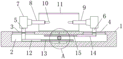
FIG. 1 is a schematic sectional view of the main view of the present invention;
FIG. 2 is an enlarged view of portion A of FIG. 1;
fig. 3 is a schematic sectional view of the top view of the present invention.
In the figure: 1. a square pillar; 2. a cavity; 3. a first through hole; 4. a second through hole; 5. a first vertical bar; 6. a second vertical bar; 7. a sleeve; 8. a first welding arm; 9. a second welding arm; 10. an electrode tip; 11. a cover cylinder; 12. a first connecting plate; 13. a first rack; 14. a second connecting plate; 15. a second rack; 16. a rotating shaft; 17. a gear; 18. fixing grooves; 19. an electric motor.
Detailed Description
The technical solutions in the embodiments of the present invention will be described clearly and completely with reference to the accompanying drawings in the embodiments of the present invention, and it is obvious that the described embodiments are only some embodiments of the present invention, not all embodiments. Based on the embodiments in the present invention, all other embodiments obtained by a person skilled in the art without creative work belong to the protection scope of the present invention.
As shown in fig. 1-3, the utility model provides a technical solution: a welding mechanism of a spot welding machine comprises a square support 1, a cavity 2 is arranged on the square support 1, a first through hole 3 and a second through hole 4 are arranged on the inner wall of the top of the cavity 2, a first vertical rod 5 is arranged in the first through hole 3 in a sliding manner, two ends of the first vertical rod 5 extend out of the first through hole 3, a second vertical rod 6 is arranged in the second through hole 4 in a sliding manner, two ends of the second vertical rod 6 extend out of the second through hole 4, sleeves 7 are fixedly arranged at the top ends of the first vertical rod 5 and the second vertical rod 6, a first welding arm 8 and a second welding arm 9 are fixedly arranged at one sides of the two sleeves 7 close to each other respectively, electrode tips 10 are fixedly arranged at one sides of the first welding arm 8 and the second welding arm 9 close to each other, a cover barrel 11 positioned between the two sleeves 7 is fixedly arranged at the top of the square support 1, one ends of the first welding arm 8 and the second welding arm 9 close to each other extend into the cover barrel, the bottom fixed mounting of first montant 5 has first connecting plate 12, one side fixed mounting of first connecting plate 12 has first rack 13, the bottom fixed mounting of second montant 6 has second connecting plate 14, one side fixed mounting of second connecting plate 14 has second rack 15, be equipped with the pivot 16 that is located between first rack 13 and the second rack 15 in the cavity 2, fixed cover is equipped with gear 17 in the pivot 16, first rack 13 and second rack 15 all mesh with gear 17 mutually.
The fixed slot 18 has been seted up on one side inner wall of cavity 2, fixed mounting has motor 19 in the fixed slot 18, the one end of pivot 16 extend to in the fixed slot 18 and with motor 19's output shaft end fixed connection, fixed mounting has first slide bar in the first through-hole 3, first montant 5 slip cap is established on first slide bar, fixed mounting has the second slide bar in the second through-hole 4, second montant 6 slip cap is established on the second slide bar, the spacing groove has all been seted up on the top inner wall of cavity 2 and the bottom inner wall, the equal fixed mounting in one side that first rack 13 and second rack 15 kept away from each other has the gag lever post, two gag lever posts are respectively slidable mounting at corresponding spacing inslot, fixed mounting has the bearing frame on one side inner wall of cavity 2, the one end rotation that motor 19 was kept away from to pivot.
When the spot welding machine is used, the square support 1 is fixedly installed on the spot welding machine, the motor 19 is a motor capable of rotating forward and backward, the spot welding machine is provided with a control switch and a power line, the motor 19, the control switch and the power line are sequentially and electrically connected to form a loop, the control switch controls the starting, the stopping and the forward and backward rotation of the motor 19, when the distance between the first welding arm 8 and the second welding arm 9 needs to be adjusted, the motor 19 is started to rotate forward, the motor 19 drives the rotating shaft 16 and the gear 17 to rotate clockwise (viewed from the main viewing direction), because the first rack 13 and the second rack 15 are both meshed with the gear 17, when the gear 17 rotates clockwise, the first rack 13 moves leftwards horizontally, the second rack 15 moves rightwards horizontally, the first rack 13 and the second rack 15 drive corresponding limiting rods to slide in corresponding limiting grooves, the first rack 13 drives the first connecting plate 12, the first vertical rod 5, the second, The left sleeve 7, the first welding arm 8 and the left electrode tip 10 horizontally move leftwards, the second rack 15 drives the second connecting plate 14, the second vertical rod 6, the right sleeve 7, the second welding arm 9 and the right electrode tip 10 horizontally move rightwards, so that the first welding arm 8 and the second welding arm 9 move towards the directions away from each other, the distance between the first welding arm 8 and the second welding arm 9 is increased, similarly, the starting motor 19 rotates reversely, the motor 19 drives the rotating shaft 16 and the gear 17 to rotate anticlockwise (viewed from the main viewing direction), the first rack 13 horizontally moves rightwards, the second rack 15 horizontally moves leftwards, the first rack 13 drives the first connecting plate 12, the first vertical rod 5, the left sleeve 7, the first welding arm 8 and the left electrode tip 10 to move horizontally rightwards, the second rack 15 drives the second connecting plate 14, the second vertical rod 6 and the right sleeve 7, The second welds arm 9 and electrode tip 10 horizontal left removal on right side for first welding arm 8 and second welding arm 9 move to the direction that is close to each other, and the interval between first welding arm 8 and the second welding arm 9 diminishes, and the interval between first welding arm 8 and the second welding arm 9 is adjusted suitable back, and stop motor 19 work can, thereby through the positive reverse work of control motor 19, can adjust the interval between first welding arm 8 and the second welding arm 9, be convenient for carry out spot welding work to the article of different sizes, improved the practicality, increased application scope, and the content that does not make detailed description in this specification all belongs to the prior art that skilled person is known simultaneously.
To sum up, in the welding mechanism of the spot welding machine, the motor 19 is started to rotate forward, the motor 19 drives the rotating shaft 16 and the gear 17 to rotate clockwise (viewed from the main viewing direction), so that the first rack 13 drives the first connecting plate 12, the first vertical rod 5, the left sleeve 7, the first welding arm 8 and the left electrode tip 10 to move horizontally leftward, the second rack 15 drives the second connecting plate 14, the second vertical rod 6, the right sleeve 7, the second welding arm 9 and the right electrode tip 10 to move horizontally rightward, the distance between the first welding arm 8 and the second welding arm 9 is increased, similarly, the motor 19 is started to rotate reversely, the motor 19 drives the rotating shaft 16 and the gear 17 to rotate counterclockwise (viewed from the main viewing direction), so that the first rack 13 drives the first connecting plate 12, the first vertical rod 5, the left sleeve 7, the first welding arm 8 and the left electrode tip 10 to move horizontally rightward, second rack 15 drives second connecting plate 14, second montant 6, sleeve pipe 7 on right side, the electrode tip 10 level left shift on second welding arm 9 and right side, and first welding arm 8 and second weld the interval between the arm 9 and diminish to through the positive reverse work of control motor 19, can adjust the interval between first welding arm 8 and the second welding arm 9, be convenient for carry out spot welding work to not unidimensional article, improved the practicality, the utility model relates to a rationally, easy operation is convenient, is convenient for adjust the interval between first welding arm 8 and the second welding arm 9, conveniently carries out spot welding work to not unidimensional article, improves welding quality, has improved the practicality, has increased application scope.
Claims (6)
1. The utility model provides a welding mechanism of spot welder, includes square pillar (1), its characterized in that: the square support (1) is provided with a cavity (2), the inner wall of the top of the cavity (2) is provided with a first through hole (3) and a second through hole (4), the first through hole (3) is internally provided with a first vertical rod (5), two ends of the first vertical rod (5) extend out of the first through hole (3), the second through hole (4) is internally provided with a second vertical rod (6), two ends of the second vertical rod (6) extend out of the second through hole (4), the top ends of the first vertical rod (5) and the second vertical rod (6) are respectively and fixedly provided with a sleeve (7), one side of the two sleeves (7) close to each other is respectively and fixedly provided with a first welding arm (8) and a second welding arm (9), one side of the first welding arm (8) and the second welding arm (9) close to each other is respectively and fixedly provided with an electrode tip (10), the top of the square support (1) is fixedly provided with a cover barrel (11) positioned between the two sleeves (7), first weld arm (8) and second and weld arm (9) one end that is close to each other and all extend to in cover section of thick bamboo (11), the bottom fixed mounting of first montant (5) has first connecting plate (12), one side fixed mounting of first connecting plate (12) has first rack (13), the bottom fixed mounting of second montant (6) has second connecting plate (14), one side fixed mounting of second connecting plate (14) has second rack (15), be equipped with pivot (16) that are located between first rack (13) and second rack (15) in cavity (2), fixed cover is equipped with gear (17) on pivot (16), first rack (13) and second rack (15) all mesh with gear (17) mutually.
2. The welding mechanism of a spot welder according to claim 1, characterized in that: a fixing groove (18) is formed in the inner wall of one side of the cavity (2), a motor (19) is fixedly mounted in the fixing groove (18), and one end of the rotating shaft (16) extends into the fixing groove (18) and is fixedly connected with an output shaft end of the motor (19).
3. The welding mechanism of a spot welder according to claim 1, characterized in that: a first sliding rod is fixedly arranged in the first through hole (3), and a first vertical rod (5) is sleeved on the first sliding rod in a sliding mode.
4. The welding mechanism of a spot welder according to claim 1, characterized in that: a second sliding rod is fixedly arranged in the second through hole (4), and a second vertical rod (6) is sleeved on the second sliding rod in a sliding manner.
5. The welding mechanism of a spot welder according to claim 1, characterized in that: spacing grooves are formed in the inner wall of the top of the cavity (2) and the inner wall of the bottom of the cavity, a spacing rod is fixedly mounted on one side, away from each other, of the first rack (13) and the second rack (15), and the two spacing rods are slidably mounted in the corresponding spacing grooves respectively.
6. The welding mechanism of a spot welder according to claim 1, characterized in that: a bearing seat is fixedly installed on the inner wall of one side of the cavity (2), and one end, far away from the motor (19), of the rotating shaft (16) is rotatably installed on the bearing seat.
Priority Applications (1)
| Application Number | Priority Date | Filing Date | Title |
|---|---|---|---|
| CN202020053296.4U CN211438539U (en) | 2020-01-11 | 2020-01-11 | Welding mechanism of spot welding machine |
Applications Claiming Priority (1)
| Application Number | Priority Date | Filing Date | Title |
|---|---|---|---|
| CN202020053296.4U CN211438539U (en) | 2020-01-11 | 2020-01-11 | Welding mechanism of spot welding machine |
Publications (1)
| Publication Number | Publication Date |
|---|---|
| CN211438539U true CN211438539U (en) | 2020-09-08 |
Family
ID=72315169
Family Applications (1)
| Application Number | Title | Priority Date | Filing Date |
|---|---|---|---|
| CN202020053296.4U Expired - Fee Related CN211438539U (en) | 2020-01-11 | 2020-01-11 | Welding mechanism of spot welding machine |
Country Status (1)
| Country | Link |
|---|---|
| CN (1) | CN211438539U (en) |
Cited By (2)
| Publication number | Priority date | Publication date | Assignee | Title |
|---|---|---|---|---|
| CN113579444A (en) * | 2021-07-05 | 2021-11-02 | 辛忠来 | Spot welding equipment for aluminum alloy workpiece |
| CN114682893A (en) * | 2022-04-22 | 2022-07-01 | 宿迁启辉照明电器有限公司 | Spot welding machine capable of adjusting spot welding angle for halogen lamp production and adjusting method |
-
2020
- 2020-01-11 CN CN202020053296.4U patent/CN211438539U/en not_active Expired - Fee Related
Cited By (2)
| Publication number | Priority date | Publication date | Assignee | Title |
|---|---|---|---|---|
| CN113579444A (en) * | 2021-07-05 | 2021-11-02 | 辛忠来 | Spot welding equipment for aluminum alloy workpiece |
| CN114682893A (en) * | 2022-04-22 | 2022-07-01 | 宿迁启辉照明电器有限公司 | Spot welding machine capable of adjusting spot welding angle for halogen lamp production and adjusting method |
Similar Documents
| Publication | Publication Date | Title |
|---|---|---|
| CN211438539U (en) | Welding mechanism of spot welding machine | |
| CN210413289U (en) | Platform upset welding frock | |
| CN211276937U (en) | Butt welder for building construction | |
| CN216706263U (en) | Butt welder is used in welding wire production | |
| CN210188797U (en) | Spot welding machine capable of moving in all directions | |
| CN215698741U (en) | Welding wire increases silk equipment suitable for automatic submerged arc welding machine | |
| CN216097176U (en) | Welding device for steel structure | |
| CN215089969U (en) | Pipe bending device for machining electric heating pipe | |
| CN215034359U (en) | Argon arc welding transmission control device for heater | |
| CN210001889U (en) | clamping device for heat treatment of metal materials | |
| CN211638650U (en) | Spot welding machine with limiting function | |
| CN212822608U (en) | Electroslag fusion consumable electrode center frame | |
| CN209998607U (en) | straight line welding auxiliary device | |
| CN217799531U (en) | Multipoint spot welding machine for producing automobile silencer | |
| CN214185704U (en) | Pressure test spot welder | |
| CN111730237A (en) | Welding device for inverter production and processing | |
| CN219986517U (en) | Gantry type laser arc composite welding equipment | |
| CN211413992U (en) | Welding tool for longitudinal and circumferential weld joints of barrel | |
| CN217412772U (en) | Direct current welding machine convenient for adjusting welding point | |
| CN211052814U (en) | Butt-joint welder is used in bicycle front fork production | |
| CN220217069U (en) | Spot welder with accurate positioning | |
| CN209565702U (en) | A kind of resistance welder | |
| CN212918032U (en) | Seam welder with guide wheels distributed up and down | |
| CN216028718U (en) | Vertical spot welder is used in spare part processing | |
| CN214291343U (en) | Single-wheel seam welding special machine |
Legal Events
| Date | Code | Title | Description |
|---|---|---|---|
| GR01 | Patent grant | ||
| GR01 | Patent grant | ||
| CF01 | Termination of patent right due to non-payment of annual fee |
Granted publication date: 20200908 |
|
| CF01 | Termination of patent right due to non-payment of annual fee |