CN211428761U - Electric coaster for overhauling obstacle crossing of extra-high voltage direct current grounding electrode circuit - Google Patents
Electric coaster for overhauling obstacle crossing of extra-high voltage direct current grounding electrode circuit Download PDFInfo
- Publication number
- CN211428761U CN211428761U CN201921952969.3U CN201921952969U CN211428761U CN 211428761 U CN211428761 U CN 211428761U CN 201921952969 U CN201921952969 U CN 201921952969U CN 211428761 U CN211428761 U CN 211428761U
- Authority
- CN
- China
- Prior art keywords
- obstacle crossing
- control cylinder
- extra
- electric control
- direct current
- Prior art date
- Legal status (The legal status is an assumption and is not a legal conclusion. Google has not performed a legal analysis and makes no representation as to the accuracy of the status listed.)
- Active
Links
Images

Abstract
The utility model discloses an extra-high voltage direct current grounding electrode line maintenance obstacle crossing electric coaster, which comprises a main body frame and an obstacle crossing device, wherein a seat and a power supply are arranged in the main body frame; the obstacle crossing device comprises two main rods, two driving wheels and four driven wheels, wherein the main rods are connected to two sides of the main body frame, the top ends of the main rods are in U-shaped structures, and the driving wheels are arranged in grooves of the U-shaped structures; the central shafts of the two driving wheels are respectively connected with two output ends of the motor with double output shafts, and a brake device is arranged below the driving wheels; a driven wheel is arranged on each of the front side and the rear side of each driving wheel, the central shaft of each driven wheel is connected with a first electric control cylinder, and the driving wheel and the driven wheel on the same side are connected through a support rod; the main body frame is provided with a central control platform for controlling the extension and retraction of the first electric control cylinder. The utility model provides an overhaul driving accords with laborsaving light and handy, safe and reliable's requirement, can easily stride across obstacles such as conductor spacer, stockbridge damper on the transmission line, and the operation task can be accomplished more fast, safely, high-efficiently to the operating personnel.
Description
Technical Field
The utility model relates to an extra-high voltage direct current earthing pole circuit overhauls electronic driving of obstacle belongs to live working technical field.
Background
At present, equipotential personnel are mostly used for wiring or overhauling a flying vehicle when live-line work such as line patrol, spacer replacement, wire repair and the like is carried out in the middle of span in China.
The existing overhaul flying car can be divided into a single-line flying car and a double-line flying car, and can be divided from the aspect of power: manual, electric, chain-driven, and shaft-driven. The manual type galloping is that an operator holds the power transmission line by two hands and moves forwards and backwards, so that the operator is very labourious when climbing upwards facing the power transmission line; the electric type is that the electric power is used as power to move back and forth, the structure is relatively complex, and the operation is not easy; the chain transmission type is similar to the principle of a bicycle, and has the defect that the chain is easy to fall off, so that the power is lost in the air; the shaft transmission type is similar to gear transmission, the structure operation is stable, but the galloping car cannot span when meeting obstacles such as a spacer, a shockproof hammer, a suspension clamp and the like on a power transmission line in the process of running, and certain limitation is realized.
SUMMERY OF THE UTILITY MODEL
The purpose is as follows: inconvenience in the conductor spacer use is strideed across to current maintenance driving, the utility model provides an extra-high voltage direct current earthing pole circuit overhauls electronic driving of obstacle adopts direct current low-speed brushless motor drive device to walk, adopts the lift of automatically controlled cylinder drive from the driving wheel, can easily stride across obstacles such as conductor spacer and stockbridge damper.
The technical scheme is as follows: in order to solve the technical problem, the utility model discloses a technical scheme does:
an electric obstacle crossing coaster for extra-high voltage direct current grounding electrode line maintenance comprises a main body frame and an obstacle crossing device, wherein a seat and a power supply are arranged in the main body frame;
the obstacle crossing device comprises two main rods, two driving wheels and two driven wheels, the two main rods are respectively connected to two opposite sides of the main body framework, the top ends of the main rods are of U-shaped structures, the driving wheels are arranged in grooves of the U-shaped structures, and central shafts of the two driving wheels are respectively connected with two output ends of a motor with double output shafts; an inner clamping groove and an outer clamping groove are formed in the outer edge of the center of the driving wheel from inside to outside; one of the two main rods is provided with a brake device;
the four driven wheels are arranged, one driven wheel is arranged on each of the front side and the rear side of the driving wheel along the same power transmission line, and a central shaft of each driven wheel is connected with the first electric control cylinder; the driven wheel and the driving wheel which are positioned on the same side are connected through a supporting rod, and the supporting rod is hinged with the central shaft of the driving wheel and the central shaft of the driven wheel;
a central control platform is arranged on the main body frame and connected with the first electric control cylinder;
the power supply is electrically connected with the double-output-shaft motor and the first electric control cylinder.
Further, the diameter of the cross section of the inner clamping groove is slightly larger than that of the cross section of the power transmission line, and the diameter of the cross section of the outer clamping groove is slightly larger than that of the spacer.
Furthermore, a limiting nut is arranged at the joint of the central shaft of the driving wheel and the output end of the motor with double output shafts.
Furthermore, the surface of the U-shaped structure at the top of the main rod is fixed with a lock catch, and the two lock catches are connected through a safety rope.
Further, the central shaft of the driven wheel is connected with the main body frame through a traction rope.
Furthermore, a platform is fixed on the main rod, one end of the first electric control cylinder is connected with a central shaft of the driven wheel, and the other end of the first electric control cylinder is connected with the platform.
Furthermore, the brake device comprises a second electric control cylinder and a brake wheel, the second electric control cylinder is fixed on one side of the main rod, the output end of the second electric control cylinder is upwards connected with the brake wheel, and the brake wheel is positioned below the driving wheel; the second electric control cylinder is electrically connected with a power supply.
Further, the power supply is a lithium battery power supply.
Has the advantages that: the utility model provides an extra-high voltage direct current earth electrode circuit overhauls obstacle-surmounting electric coaster, can stride across obstacles such as conductor spacer on the circuit, adopts high energy lithium cell as the power, and operating time is long, and obstacle-surmounting efficiency is high, and simple to operate, safe firm; the line inspection and maintenance efficiency of the extra-high voltage line is greatly improved, the labor intensity of operators is reduced, and the safety of the operators is guaranteed.
Drawings
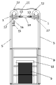
Fig. 1 is a schematic front structural view of the present invention;
fig. 2 is a schematic side view of the present invention;
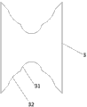
fig. 3 is a schematic structural view of the driving wheel.
Detailed Description
The present invention will be further described with reference to the accompanying drawings.
As shown in fig. 1 and 2, an electric coaster for extra-high voltage direct current grounding electrode line maintenance and obstacle crossing comprises a main body frame 8 and an obstacle crossing device.
The main body frame 8 is formed by welding aluminum alloy pipes, so that the whole equipment is lighter in weight, and a seat 10 and a power supply 9 are arranged in the frame; the power supply 9 is a high-energy lithium battery.
The obstacle crossing device comprises two main rods 5, two driving wheels 1 and four driven wheels 3, wherein the two main rods 5 are respectively connected to two opposite sides of a main body frame 1, the top ends of the main rods 5 are of U-shaped structures, the lock catches 12 are fixed on the upper surfaces of the U-shaped structures, and the two lock catches 12 are connected through safety ropes 11.
The driving wheels 1 are arranged in the grooves of the U-shaped structures, central shafts of the two driving wheels 1 are respectively connected with two output ends of a motor 14 with double output shafts, and a limiting nut 13 is arranged at the joint of the central shaft of the driving wheel 1 and the output ends of the motor 14 with the double output shafts;
an inner clamping groove 31 and an outer clamping groove 32 are formed in the outer edge of the center of the driving wheel 1 from inside to outside, the diameter of the cross section of the inner clamping groove 31 is slightly larger than that of the power transmission line 17, and the diameter of the cross section of the outer clamping groove 32 is slightly larger than that of the spacer, as shown in fig. 3. The slightly larger concept is clearly understood by those skilled in the art, that is, the inner card slot 31 can be clamped outside the power transmission line 17, and the driving wheel 1 can move along the power transmission line 17 without being separated from the power transmission line 17; when encountering the spacing rod, the external clamping groove 32 can be clamped outside the spacing rod, and the driving wheel 1 can stride over the spacing rod under the driving of the motor.
Along the same power transmission line, the front side and the rear side of a driving wheel 1 are respectively provided with a driven wheel 3, and the central shaft of the driven wheel 3 is connected with a first electric control cylinder 6; the driven wheel 3 and the driving wheel 1 which are positioned on the same side are connected through a supporting rod 2, and the supporting rod 2 is hinged with the central shaft of the driving wheel 1 and the central shaft of the driven wheel 3; the driven wheel 3 can be driven to rise or fall by the first electric control cylinder 6.
Further, a platform 4 is fixed on the main rod 1, one end of the first electric control cylinder 6 is fixedly connected with a central shaft of the driven wheel 3 through a bolt, and the other end of the first electric control cylinder is connected with the platform 4 in a welding mode.
The central shaft of the driven wheel 3 is connected with the main body frame 8 through a traction rope 18, so that the stability of the whole galloping device is improved.
One of the two main rods 5 is provided with a brake device, the brake device comprises a second electric control cylinder 15 and a brake wheel 16, the second electric control cylinder 15 is fixed on one side of the main rods 5, the output end of the second electric control cylinder 15 is upwards connected with the brake wheel 16, and the brake wheel 16 is positioned below the driving wheel 1. When the brake is needed, the second electric control cylinder 15 is started, the brake wheel 16 is lifted upwards, the brake wheel 16 tightly holds the power transmission line 17, and the maintenance coaster stops moving forwards.
The first electric control cylinder 6, the double output shaft motor 14 and the second electric control cylinder 15 are electrically connected with the power supply 9.
A central control platform 7 is arranged on the main body frame 8, the central control platform 7 is connected with the first electric control cylinder 6, and a lifting button and a descending button are arranged on the central control platform 7; the two central control platforms 7 are respectively used for controlling the lifting of the front driven wheel and the lifting of the rear driven wheel. The central control platform 7 is electrically connected with a lithium battery power supply.
The utility model provides a pair of special high voltage direct current earthing pole circuit overhauls the process of strideing across the conductor spacer in the electronic driving work as follows:
when encountering a spacer, an operator presses a lifting button on a central control platform 7 for controlling the front driven wheel, a first electric control cylinder 6 on the front side lifts the front driven wheel 3, and the front driven wheel 3 passes over the spacer; the front driven wheel 3 goes over the spacer and then presses down the descending button, the first electric control cylinder 6 on the front side drives the front driven wheel 3 to descend, and the front driven wheel 3 is attached to the power transmission line 17 to continue to advance. The central channel of the driving wheel 1 is a transitional combination of an inner clamping groove and an outer clamping groove, the shape and the size of the outer clamping groove are close to the obstacle, namely the shape design of the spacer, and the motor 14 with double output shafts provides sufficient power to enable the driving wheel 1 to easily cross over the spacer. Then, an operator presses a lifting button on a central control platform 7 for controlling the rear driven wheel, a first electric control cylinder 6 on the rear side lifts the rear driven wheel 3, and the rear driven wheel 3 passes over the spacing rod; the rear driven wheel 3 crosses the spacer and then presses down the descending button, the first electric control cylinder 6 at the rear drives the rear driven wheel 3 to descend, and the rear driven wheel 3 is attached to the power transmission line 17 and continues to advance.
The above description is only a preferred embodiment of the present invention, and it should be noted that: for those skilled in the art, without departing from the principle of the present invention, several improvements and modifications can be made, and these improvements and modifications should also be considered as the protection scope of the present invention.
Claims (8)
1. The utility model provides an extra-high voltage direct current earthing pole circuit overhauls electronic driving of obstacle which characterized in that: the obstacle crossing device comprises a main body frame and an obstacle crossing device, wherein a seat and a power supply are arranged in the main body frame;
the obstacle crossing device comprises two main rods, two driving wheels and two driven wheels, the two main rods are respectively connected to two opposite sides of the main body framework, the top ends of the main rods are of U-shaped structures, the driving wheels are arranged in grooves of the U-shaped structures, and central shafts of the two driving wheels are respectively connected with two output ends of a motor with double output shafts; an inner clamping groove and an outer clamping groove are formed in the outer edge of the center of the driving wheel from inside to outside; one of the two main rods is provided with a brake device;
the four driven wheels are arranged, one driven wheel is arranged on each of the front side and the rear side of the driving wheel along the same power transmission line, and a central shaft of each driven wheel is connected with the first electric control cylinder; the driven wheel and the driving wheel which are positioned on the same side are connected through a supporting rod, and the supporting rod is hinged with the central shaft of the driving wheel and the central shaft of the driven wheel;
a central control platform is arranged on the main body frame and connected with the first electric control cylinder;
the power supply is electrically connected with the double-output-shaft motor and the first electric control cylinder.
2. The electric coaster of extra-high voltage direct current earthing pole line maintenance obstacle crossing of claim 1, characterized in that: the diameter of the cross section of the inner clamping groove is slightly larger than that of the cross section of the power transmission line, and the diameter of the cross section of the outer clamping groove is slightly larger than that of the spacer.
3. The electric coaster of extra-high voltage direct current earthing pole line maintenance obstacle crossing of claim 1, characterized in that: and a limiting nut is arranged at the joint of the central shaft of the driving wheel and the output end of the motor with double output shafts.
4. The electric coaster of extra-high voltage direct current earthing pole line maintenance obstacle crossing of claim 1, characterized in that: the upper surface of the U-shaped structure at the top of the main rod is fixed with the lock catch, and the two lock catches are connected through the safety rope.
5. The electric coaster of extra-high voltage direct current earthing pole line maintenance obstacle crossing of claim 1, characterized in that: the central shaft of the driven wheel is connected with the main body frame through a traction rope.
6. The electric coaster of extra-high voltage direct current earthing pole line maintenance obstacle crossing of claim 1, characterized in that: the main rod is fixed with a platform, one end of the first electric control cylinder is connected with a central shaft of the driven wheel, and the other end of the first electric control cylinder is connected with the platform.
7. The electric coaster of extra-high voltage direct current earthing pole line maintenance obstacle crossing of claim 1, characterized in that: the brake device comprises a second electric control cylinder and a brake wheel, the second electric control cylinder is fixed on one side of the main rod, the output end of the second electric control cylinder is upwards connected with the brake wheel, and the brake wheel is positioned below the driving wheel; the second electric control cylinder is electrically connected with a power supply.
8. The electric coaster of extra-high voltage direct current earthing pole line maintenance obstacle crossing of claim 1 or 7, characterized in that: the power supply is a lithium battery power supply.
Priority Applications (1)
| Application Number | Priority Date | Filing Date | Title |
|---|---|---|---|
| CN201921952969.3U CN211428761U (en) | 2019-11-13 | 2019-11-13 | Electric coaster for overhauling obstacle crossing of extra-high voltage direct current grounding electrode circuit |
Applications Claiming Priority (1)
| Application Number | Priority Date | Filing Date | Title |
|---|---|---|---|
| CN201921952969.3U CN211428761U (en) | 2019-11-13 | 2019-11-13 | Electric coaster for overhauling obstacle crossing of extra-high voltage direct current grounding electrode circuit |
Publications (1)
| Publication Number | Publication Date |
|---|---|
| CN211428761U true CN211428761U (en) | 2020-09-04 |
Family
ID=72283842
Family Applications (1)
| Application Number | Title | Priority Date | Filing Date |
|---|---|---|---|
| CN201921952969.3U Active CN211428761U (en) | 2019-11-13 | 2019-11-13 | Electric coaster for overhauling obstacle crossing of extra-high voltage direct current grounding electrode circuit |
Country Status (1)
| Country | Link |
|---|---|
| CN (1) | CN211428761U (en) |
-
2019
- 2019-11-13 CN CN201921952969.3U patent/CN211428761U/en active Active
Similar Documents
| Publication | Publication Date | Title |
|---|---|---|
| CN101574983B (en) | Lead obstacle-crossing robot walking device | |
| CN211858329U (en) | Swift power transformer installation device | |
| CN102231490B (en) | Manned traveling locomotive for high-voltage transmission line | |
| EP1925492A3 (en) | Portal fork-lift truck with a turbine drive low in emissions and maintenance | |
| CN201648963U (en) | Continuous mobile cable robot creeping device | |
| CN106166372B (en) | Electric pole inspection platform voluntarily climbing device | |
| CN105281250A (en) | Electric spacer cart for maintenance operations of 4-bundle conductor of 500kV power transmission line | |
| CN110061447A (en) | A kind of power transmission lines overhauling is with can obstacle detouring electric aerodyne | |
| CN205081394U (en) | A electric ranaway for 500kV transmission line four -bundled conductor overhauls operation | |
| CN211428761U (en) | Electric coaster for overhauling obstacle crossing of extra-high voltage direct current grounding electrode circuit | |
| CN111313314A (en) | Electric coaster for overhauling obstacle crossing of extra-high voltage direct current grounding electrode circuit | |
| CN216332385U (en) | Cross locking type robot for climbing telegraph pole | |
| CN113879418A (en) | Cross locking type robot for climbing telegraph pole | |
| CN205999791U (en) | A kind of prestressed stretch-draw combination type tensioning stand | |
| CN210246126U (en) | Obstacle-crossing wiring aerodyne | |
| CN206644929U (en) | Novel elevating arm tricycle | |
| CN201283750Y (en) | Wheel dismantling vehicle | |
| CN202542780U (en) | Motor-lifting trolley | |
| CN219257437U (en) | Electrical installation transfer device | |
| CN218620042U (en) | Movable prefabricated wall body tractor | |
| CN103662700A (en) | Self-propelled trolley with engine assembled in combined manner | |
| CN207719725U (en) | A kind of tool for clearing up foreign matter on transmission & distribution electric lead | |
| CN202059101U (en) | Self-propelled wire outlet overhead trolley for transmission line overhaul | |
| CN210142871U (en) | Transmission line insulator chain overhauls transmission coaster | |
| CN217350647U (en) | Electric power installation and maintenance platform |
Legal Events
| Date | Code | Title | Description |
|---|---|---|---|
| GR01 | Patent grant | ||
| GR01 | Patent grant |