CN211414524U - Five supporting legss for digit control machine tool with shockproof function - Google Patents
Five supporting legss for digit control machine tool with shockproof function Download PDFInfo
- Publication number
- CN211414524U CN211414524U CN201922411442.6U CN201922411442U CN211414524U CN 211414524 U CN211414524 U CN 211414524U CN 201922411442 U CN201922411442 U CN 201922411442U CN 211414524 U CN211414524 U CN 211414524U
- Authority
- CN
- China
- Prior art keywords
- machine tool
- rod
- control machine
- worm
- shockproof function
- Prior art date
- Legal status (The legal status is an assumption and is not a legal conclusion. Google has not performed a legal analysis and makes no representation as to the accuracy of the status listed.)
- Active
Links
Images


Abstract
The utility model belongs to the technical field of the supporting legs, especially, for a five-axis supporting legs for digit control machine tool with shockproof function, including touching landmass and slide bar, touch the top of landmass and install the threaded rod, and the avris of threaded rod is provided with worm gear spare to worm gear spare's the outside is installed worm member, worm member's end department has seted up square groove, worm gear spare's top is provided with the fagging, and goes up the upper surface of fagging and has seted up the guide way, the internally mounted of guide way has the guide bar, and the top of guide bar is provided with the pretension board, first spring is installed to the below of pretension board, the below of going up the fagging is provided with down the fagging, and the slide cartridge is installed to the outer wall of lower fagging. This five-axis supporting legs for digit control machine tool with shockproof function possesses good shockproof function and avoids the lathe during operation vibrations to cause the damage to workshop ground and operating personnel, is convenient for supplementary lathe removal and has improved the efficiency of lathe position adjustment work in the workshop.
Description
Technical Field
The utility model relates to a supporting legs technical field specifically is a five-axis supporting legs for digit control machine tool with shockproof function.
Background
In the modern manufacturing industry, numerical control machine tools are mostly adopted to machine and manufacture metal parts, particularly in the field of precision manufacturing, the application of a five-axis numerical control machine tool is very wide, the five-axis numerical control machine tool is a machine tool which has high technological content and high precision and is specially used for machining complex curved surfaces, and in the five-axis numerical control machine tool, the application and research and development of supporting legs are developing at a high speed along with the five-axis numerical control machine tool.
Most shockproof functions of common supporting legs for five-axis numerical control machine tools in the market are poor, severe vibration generated in the machining process of the five-axis numerical control machine tools is caused to damage the workshop ground to a certain extent, the physical health of operators is harmed permanently, on the other hand, the existing supporting legs for five-axis numerical control machine tools are not convenient to assist machine tool movement mostly, so that a factory needs to use other equipment to perform auxiliary work when adjusting the position of the machine tool in the workshop, the working cost is improved, the difficulty of adjustment work is increased, the market needs a good shockproof function, the novel supporting legs for five-axis numerical control machine tools convenient to assist machine tool movement, the innovative design is urgently needed to be performed on the basis of the original supporting legs for five-axis numerical control machine tools, and the supporting legs for five-axis numerical control machine tools with.
SUMMERY OF THE UTILITY MODEL
An object of the utility model is to provide a five-axis numerically-controlled machine tool with shockproof function is with supporting legs to provide current five-axis numerically-controlled machine tool with shockproof function in solving above-mentioned background art and use the supporting legs, like product does not possess good shockproof function, is not convenient for assist the problem that the lathe removed.
In order to achieve the above object, the utility model provides a following technical scheme: a supporting leg with a shock-proof function for a five-axis numerical control machine tool comprises a ground contacting block and a sliding rod, wherein a threaded rod is arranged above the ground contacting block, a worm wheel piece is arranged on the side of the threaded rod, a worm rod piece is arranged on the outer side of the worm wheel piece, a square groove is arranged at the end of the worm rod piece, an upper supporting plate is arranged above the worm wheel piece, and the upper surface of the upper supporting plate is provided with a guide groove, a guide rod is arranged in the guide groove, a pretightening plate is arranged above the guide rod, a first spring is arranged below the pre-tightening plate, a lower supporting plate is arranged below the upper supporting plate, a sliding cylinder is arranged on the outer wall of the lower supporting plate, and the inside of a sliding cylinder is provided with a second spring, the sliding rod is arranged below the second spring, the end of the sliding rod is connected with a connecting frame, and a roller is arranged below the connecting frame.
Preferably, a transmission structure is arranged between the worm rod piece and the worm gear piece, the inner wall of the worm gear piece is arranged in a threaded manner, and the worm gear piece is in threaded connection with the threaded rod.
Preferably, a sliding structure is formed between the guide rod and the upper supporting plate through the guide groove, and the outer wall of the guide rod is tightly attached to the surface of the guide groove.
Preferably, a lifting structure is formed between the pre-tightening plate and the upper supporting plate through first springs, and the first springs are distributed above the upper supporting plate at equal intervals along the horizontal direction.
Preferably, a lifting mounting structure is formed between the sliding cylinder and the sliding rod through a second spring, and the sliding cylinder is symmetrically provided with 4 sliding cylinders around the central axis of the threaded rod.
Preferably, a rotating structure is formed between the connecting frame and the sliding cylinder through the sliding rods, and the connecting frame is symmetrically provided with 4 connecting rods around the central axis of the threaded rod.
Compared with the prior art, the beneficial effects of the utility model are that: the support leg with the shockproof function for the five-axis numerical control machine tool has a good shockproof function, avoids damage to workshop ground and operators caused by shock when the machine tool works, is convenient for assisting the machine tool to move, and improves the efficiency of machine tool position adjustment work in a workshop;
1. the support leg with the shockproof function for the five-axis numerical control machine tool rotates a worm rod piece through a square groove, so that worm and gear transmission is carried out between the worm rod piece and the square groove, the worm gear piece rotates by taking a threaded rod as an axis, simultaneously, threads on the inner wall of the worm gear piece are mutually screwed with threads of the threaded rod, so that the threaded rod moves downwards relative to the worm gear piece, the threaded rod pushes a ground contact block downwards to contact the ground to realize a support function, simultaneously, as the threaded rod descends relatively, the thread part at the top end of the threaded rod is completely screwed and separated from the bottom of a machine tool, the bottom of the machine tool presses the upper surface of a pre-tightening plate of the support leg, at the moment, the part of the threaded rod, which is higher than the upper surface of the pre-tightening plate, is unthreaded, the threaded rod is fixedly connected with the bottom of the machine tool, at the moment, when the machine tool generates shock during operation, the shock is transmitted, the shockproof function is realized, the damage of the vibration to the workshop ground and operators is avoided when the machine tool works, meanwhile, the guide function is provided by the sliding of the guide rod in the guide groove when the pre-tightening plate moves, the position of the pre-tightening plate is prevented from being deviated, and the pre-tightening plate is more stable in vibration and shock absorption;
2. the supporting leg with the shockproof function for the five-axis numerical control machine tool reversely rotates a worm rod piece through a square groove, a threaded rod is lifted upwards after transmission, threads at the top of the threaded rod are screwed with the bottom of a machine tool to be connected in a threaded manner, the machine tool and the supporting leg are fixed with each other due to the mutual fixation between the machine tool and the threaded rod, so that the machine tool and a pre-tightening plate are fixed relatively, the situation that the machine tool is separated from the supporting leg due to the relative movement between the machine tool and the pre-tightening plate when the position of the machine tool is moved is avoided, a movable contact block is driven to ascend to be separated from the ground when the threaded rod moves upwards, the supporting leg is contacted with the ground through a roller, the supporting leg can move in all directions in a horizontal plane through the rolling function of the roller and a rotating structure between a connecting frame and a second spring, and, and through the arrangement of a telescopic lifting structure formed by a second spring between the sliding rod and the sliding cylinder, the supporting leg has the functions of shock absorption and buffering when supporting the five-axis numerical control machine tool to move.
Drawings
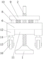
Fig. 1 is a schematic view of the overall front view cross-sectional structure of the present invention;
FIG. 2 is a schematic view of the overall structure of the present invention;
fig. 3 is a schematic overall side view of the present invention.
In the figure: 1. contacting the land mass; 2. a threaded rod; 3. a worm gear; 4. a worm member; 5. a square groove; 6. an upper supporting plate; 7. a guide groove; 8. a guide bar; 9. pre-tightening the plate; 10. a first spring; 11. a lower supporting plate; 12. a sliding cylinder; 13. a second spring; 14. a slide bar; 15. a connecting frame; 16. and a roller.
Detailed Description
The technical solutions in the embodiments of the present invention will be described clearly and completely with reference to the accompanying drawings in the embodiments of the present invention, and it is obvious that the described embodiments are only some embodiments of the present invention, not all embodiments. Based on the embodiments in the present invention, all other embodiments obtained by a person skilled in the art without creative work belong to the protection scope of the present invention.
Referring to fig. 1-3, the present invention provides a technical solution: a supporting leg with a shock-proof function for a five-axis numerical control machine tool comprises a ground contacting block 1, a threaded rod 2, a worm gear piece 3, a worm piece 4, a square groove 5, an upper supporting plate 6, a guide groove 7, a guide rod 8, a pre-tightening plate 9, a first spring 10, a lower supporting plate 11, a sliding cylinder 12, a second spring 13, a sliding rod 14, a connecting frame 15 and a roller 16, wherein the threaded rod 2 is installed above the ground contacting block 1, the worm gear piece 3 is arranged on the lateral side of the threaded rod 2, the worm rod piece 4 is installed on the outer side of the worm gear piece 3, the square groove 5 is arranged at the end of the worm piece 4, the upper supporting plate 6 is arranged above the worm gear piece 3, the guide groove 7 is arranged on the upper surface of the upper supporting plate 6, the guide rod 8 is installed inside the guide groove 7, the pre-tightening plate 9 is arranged above the guide rod 8, the first spring 10 is installed below the pre-tightening plate 9, the lower supporting plate, a sliding cylinder 12 is installed on the outer wall of the lower supporting plate 11, a second spring 13 is arranged inside the sliding cylinder 12, a sliding rod 14 is installed below the second spring 13, the end of the sliding rod 14 is connected with a connecting frame 15, and a roller 16 is arranged below the connecting frame 15;
a transmission structure is arranged between the worm rod piece 4 and the worm wheel piece 3, the inner wall of the worm wheel piece 3 is arranged in a threaded manner, the worm wheel piece 3 is in threaded connection with the threaded rod 2, the worm rod piece 4 can be rotated through the square groove 5 through the arrangement of the transmission structure, the worm wheel piece 3 is rotated through transmission, and then the threads on the inner wall of the worm wheel piece 3 are screwed with the threads on the threaded rod 2, so that the threaded rod 2 can realize lifting movement;
a sliding structure is formed between the guide rod 8 and the upper supporting plate 6 through the guide groove 7, the outer wall of the guide rod 8 is tightly attached to the surface of the guide groove 7, a guide function is provided through the sliding of the guide rod 8 in the guide groove 7, the position of the pre-tightening plate 9 is prevented from being deviated, and the pre-tightening plate 9 is more stable in vibration and shock absorption;
a lifting structure is formed between the pre-tightening plate 9 and the upper supporting plate 6 through the first springs 10, the first springs 10 are distributed above the upper supporting plate 6 at equal intervals along the horizontal direction, and when the pre-tightening plate 9 and the upper supporting plate 6 generate relative motion, the first springs 10 perform telescopic automatic lifting motion, so that the functions of buffering and absorbing shock are realized, and the damage to the workshop ground and operators caused by the shock during the work of a machine tool is avoided;
a lifting installation structure is formed between the sliding cylinder 12 and the sliding rod 14 through a second spring 13, 4 sliding cylinders 12 are symmetrically arranged about the central axis of the threaded rod 2, and the support leg has the functions of shock absorption and buffering when supporting the five-axis numerical control machine tool to move through the arrangement of a telescopic lifting structure formed by the second spring 13 between the sliding rod 14 and the sliding cylinder 12;
a rotating structure is formed between the connecting frame 15 and the sliding cylinder 12 through the sliding rod 14, 4 connecting frames 15 are symmetrically arranged about the central axis of the threaded rod 2, and the supporting legs can move in all directions in the horizontal plane through the rotating structure between the connecting frame 15 and the second spring 13 and the rotating function between the idler wheel 16 and the connecting frame 15, so that the supporting legs support the machine tool to realize the moving function.
The working principle is as follows: when the support leg for the five-axis numerical control machine tool with the shockproof function is used, as shown in the figure 1-3, the support leg for the five-axis numerical control machine tool rotates the worm rod piece 4 through the square groove 5, so that worm gear transmission is carried out between the worm piece 4 and the square groove 5, further the worm wheel piece 3 rotates by taking the threaded rod 2 as an axis, simultaneously the threads on the inner wall of the worm wheel piece 3 are mutually screwed with the threads of the threaded rod 2, so that the threaded rod 2 moves downwards relative to the worm wheel piece 3, then the threaded rod 2 pushes the movable grounding block 1 downwards to contact the ground to realize the support function, simultaneously, as the threaded rod 2 descends relatively, the threaded part on the top end of the threaded rod 2 is completely screwed and separated from the bottom of the machine tool, the bottom of the machine tool tightly presses the upper surface of the pre-tightening plate 9 of the support leg, at the moment, the part, at the moment, when the machine tool generates vibration during operation, the vibration is transmitted to the pre-tightening plate 9 from the bottom of the machine tool to enable the pre-tightening plate to vibrate, then the pre-tightening plate 9 and the upper supporting plate 6 are subjected to telescopic automatic lifting motion buffering and vibration absorption through the first spring 10, a vibration-proof function is realized, damage to the workshop ground and operating personnel caused by vibration during the operation of the machine tool is avoided, meanwhile, a guide function is provided by the sliding of the guide rod 8 in the guide groove 7 during the movement of the pre-tightening plate 9, the position of the pre-tightening plate 9 is prevented from being deviated, and the vibration absorption of the pre-;
according to the drawings of 1-3, the supporting leg for the five-axis numerical control machine tool reversely rotates a worm member 4 through a square groove 5, a threaded rod 2 is lifted upwards after transmission, simultaneously, the top thread of the threaded rod 2 is screwed with the bottom of a machine tool for threaded connection, and the machine tool is fixed with the threaded rod 2, so that the machine tool is fixed with a pre-tightening plate 9, the situation that the machine tool is separated from the supporting leg due to relative movement between the machine tool and the pre-tightening plate 9 when the machine tool is moved is avoided, a movable grounding block 1 is driven to lift to separate from the ground when the threaded rod 2 moves upwards, the supporting leg is contacted with the ground through a roller 16, and the supporting leg can move in all directions in a horizontal plane through the rolling function of the roller 16 and the rotating structure between a connecting frame 15 and a second spring 13, furthermore, the support leg supports the machine tool to realize a moving function, and the support leg supports the five-axis numerical control machine tool to have a shock absorption and buffering function when moving through the arrangement of a telescopic lifting structure formed by the second spring 13 between the sliding rod 14 and the sliding cylinder 12.
Although embodiments of the present invention have been shown and described, it will be appreciated by those skilled in the art that changes, modifications, substitutions and alterations can be made in these embodiments without departing from the principles and spirit of the invention, the scope of which is defined in the appended claims and their equivalents.
Claims (6)
1. The utility model provides a five digit control machine tool with shockproof function are with supporting legs, is including touching landmass (1) and slide bar (14), its characterized in that: a threaded rod (2) is installed above the ground contact block (1), a worm gear piece (3) is arranged on the side of the threaded rod (2), a worm rod piece (4) is installed on the outer side of the worm gear piece (3), a square groove (5) is formed in the end of the worm rod piece (4), an upper supporting plate (6) is arranged above the worm gear piece (3), a guide groove (7) is formed in the upper surface of the upper supporting plate (6), a guide rod (8) is installed inside the guide groove (7), a pre-tightening plate (9) is arranged above the guide rod (8), a first spring (10) is installed below the pre-tightening plate (9), a lower supporting plate (11) is arranged below the upper supporting plate (6), a sliding cylinder (12) is installed on the outer wall of the lower supporting plate (11), a second spring (13) is arranged inside the sliding cylinder (12), and a sliding rod (14) is installed below the second spring (13), and the end of the sliding rod (14) is connected with a connecting frame (15), and a roller (16) is arranged below the connecting frame (15).
2. The supporting leg with the shockproof function for the five-axis numerical control machine tool according to claim 1, is characterized in that: the worm rod piece (4) and the worm wheel piece (3) are in a transmission structure, the inner wall of the worm wheel piece (3) is arranged in a threaded manner, and the worm wheel piece (3) is in threaded connection with the threaded rod (2).
3. The supporting leg with the shockproof function for the five-axis numerical control machine tool according to claim 1, is characterized in that: a sliding structure is formed between the guide rod (8) and the upper supporting plate (6) through the guide groove (7), and the outer wall of the guide rod (8) is tightly attached to the surface of the guide groove (7).
4. The supporting leg with the shockproof function for the five-axis numerical control machine tool according to claim 1, is characterized in that: the lifting structure is formed between the pre-tightening plate (9) and the upper supporting plate (6) through the first springs (10), and the first springs (10) are distributed above the upper supporting plate (6) at equal intervals along the horizontal direction.
5. The supporting leg with the shockproof function for the five-axis numerical control machine tool according to claim 1, is characterized in that: a lifting installation structure is formed between the sliding cylinder (12) and the sliding rod (14) through a second spring (13), and 4 sliding cylinders (12) are symmetrically arranged on the central axis of the threaded rod (2).
6. The supporting leg with the shockproof function for the five-axis numerical control machine tool according to claim 1, is characterized in that: a rotating structure is formed between the connecting frame (15) and the sliding cylinder (12) through the sliding rod (14), and 4 connecting frames (15) are symmetrically arranged on the central axis of the threaded rod (2).
Priority Applications (1)
| Application Number | Priority Date | Filing Date | Title |
|---|---|---|---|
| CN201922411442.6U CN211414524U (en) | 2019-12-28 | 2019-12-28 | Five supporting legss for digit control machine tool with shockproof function |
Applications Claiming Priority (1)
| Application Number | Priority Date | Filing Date | Title |
|---|---|---|---|
| CN201922411442.6U CN211414524U (en) | 2019-12-28 | 2019-12-28 | Five supporting legss for digit control machine tool with shockproof function |
Publications (1)
| Publication Number | Publication Date |
|---|---|
| CN211414524U true CN211414524U (en) | 2020-09-04 |
Family
ID=72285067
Family Applications (1)
| Application Number | Title | Priority Date | Filing Date |
|---|---|---|---|
| CN201922411442.6U Active CN211414524U (en) | 2019-12-28 | 2019-12-28 | Five supporting legss for digit control machine tool with shockproof function |
Country Status (1)
| Country | Link |
|---|---|
| CN (1) | CN211414524U (en) |
Cited By (3)
| Publication number | Priority date | Publication date | Assignee | Title |
|---|---|---|---|---|
| CN113202899A (en) * | 2021-05-26 | 2021-08-03 | 万航星空科技发展有限公司 | Airborne laser radar damping device |
| CN114023004A (en) * | 2021-10-29 | 2022-02-08 | 重庆城银科技股份有限公司 | Movable self-service equipment with intelligent diagnosis guiding function |
| CN114147500A (en) * | 2021-11-08 | 2022-03-08 | 深圳市高士达精密机械有限公司 | Numerical control lathe convenient to remove |
-
2019
- 2019-12-28 CN CN201922411442.6U patent/CN211414524U/en active Active
Cited By (4)
| Publication number | Priority date | Publication date | Assignee | Title |
|---|---|---|---|---|
| CN113202899A (en) * | 2021-05-26 | 2021-08-03 | 万航星空科技发展有限公司 | Airborne laser radar damping device |
| CN114023004A (en) * | 2021-10-29 | 2022-02-08 | 重庆城银科技股份有限公司 | Movable self-service equipment with intelligent diagnosis guiding function |
| CN114147500A (en) * | 2021-11-08 | 2022-03-08 | 深圳市高士达精密机械有限公司 | Numerical control lathe convenient to remove |
| CN114147500B (en) * | 2021-11-08 | 2022-11-18 | 深圳市高士达精密机械有限公司 | Numerical control lathe convenient to remove |
Similar Documents
| Publication | Publication Date | Title |
|---|---|---|
| CN211414524U (en) | Five supporting legss for digit control machine tool with shockproof function | |
| CN205341979U (en) | Two -sided horizontal machine tool | |
| CN204487320U (en) | Numerical control abrasive belt grinding machine with six-axis linkage | |
| CN207522199U (en) | A kind of carving and milling machine high with dust-absorbing function stability | |
| CN209831080U (en) | Industrial electric automatic processing machine tool | |
| CN208261715U (en) | A kind of two axis stand alone type manipulators | |
| CN210818445U (en) | Machine tool workbench with mobile adjusting function | |
| CN102229052B (en) | Self-adaptive portal frame of portal mobile machine tool | |
| CN106001626A (en) | Double-main-shaft numerical control lathe | |
| CN208246400U (en) | A kind of numerically-controlled machine tool installation shock-absorbing support frame | |
| CN205130053U (en) | Cantilever type timber combined machining center X axle actuating mechanism | |
| CN202162557U (en) | Self-adaptive gantry framework of gantry-moving type machine tool | |
| KR101055214B1 (en) | A large-sized cutter with a field assemble | |
| CN207880320U (en) | A kind of lathe foot pad convenient for adjusting height | |
| CN220178430U (en) | Three-dimensional five-axis laser cutting machine tool and leveling assembly for complex structural member | |
| CN214444722U (en) | Positioning device for machine tool machining | |
| CN220331233U (en) | Machining support frame | |
| CN220260244U (en) | Automobile gearbox cover clamp | |
| CN211890057U (en) | Numerical control machining center collision avoidance device | |
| CN215698046U (en) | Numerical control lathe convenient to remove | |
| CN213258125U (en) | Novel vertical numerical control lathe | |
| CN209773980U (en) | Machine tool with high-stability bidirectional adjusting support | |
| CN214519092U (en) | Numerical control machine tool convenient for adjusting damping angle | |
| CN203610762U (en) | Unloading device of planer type milling machine | |
| CN215786114U (en) | Punching device for positioning tube of motorcycle shock absorber |
Legal Events
| Date | Code | Title | Description |
|---|---|---|---|
| GR01 | Patent grant | ||
| GR01 | Patent grant |