CN211413349U - Full-automatic five metals modulus of continuity mechanism - Google Patents
Full-automatic five metals modulus of continuity mechanism Download PDFInfo
- Publication number
- CN211413349U CN211413349U CN202020030921.3U CN202020030921U CN211413349U CN 211413349 U CN211413349 U CN 211413349U CN 202020030921 U CN202020030921 U CN 202020030921U CN 211413349 U CN211413349 U CN 211413349U
- Authority
- CN
- China
- Prior art keywords
- die
- upper die
- shaping
- wrapping
- punching
- Prior art date
- Legal status (The legal status is an assumption and is not a legal conclusion. Google has not performed a legal analysis and makes no representation as to the accuracy of the status listed.)
- Active
Links
Images


Abstract
The utility model provides a full-automatic five metals continuous die mechanism, including hydraulic pressure station, the frame body, the base, the pneumatic cylinder, punching press mechanism, guider and die holder, the utility model discloses the setting of upper die mechanism and die holder, when the raw materials gets into between punching cutter and the die-cut hole, punching cutter carries out die-cut to the raw materials to make the raw materials become blank, convenient plastic; after the blank after punching the hole enters between the shaping upper die and the shaping lower die, the shaping upper die presses the blank into the shaping lower die to form a shell with 2 arc shapes; the shaped shell continuously moves to the right along with the raw materials and enters a space between the circle wrapping upper die and the circle wrapping column, the circle wrapping upper die presses the shell downwards, and the circle wrapping of the shell is realized under the matching of the circle wrapping column, so that a motor shell is formed; this device collects and punches a hole, plastic and package circle integrative, the effectual rate of equipment utilization that has improved need not material loading and unloading repeatedly, great shortening the process time, improved production efficiency.
Description
Technical Field
The utility model belongs to the technical field of continuous mould, especially, relate to a full-automatic five metals modulus of continuity mechanism.
Background
Hardware dies are manufactured by pressing a metal material into a part or article of a desired shape using various presses and special tools mounted on the presses in industrial production, and such special tools are collectively called hardware dies. Various tools and products used in life are as large as the base of a machine tool and as small as a screw with a blank head, a button and shells of various household appliances, and have no close relation with a die. The shape of the mold determines the shape of the products, and the processing quality and precision of the mold determine the quality of the products. Because of the difference of material, appearance, specification and usage of various products, the die is divided into a casting die, a forging die, a die-casting die and a stamping die.
In five metals stamping process, often need the frequent material loading of operative employee and unload, moreover at the material loading in-process, there is the production danger to exist, for example motor casing production, can not collect and punch a hole, plastic and package are round integrative, and production efficiency is slow, can not make equipment integration.
Therefore, it is very necessary to invent a full-automatic hardware continuous die mechanism.
SUMMERY OF THE UTILITY MODEL
In order to solve the technical problem, the utility model provides a full-automatic five metals modulus of continuity mechanism to solve at five metals stamping process, often need the frequent material loading of operative employee and unload, at the material loading in-process, have the dangerous existence of production moreover, for example motor casing production can not collect and punch a hole, and plastic and package are integrative, and production efficiency is slow, can not make the problem of equipment integration. A full-automatic hardware continuous die mechanism comprises a hydraulic station, a frame body, a base, a hydraulic cylinder, a punching mechanism, a guide device and a lower die holder, wherein the hydraulic station is arranged on one side of the frame body and is connected with the hydraulic cylinder through a high-pressure oil pipe; the frame body is arranged on the base through a bolt, and a hydraulic cylinder is fixed at the top of the frame body; the stamping mechanism is fixedly connected with a piston rod of the hydraulic cylinder; the number of the guide devices is 4, and the guide devices are respectively arranged at four corners of the upper end of the base; the lower die base is arranged above the base and is positioned right below the stamping mechanism.
The stamping mechanism comprises an installation plate, a driving seat, a die holder, an upper die mechanism, a guide post, a pressing block, a guide rod and a spring, wherein the installation plate is fixed at the upper end of the driving seat; the die holder is arranged below the driving seat through a hanging bolt; the upper die mechanism is connected with the die holder in a sliding manner through the guide post and the guide rod; the springs are multiple and are arranged between the die holder and the upper die mechanism.
The bottom of the upper die mechanism is sequentially provided with a punching knife, a shaping upper die and a rounding upper die from left to right; the punching knife is arranged to be convex; the shaping upper die is set to be in a cylindrical shape with 2 recesses; the circle-wrapping upper die is a cylindrical groove.
The upper end of the lower die base is sequentially provided with a punching hole, a shaping lower die and a wrapping cylinder from left to right, and the punching hole is a concave slotted hole; the shaping lower die is set to be in a cylindrical shape with 2 bulges; the wrapping cylinder is made of 45# steel, and one end of the wrapping cylinder is welded on the right side of the upper end of the lower die seat.
The punching hole, the shaping lower die and the wrapping cylinder are respectively matched with the punching knife, the shaping upper die and the wrapping cylinder.
Compared with the prior art, the utility model discloses following beneficial effect has:
1. the arrangement of the punching cutter and the punching hole of the utility model, when the raw material enters between the punching cutter and the punching hole, the punching cutter carries out punching on the raw material, thereby leading the raw material to become a blank piece and facilitating shaping;
2. the shaping upper die and the shaping lower die are arranged, after blank pieces after punching holes enter between the shaping upper die and the shaping lower die, the blank pieces are pressed into the shaping lower die by the shaping upper die to form a shell with 2 arc shapes;
3. according to the round-wrapping upper die and the round-wrapping column, the shaped shell continuously moves to the right along with the raw material and enters between the round-wrapping upper die and the round-wrapping column, the round-wrapping upper die presses the shell, and the round wrapping of the shell is realized under the matching of the round-wrapping column, so that a motor shell is formed;
4. the utility model discloses the setting of upper die mechanism and die holder, collection punch a hole, the plastic is integrative with the package circle, the effectual rate of equipment utilization that has improved need not the material loading that relapses and unload, great shortening process time, improved production efficiency.
Drawings
Fig. 1 is a schematic structural diagram of the present invention.
Fig. 2 is the structural schematic diagram of the punching mechanism of the present invention.
Fig. 3 is a bottom view of the upper mold mechanism structure of the present invention.
Fig. 4 is a top view of the lower die holder structure of the present invention.
Fig. 5 is a schematic view of the punched blank member a of the present invention.
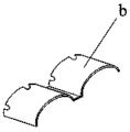
Fig. 6 is a schematic view of the arc-shaped shell b after shaping.
Fig. 7 is a schematic view of the motor casing c after wrapping a circle.
In the figure:
1-hydraulic station, 2-frame body, 3-base, 4-hydraulic cylinder, 5-punching mechanism, 51-mounting plate, 52-driving seat, 53-die holder, 54-upper die mechanism, 54 a-punching knife, 54 b-shaping upper die, 54 c-round-covered upper die, 55-guide column, 56-pressing block, 57-guide rod, 58-spring, 6-guide device, 7-lower die holder, 7 a-punching hole, 7 b-shaping lower die and 7 c-round-covered cylinder.
Detailed Description
The invention is further described below with reference to the accompanying drawings:
example (b):
as shown in figures 1 to 7
The utility model provides a full-automatic five metals continuous die mechanism, including hydraulic pressure station 1, frame body 2, base 3, pneumatic cylinder 4, punching press mechanism 5, guider 6 and die holder 7, hydraulic pressure station 1 set up in one side of frame body 2 to be connected with pneumatic cylinder 4 through high-pressure fuel pipe; the frame body 2 is arranged on the base 3 through bolts, and a hydraulic cylinder 4 is fixed at the top of the frame body 2; the stamping mechanism 5 is fixedly connected with a piston rod of the hydraulic cylinder 4; 4 guide devices 6 are adopted and are respectively arranged at four corners of the upper end of the base 3; the lower die holder 7 is arranged above the base 3 and is positioned right below the stamping mechanism 5.
The stamping mechanism 5 comprises a mounting plate 51, a driving seat 52, a die holder 53, an upper die mechanism 54, a guide post 55, a pressing block 56, a guide rod 57 and a spring 58, wherein the mounting plate 51 is fixed at the upper end of the driving seat 52; the die holder 53 is arranged below the driving seat 52 through a hanging bolt; the upper die mechanism 54 is connected with the die holder 53 in a sliding manner through a guide post 55 and a guide rod 57; the springs 58 are arranged between the die holder 53 and the upper die mechanism 54.
The bottom of the upper die mechanism 54 is sequentially provided with a punching knife 54a, a shaping upper die 54b and a rounding upper die 54c from left to right; the punching knife 54a is arranged in a convex shape; the shaping upper die 54b is provided with 2 concave cylinders; the upper round-covering die 54c is provided with a cylindrical groove.
The upper end of the lower die base 7 is sequentially provided with a punching hole 7a, a shaping lower die 7b and a wrapping cylinder 7c from left to right, and the punching hole 7a is a sunken slotted hole; the shaping lower die 7b is provided with 2 raised cylinders; the wrapping cylinder 7c is a cylinder made of 45# steel, and one end of the wrapping cylinder 7c is welded on the right side of the upper end of the lower die base 7.
The punching hole 7a, the shaping lower die 7b and the wrapping cylinder 7c are respectively matched with the punching knife 54a, the shaping upper die 54b and the wrapping cylinder 54 c.
Principle of operation
In the utility model, when in use, firstly, the raw material is sent into the space between the upper die mechanism and the lower die holder 7 through the continuous feeder, the hydraulic station 1 drives the hydraulic cylinder 4 to move, the punching mechanism 5 moves downwards, the upper die mechanism 54 is matched with the lower die holder 7, the punching knife 54a punches the raw material, thereby the raw material becomes a blank, along with the right movement of the raw material, after the blank after punching enters the space between the shaping upper die 54b and the shaping lower die 7b, the blank is pressed into the shaping lower die 7b by the shaping upper die 54b, a shell with 2 arc shapes is formed, the shell after shaping moves along with the continuous right movement of the raw material, the blank enters the space between the circle wrapping upper die 54c and the circle wrapping post 7c, the circle wrapping upper die 54c presses the shell downwards, under the matching of the circle wrapping post 7c, the circle wrapping of the shell is realized, thereby a motor shell is formed, the upper die mechanism and the lower die holder 7, the device has the advantages that the device utilization rate is effectively improved, repeated feeding and discharging are not needed, the processing time is greatly shortened, and the production efficiency is improved.
Utilize technical scheme, or technical personnel in the field are in the utility model discloses under technical scheme's the inspiration, design similar technical scheme, and reach above-mentioned technological effect, all fall into the utility model discloses a protection scope.
Claims (5)
1. The utility model provides a full-automatic five metals modulus of continuity mechanism which characterized in that: the stamping device comprises a hydraulic station (1), a frame body (2), a base (3), a hydraulic cylinder (4), a stamping mechanism (5), a guide device (6) and a lower die holder (7), wherein the hydraulic station (1) is arranged on one side of the frame body (2) and is connected with the hydraulic cylinder (4) through a high-pressure oil pipe; the frame body (2) is arranged on the base (3) through bolts, and a hydraulic cylinder (4) is fixed at the top of the frame body (2); the stamping mechanism (5) is fixedly connected with a piston rod of the hydraulic cylinder (4); 4 guide devices (6) are respectively arranged at four corners of the upper end of the base (3); the lower die holder (7) is arranged above the base (3) and is positioned right below the stamping mechanism (5).
2. The fully automatic hardware progressive die mechanism of claim 1, wherein: the stamping mechanism (5) comprises a mounting plate (51), a driving seat (52), a die holder (53), an upper die mechanism (54), a guide post (55), a pressing block (56), a guide rod (57) and a spring (58), wherein the mounting plate (51) is fixed at the upper end of the driving seat (52); the die holder (53) is arranged below the driving seat (52) through a hanging bolt; the upper die mechanism (54) is connected with the die holder (53) in a sliding way through a guide post (55) and a guide rod (57); the springs (58) are arranged between the die holder (53) and the upper die mechanism (54).
3. The fully automatic hardware progressive die mechanism of claim 2, wherein: the bottom of the upper die mechanism (54) is sequentially provided with a punching knife (54 a), a shaping upper die (54 b) and a rounding upper die (54 c) from left to right; the punching knife (54 a) is arranged to be convex; the shaping upper die (54 b) is set to be in a cylindrical shape with 2 recesses; the circle-wrapping upper die (54 c) is arranged into a cylindrical groove.
4. The fully automatic hardware progressive die mechanism of claim 1, wherein: the upper end of the lower die base (7) is sequentially provided with a punching hole (7 a), a shaping lower die (7 b) and a wrapping cylinder (7 c) from left to right, and the punching hole (7 a) is a sunken slotted hole; the shaping lower die (7 b) is set to be in a cylindrical shape with 2 bulges; the wrapping cylinder (7 c) is made of 45# steel, and one end of the wrapping cylinder (7 c) is welded on the right side of the upper end of the lower die base (7).
5. The fully automatic hardware progressive die mechanism of claim 4, wherein: the punching hole (7 a), the shaping lower die (7 b) and the wrapping cylinder (7 c) are respectively matched with the punching knife (54 a), the shaping upper die (54 b) and the wrapping cylinder upper die (54 c).
Priority Applications (1)
| Application Number | Priority Date | Filing Date | Title |
|---|---|---|---|
| CN202020030921.3U CN211413349U (en) | 2020-01-08 | 2020-01-08 | Full-automatic five metals modulus of continuity mechanism |
Applications Claiming Priority (1)
| Application Number | Priority Date | Filing Date | Title |
|---|---|---|---|
| CN202020030921.3U CN211413349U (en) | 2020-01-08 | 2020-01-08 | Full-automatic five metals modulus of continuity mechanism |
Publications (1)
| Publication Number | Publication Date |
|---|---|
| CN211413349U true CN211413349U (en) | 2020-09-04 |
Family
ID=72288113
Family Applications (1)
| Application Number | Title | Priority Date | Filing Date |
|---|---|---|---|
| CN202020030921.3U Active CN211413349U (en) | 2020-01-08 | 2020-01-08 | Full-automatic five metals modulus of continuity mechanism |
Country Status (1)
| Country | Link |
|---|---|
| CN (1) | CN211413349U (en) |
-
2020
- 2020-01-08 CN CN202020030921.3U patent/CN211413349U/en active Active
Similar Documents
| Publication | Publication Date | Title |
|---|---|---|
| CN201201030Y (en) | Nitrogen compacting mould for hot trimming and punching forgings | |
| CN203304417U (en) | Flip-over type piercing and blanking die | |
| CN206981539U (en) | Left and right brake-pedal support plate progressive die | |
| CN211413349U (en) | Full-automatic five metals modulus of continuity mechanism | |
| CN209792508U (en) | Double-punching forging die | |
| CN209935661U (en) | Prevent that waste material from blockking up type five metals stamping die | |
| CN209902035U (en) | Punching and blanking device for automobile sheet metal part | |
| CN217289996U (en) | Hardware stamping forming die | |
| CN208527844U (en) | A kind of stamping die with Anti-blockage function | |
| CN212551292U (en) | Mould with material returned protection | |
| CN214108509U (en) | Automatic panel stamping die of material loading | |
| CN211437741U (en) | Crossbeam continuous blanking die | |
| CN212397838U (en) | One-time forming compound die for side punching of bidirectional flanging belt | |
| CN211437782U (en) | Side pressure forming structure of die | |
| CN204486543U (en) | Telescopic compund die | |
| CN214720243U (en) | Main speed reduction internal straight tooth forging die | |
| CN110899499A (en) | Quick-change steel shell stretching combined die | |
| CN210614875U (en) | Die mechanism with rapidly replaced punch | |
| CN210523574U (en) | One-robot multi-station stamping die | |
| CN219052557U (en) | Stamping die for plate frame sheet metal machining | |
| CN210754633U (en) | Floating opposite punching die | |
| CN210059512U (en) | Stamping forming quick-change type tooth-drawing mechanism | |
| CN217252152U (en) | One-time upturning side belt punching and flanging die | |
| CN213350439U (en) | Shock absorber shell punching die | |
| CN111185515A (en) | Bar cutting die |
Legal Events
| Date | Code | Title | Description |
|---|---|---|---|
| GR01 | Patent grant | ||
| GR01 | Patent grant |