CN211400768U - Novel isothermal smelting aluminum melting furnace - Google Patents
Novel isothermal smelting aluminum melting furnace Download PDFInfo
- Publication number
- CN211400768U CN211400768U CN202020060158.9U CN202020060158U CN211400768U CN 211400768 U CN211400768 U CN 211400768U CN 202020060158 U CN202020060158 U CN 202020060158U CN 211400768 U CN211400768 U CN 211400768U
- Authority
- CN
- China
- Prior art keywords
- pipe
- box
- water tank
- wall
- communicated
- Prior art date
- Legal status (The legal status is an assumption and is not a legal conclusion. Google has not performed a legal analysis and makes no representation as to the accuracy of the status listed.)
- Active
Links
Images


Classifications
-
- Y—GENERAL TAGGING OF NEW TECHNOLOGICAL DEVELOPMENTS; GENERAL TAGGING OF CROSS-SECTIONAL TECHNOLOGIES SPANNING OVER SEVERAL SECTIONS OF THE IPC; TECHNICAL SUBJECTS COVERED BY FORMER USPC CROSS-REFERENCE ART COLLECTIONS [XRACs] AND DIGESTS
- Y02—TECHNOLOGIES OR APPLICATIONS FOR MITIGATION OR ADAPTATION AGAINST CLIMATE CHANGE
- Y02P—CLIMATE CHANGE MITIGATION TECHNOLOGIES IN THE PRODUCTION OR PROCESSING OF GOODS
- Y02P10/00—Technologies related to metal processing
- Y02P10/25—Process efficiency
Abstract
The utility model discloses a novel isothermal smelting aluminum melting furnace in the technical field of aluminum melting furnaces, which comprises a furnace body, wherein a smoke exhaust pipe is arranged on the left side of the top of the furnace body, the left end of the smoke exhaust pipe is communicated with a connecting pipe, the bottom end of the connecting pipe is communicated with a feeding bin arranged on the outer wall of the furnace body, the bottom end of the feeding bin is provided with a feeding pipe, the bottom end of the feeding pipe is communicated with the furnace body, the left bottom end of the feeding bin is provided with an air inlet pipe, the bottom end of the air inlet pipe is communicated with an air inlet of a fan, the fan is arranged on the outer wall of a water tank, an air supply outlet of the fan is communicated with an air supply pipe, through the arrangement of the water tank and a spiral pipe, the residual heat in high-temperature flue gas heats the water in the water tank, the heated water is, facilitating efficient heating of the water.
Description
Technical Field
The utility model relates to a melt aluminium stove technical field, specifically be novel isothermal melting melts aluminium stove.
Background
The aluminum melting furnace is a novel efficient energy-saving furnace developed according to an aluminum melting process, the traditional isothermal melting aluminum melting furnace can generate a large amount of high-temperature smoke when being used, the high-temperature smoke is directly discharged into the air, the environment is polluted, a large amount of heat energy is contained in the high-temperature smoke, a large amount of heat is easily lost, resources are wasted, and the novel isothermal melting aluminum melting furnace is provided for the purpose.
SUMMERY OF THE UTILITY MODEL
An object of the utility model is to provide a novel isothermal melting aluminium melting furnace to solve the problem that proposes among the above-mentioned background art.
In order to achieve the above object, the utility model provides a following technical scheme: novel isothermal smelting melts aluminium stove, the induction cooker comprises a cooker bod, the top left side of furnace body is provided with the pipe of discharging fume, the left end and the connecting pipe intercommunication of the pipe of discharging fume, the connecting pipe bottom communicates with the feeding storehouse of installing on the furnace body outer wall, the bottom in feeding storehouse is provided with the inlet pipe, the bottom and the furnace body intercommunication of inlet pipe, the left side bottom in feeding storehouse is provided with the intake pipe, the bottom of intake pipe and the air intake intercommunication of fan, the fan sets up on the outer wall of water tank, the supply-air outlet intercommunication of fan has the air supply pipe, the left end of air supply pipe runs through water tank and spiral pipe intercommunication, and the spiral pipe setting is on the inner wall of water tank, the bottom of water tank is provided with the outlet pipe, the top left end intercommunication of spiral pipe has the transmission pipe, the transmission pipe.
Preferably, the feeding bin comprises a shell, a feeding hole is formed in the left side of the top of the shell, a first motor is arranged at the middle end of the top of the shell, a stirring shaft is connected to a power rotating shaft at the bottom of the first motor and arranged inside the shell, and stirring blades are uniformly welded to the outer wall of the stirring shaft.
Preferably, the purifying box comprises a box body, a supporting plate is arranged on the inner wall of the left side of the box body, an air outlet of the conveying pipe is positioned above the supporting plate, a filter screen is vertically arranged on the right side of the top of the supporting plate, the top end of the filter screen is connected with the inner wall of the box body, the left side of the box body is provided with a second motor, a power rotating shaft at the right end of the second motor is connected with a rotating shaft, the rotating shaft is positioned in the box body, the right end of the rotating shaft is connected with a brush head, the right side of the brush head is uniformly provided with brushes which are contacted with the filter screen, the supporting plate is provided with a through groove, the through groove is communicated with a dust collecting box movably arranged on the inner wall of the bottom of the box body, an adsorption layer is arranged on the inner wall of the box body, and the adsorption layer is located the right side of filter screen, the box is located the right-hand member of adsorption layer and is provided with photocatalyst layer, the right-hand member of box is provided with the blast pipe.
Preferably, the front side of the box body is hinged with a box door through a hinge, and the box door is provided with an observation window.
Preferably, the top end of the left side of the water tank is communicated with a water inlet pipe, and the bottom end of the water outlet pipe is provided with a sealing cover.
Preferably, the bottom of furnace body is provided with the bin outlet, and the bottom of bin outlet is provided with the bottom.
Compared with the prior art, the beneficial effects of the utility model are that:
1. the high-temperature flue gas discharged by the smoke exhaust pipe enters the feeding bin through the connecting pipe by the operation of the fan, the high-temperature flue gas can heat the waste aluminum due to the good heat conductivity of the waste aluminum, the heated waste aluminum can reduce the heat required by the melting treatment of the waste aluminum, so that the energy consumption of the furnace body can be reduced, the recycling of the heat energy of the high-temperature flue gas is realized, and the waste aluminum and the high-temperature flue gas in the feeding bin are continuously stirred and rolled by the arrangement of the first motor, the stirring shaft and the stirring blades, so that the contact area of the waste aluminum and the high-temperature flue gas can be increased, and more heat in the high-temperature flue gas can be guided away by the waste aluminum;
2. the water tank and the spiral pipe are arranged, so that the residual heat in the high-temperature flue gas heats the water in the water tank, the heated water is convenient for a factory to use, the utilization rate of the heat in the high-temperature flue gas is high, the spiral pipe can increase the contact area with the water, and the water is convenient to heat effectively;
3. through being provided with the filter screen, can filter the dust particulate matter in the flue gas, through being provided with adsorbed layer and photocatalyst layer, can adsorb the decomposition to the toxic gas in the flue gas, avoid the polluted environment.
Drawings
FIG. 1 is a schematic structural view of the present invention;
FIG. 2 is a schematic view of the structure of the feeding bin of the present invention;
FIG. 3 is a schematic view of the internal structure of the purification box of the present invention;
fig. 4 is the external structure schematic diagram of the purification box of the present invention.
In the figure: 1. a furnace body; 2. a smoke exhaust pipe; 3. a connecting pipe; 4. a feeding bin; 41. a housing; 42. a feed inlet; 43. a first motor; 44. a stirring shaft; 45. stirring blades; 5. a feed pipe; 6. an air inlet pipe; 7. a fan; 8. a water tank; 9. an air supply pipe; 10. a water outlet pipe; 11. a spiral tube; 12. a conveying pipe; 13. a purification box; 131. a box body; 132. a support plate; 133. filtering with a screen; 134. a second motor; 135. a bristle head; 136. a dust collecting box; 137. an adsorption layer; 138. a photocatalyst layer; 139. an exhaust pipe; 1310. a box door; 1311. and (4) an observation window.
Detailed Description
The technical solutions in the embodiments of the present invention will be described clearly and completely with reference to the accompanying drawings in the embodiments of the present invention, and it is obvious that the described embodiments are only some embodiments of the present invention, not all embodiments. Based on the embodiments in the present invention, all other embodiments obtained by a person skilled in the art without creative work belong to the protection scope of the present invention.
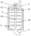
The utility model provides a technical scheme: the novel isothermal smelting aluminum melting furnace comprises a furnace body 1, wherein a smoke exhaust pipe 2 is arranged on the left side of the top of the furnace body 1 and used for exhausting high-temperature smoke, the left end of the smoke exhaust pipe 2 is communicated with a connecting pipe 3, the bottom end of the connecting pipe 3 is communicated with a feeding bin 4 arranged on the outer wall of the furnace body 1, the feeding bin 4 is used for feeding materials into the furnace body 1, a feeding pipe 5 is arranged at the bottom end of the feeding bin 4, the bottom end of the feeding pipe 5 is communicated with the furnace body 1, and waste aluminum passing through the feeding bin 4 enters the furnace body 1 through the feeding pipe 5;
referring to fig. 1, an air inlet pipe 6 is arranged at the bottom end of the left side of a feeding bin 4, a porous partition plate is arranged at the right end of the air inlet pipe 6, waste aluminum can be prevented from entering the air inlet pipe 6, the bottom end of the air inlet pipe 6 is communicated with an air inlet of a fan 7, the fan 7 is arranged on the outer wall of a water tank 8, the fan 7 is controlled by an external power switch and is externally connected with a power lead, an air supply outlet of the fan 7 is communicated with an air supply pipe 9, the left end of the air supply pipe 9 penetrates through the water tank 8 to be communicated with a spiral pipe 11, the spiral pipe 11 is arranged on the inner wall of the water tank 8, the spiral pipe 11 is an aluminum pipeline and has good thermal conductivity, water is arranged in the water tank 8, heat in high-temperature flue gas enters the spiral pipe 11 through the air inlet pipe 6 and the air supply pipe 9, the heat in the water, when a factory needs to use hot water, the hot water can be taken out through the water outlet pipe 10, and the spiral pipe 11 can increase the contact area with the water, so that the water can be effectively heated;
referring to fig. 1, the left end of the top of the spiral pipe 11 is communicated with a transmission pipe 12, the transmission pipe 12 penetrates through the water tank 8 and is communicated with a purification box 13 installed on the top of the water tank 8, and heat in the high-temperature flue gas is recycled, enters the purification box 13 through the transmission pipe 12, is purified and then is discharged.
Referring to fig. 2, the feeding bin 4 includes a housing 41, a feeding port 42 is disposed on the left side of the top of the housing 41, the feeding port 42 is used for feeding materials, a top cover is disposed on the top of the feeding port 42 to seal the feeding port 42 and prevent high-temperature flue gas from escaping, a first motor 43 is disposed at the middle end of the top of the housing 41, the first motor 43 is controlled by an external power switch and is connected with an external power lead, a power rotating shaft at the bottom of the first motor 43 is connected with a stirring shaft 44, the first motor 43 is connected with the power rotating shaft through a speed reducer, the stirring shaft 44 is disposed inside the housing 41, stirring blades 45 are uniformly welded on the outer wall of the stirring shaft 44, the first motor 43 drives the stirring shaft 44 to rotate, so that the stirring blades 45 rotate, and further waste aluminum and high-temperature flue gas in the feeding bin are continuously stirred and rolled, thereby increasing the, so that more heat in the high-temperature flue gas can be conducted away by the waste aluminum;
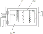
referring to fig. 3, the purifying box 13 includes a box body 131, a supporting plate 132 is disposed on the left inner wall of the box body 131, an air outlet of the transmission pipe 12 is located above the supporting plate 132, a filter screen 133 is vertically disposed on the right side of the top of the supporting plate 132, the top end of the filter screen 133 is connected to the inner wall of the box body 131, the filter screen 133 is used for filtering dust particles in the flue gas, a second motor 134 is disposed on the left side of the box body 131, the second motor 134 is controlled by an external power switch and is connected to an external power wire, a power rotating shaft at the right end of the second motor 134 is connected to a rotating shaft, the rotating shaft is located inside the box body 131, the second motor 134 is connected to a power rotating shaft through a speed reducer, a brush head 135 is connected to the right end of the rotating shaft, the height of the brush head 135 is the same as, the second motor 134 is started, so that the rotating shaft rotates, and further the brush head 135 rotates, thereby the dust on the filter screen 133 is brushed off through the brush on the brush head 135, the support plate 132 is provided with a through groove which is communicated with a dust collecting box 136 movably arranged on the inner wall of the bottom of the box body 131, the brushed off dust enters the dust collecting box 136 through the through groove, the dust collecting box 136 is made of transparent plastic, so that the volume of the internal dust is convenient to know, thereby being convenient for taking out and cleaning in time, the inner wall of the box body 131 is provided with an adsorption layer 137, the adsorption layer 137 is positioned at the right side of the filter screen 133, the adsorption layer 137 is filled with active carbon, toxic gas in the smoke can be adsorbed through the adsorption layer 137, the box body 131 is provided with a photocatalyst layer 138 at the right end of the adsorption layer 137, the box body 131 is provided with an ultraviolet lamp at the right side of the photocatalyst layer, toxic gas in the flue gas can be further adsorbed and decomposed to avoid environmental pollution, the ultraviolet lamp is controlled by an external power switch and is externally connected with a power lead, the right end of the box body 131 is provided with an exhaust pipe 139, and the purified high-temperature flue gas is discharged through the exhaust pipe 139;
referring to fig. 4, a door 1310 is hinged to the front side of the case 131 through a hinge, the door 1310 is provided with an observation window 1311, the inside of the case 131 can be known conveniently through the observation window 1311, and the case 131 can be opened conveniently to take out the dust collecting box 136 through the door 1310;
referring to fig. 1, a water inlet pipe is communicated with the top end of the left side of the water tank 8, a sealing cover is arranged at the bottom end of the water outlet pipe 10, the water inlet pipe is used for adding water into the water tank 8, and the sealing cover can prevent heat loss of the heated water;
referring to fig. 1, a discharge outlet is disposed at the bottom end of a furnace body 1, and a bottom cover is disposed at the bottom of the discharge outlet for discharging.
The working principle is as follows: when the high-temperature flue gas heating furnace is used, the fan 7 is started, high-temperature flue gas enters the connecting pipe 3 through the exhaust pipe 2 and then enters the feeding bin 4, the high-temperature flue gas can heat the waste aluminum in the feeding bin 4 due to good heat conductivity of the waste aluminum, the heated waste aluminum can reduce the heat required by the melting treatment of the waste aluminum, the energy consumption of the furnace body 1 can be reduced, the heat energy recycling of the high-temperature flue gas is realized, the first motor 43 is started, the stirring shaft 44 drives the stirring blades 45 to rotate, the waste aluminum and the high-temperature flue gas in the feeding bin 4 are continuously stirred and rolled, the contact area of the waste aluminum and the high-temperature flue gas can be increased, more heat in the high-temperature flue gas can be conducted away by the waste aluminum, then the high-temperature flue gas enters the spiral pipe 11 made of aluminum through the air inlet pipe 6 and the air supply pipe 9, and therefore the residual heat in the high-temperature flue, the heated water is convenient for the factory to use, thereby leading the heat utilization rate in the high-temperature flue gas to be high, the spiral pipe 11 can increase the contact area with the water, being convenient for effectively heating the water, finally the high-temperature flue gas enters the purifying box 13 through the transmission pipe 12, the dust particles in the smoke are filtered by the filter 133, and the rotating shaft is driven to rotate by the second motor 134, so that the brush head 135 rotates, thereby brushing off the dust on the filter mesh 133 through the bristles on the bristles 135, the brushed-off dust entering the dust collecting case 136 through the through groove to be collected, by opening the door 1310, the dust collecting box 136 can be taken out, thereby being convenient for taking out and cleaning in time, then the toxic gas in the smoke can be adsorbed through the adsorption layer 137, the poisonous gas in the flue gas can be further adsorbed and decomposed through the photocatalyst layer 138, so that the environment pollution is avoided, and the purified high-temperature flue gas is finally discharged through the exhaust pipe 139.
Although embodiments of the present invention have been shown and described, it will be appreciated by those skilled in the art that changes, modifications, substitutions and alterations can be made in these embodiments without departing from the principles and spirit of the invention, the scope of which is defined in the appended claims and their equivalents.
Claims (6)
1. Novel isothermal melting aluminium melting furnace, including furnace body (1), its characterized in that: the utility model discloses a flue gas boiler, including furnace body (1), the top left side of furnace body (1) is provided with and discharges fume tub (2), the left end and the connecting pipe (3) intercommunication of tub (2) of discharging fume, connecting pipe (3) bottom and feeding storehouse (4) intercommunication of installing on the furnace body (1) outer wall, the bottom in feeding storehouse (4) is provided with inlet pipe (5), the bottom and furnace body (1) intercommunication of inlet pipe (5), the left side bottom in feeding storehouse (4) is provided with intake pipe (6), the bottom of intake pipe (6) and the air intake intercommunication of fan (7), fan (7) set up on the outer wall of water tank (8), the supply-air outlet intercommunication of fan (7) has air supply pipe (9), the left end of air supply pipe (9) runs through water tank (8) and spiral pipe (11) intercommunication, and spiral pipe (11) set up on the inner wall of water tank (8), the bottom of water tank (8) is provided with outlet pipe, the left end of the top of the spiral pipe (11) is communicated with a transmission pipe (12), and the transmission pipe (12) penetrates through the water tank (8) and is communicated with a purification box (13) arranged at the top of the water tank (8).
2. The novel isothermal smelting and aluminum melting furnace according to claim 1, characterized in that: the feeding bin (4) comprises a shell (41), a feeding hole (42) is formed in the left side of the top of the shell (41), a first motor (43) is arranged at the middle end of the top of the shell (41), a power rotating shaft at the bottom of the first motor (43) is connected with a stirring shaft (44), the stirring shaft (44) is arranged inside the shell (41), and stirring blades (45) are uniformly welded on the outer wall of the stirring shaft (44).
3. The novel isothermal smelting and aluminum melting furnace according to claim 1, characterized in that: the purifying box (13) comprises a box body (131), a supporting plate (132) is arranged on the inner wall of the left side of the box body (131), an air outlet of the transmission pipe (12) is positioned above the supporting plate (132), a filter screen (133) is vertically arranged on the right side of the top of the supporting plate (132), the top end of the filter screen (133) is connected to the inner wall of the box body (131), a second motor (134) is arranged on the left side of the box body (131), a power rotating shaft at the right end of the second motor (134) is connected with a rotating shaft, the rotating shaft is positioned inside the box body (131), a brush head (135) is connected to the right end of the rotating shaft, brushes which are in contact with the filter screen (133) are uniformly arranged on the right side of the brush head (135), a through groove is arranged on the supporting plate (132), and is communicated with a dust collecting box, be provided with adsorbed layer (137) on the inner wall of box (131), and adsorbed layer (137) are located the right side of filter screen (133), box (131) are provided with photocatalyst layer (138) in the right-hand member of adsorbed layer (137), the right-hand member of box (131) is provided with blast pipe (139).
4. The novel isothermal melting and aluminum melting furnace of claim 3, wherein: the front side of the box body (131) is hinged with a box door (1310) through a hinge, and the box door (1310) is provided with an observation window (1311).
5. The novel isothermal smelting and aluminum melting furnace according to claim 1, characterized in that: the left side top of water tank (8) intercommunication has the inlet tube, the bottom of outlet pipe (10) is provided with sealed lid.
6. The novel isothermal smelting and aluminum melting furnace according to claim 1, characterized in that: the bottom of furnace body (1) is provided with the bin outlet, and the bottom of bin outlet is provided with the bottom.
Priority Applications (1)
| Application Number | Priority Date | Filing Date | Title |
|---|---|---|---|
| CN202020060158.9U CN211400768U (en) | 2020-01-13 | 2020-01-13 | Novel isothermal smelting aluminum melting furnace |
Applications Claiming Priority (1)
| Application Number | Priority Date | Filing Date | Title |
|---|---|---|---|
| CN202020060158.9U CN211400768U (en) | 2020-01-13 | 2020-01-13 | Novel isothermal smelting aluminum melting furnace |
Publications (1)
| Publication Number | Publication Date |
|---|---|
| CN211400768U true CN211400768U (en) | 2020-09-01 |
Family
ID=72217679
Family Applications (1)
| Application Number | Title | Priority Date | Filing Date |
|---|---|---|---|
| CN202020060158.9U Active CN211400768U (en) | 2020-01-13 | 2020-01-13 | Novel isothermal smelting aluminum melting furnace |
Country Status (1)
| Country | Link |
|---|---|
| CN (1) | CN211400768U (en) |
Cited By (1)
| Publication number | Priority date | Publication date | Assignee | Title |
|---|---|---|---|---|
| CN115638664A (en) * | 2022-12-26 | 2023-01-24 | 河南省远洋粉体科技股份有限公司 | Heat energy-saving system for aluminum-based alloy powder production |
-
2020
- 2020-01-13 CN CN202020060158.9U patent/CN211400768U/en active Active
Cited By (1)
| Publication number | Priority date | Publication date | Assignee | Title |
|---|---|---|---|---|
| CN115638664A (en) * | 2022-12-26 | 2023-01-24 | 河南省远洋粉体科技股份有限公司 | Heat energy-saving system for aluminum-based alloy powder production |
Similar Documents
| Publication | Publication Date | Title |
|---|---|---|
| CN112774348B (en) | Industrial waste gas purifies uses high-efficiency processing device | |
| CN211400768U (en) | Novel isothermal smelting aluminum melting furnace | |
| CN109899799B (en) | Environment-friendly incineration device for rural garbage treatment | |
| CN208975514U (en) | A kind of heat energy from waste gas environmental protection utilizes device | |
| CN208090704U (en) | A kind of natural gas energy-saving, environmental protection boiler | |
| CN110986045A (en) | Household garbage recycling device | |
| CN215849116U (en) | Surface melting device for recycling waste electric wires | |
| CN216307804U (en) | Flue gas high temperature dust removal denitration integration garbage incinerator | |
| CN206176346U (en) | Stew pot stove is fired in fire -resistant energy -conservation | |
| CN210833106U (en) | Special high-efficient circulation processing apparatus of flue gas of pyrolysis gasifier | |
| CN212602724U (en) | Plasticating device for devulcanizing waste rubber into reclaimed rubber | |
| CN211400293U (en) | Energy-concerving and environment-protective boiler of PLC control | |
| CN214680685U (en) | Low-energy-consumption waste gas treatment control system | |
| CN217636573U (en) | Natural gas hot-blast furnace for fertilizer production | |
| CN218721495U (en) | High-temperature gasification low-oxygen combustion device | |
| CN213193200U (en) | Refuse treatment is with burning flue gas deacidification device | |
| CN217763507U (en) | Black smoke-free environment-friendly energy-saving boiler with fuel fully combusted | |
| CN210861699U (en) | Energy-saving environment-friendly boiler | |
| CN220229234U (en) | Boiler tail gas treatment pipeline | |
| CN216281460U (en) | New energy-saving environment-friendly combustion furnace | |
| CN215822630U (en) | Flue gas filtering device for heat storage oxidation furnace | |
| CN212177221U (en) | Garbage pyrolysis waste heat power generation device | |
| CN217737237U (en) | Efficient environment-friendly energy-saving emission-reducing gas boiler equipment | |
| CN217764566U (en) | Gas waste heat environmental protection recovery unit | |
| CN213577490U (en) | Garbage disposal burns burning furnace with high-efficient environmental protection |
Legal Events
| Date | Code | Title | Description |
|---|---|---|---|
| GR01 | Patent grant | ||
| GR01 | Patent grant |