CN211382142U - Rubberizing machine for cold compress manufacturing - Google Patents
Rubberizing machine for cold compress manufacturing Download PDFInfo
- Publication number
- CN211382142U CN211382142U CN201922303420.8U CN201922303420U CN211382142U CN 211382142 U CN211382142 U CN 211382142U CN 201922303420 U CN201922303420 U CN 201922303420U CN 211382142 U CN211382142 U CN 211382142U
- Authority
- CN
- China
- Prior art keywords
- plate
- rubberizing
- pipe
- platform
- lower pressing
- Prior art date
- Legal status (The legal status is an assumption and is not a legal conclusion. Google has not performed a legal analysis and makes no representation as to the accuracy of the status listed.)
- Expired - Fee Related
Links
Images


Abstract
The utility model relates to a cold compress processing device technical field specifically discloses a rubberizing machine for cold compress manufacturing, including rubberizing supporting box, rubberizing supporting box top is provided with the support frame, is provided with down-pressing cylinder on the roof of support frame, and the piston rod of down-pressing cylinder passes the roof and is connected with the connecting plate, and the connecting plate bottom is connected with the holding down plate, and rubberizing supporting box top intermediate position department is provided with the placing platform, and the placing platform both ends all are provided with vertical supporting side plate, and one side of two supporting side plates all is connected with the flexible pipe of level setting, and flexible pipe one end is rotated and is connected with the clamp bolt of vertical setting, and the clamp bolt bottom is connected with the lower pressure disk; place the platform and be hollow structure, place bench evenly distributed and have a plurality of air vents, place and be provided with a plurality of covers of bleeding in the platform, every cover one end of bleeding all is connected with the bleeder, through the cover of bleeding of placing the platform, conveniently adsorb to cold compress and fix on placing the platform, prevent to shift.
Description
Technical Field
The utility model relates to a cold compress processing technical field specifically is a cold compress is made and is used coating machine.
Background
The cold compress is formed by improving according to the traditional cold compress mode, and consists of a back lining layer, a gel layer and an anti-sticking layer, and a gluing machine is needed for manufacturing the cold compress. When the existing adhesive tape sticking machine is used, cold application is directly placed on a workbench, then adhesive tape sticking work is carried out, fixed cold application is not carried out, cold application displacement is easily caused in the adhesive tape sticking process, adhesive tape sticking failure is caused, and loss is caused.
SUMMERY OF THE UTILITY MODEL
An object of the utility model is to provide a cold compress is rubberizing machine for manufacturing to solve the problem that proposes among the above-mentioned background art.
In order to achieve the above object, the utility model provides a following technical scheme: a rubberizing machine for cold compress manufacturing comprises a rubberizing supporting box, wherein a supporting frame is arranged at the top of the rubberizing supporting box, a lower pressing cylinder is arranged on a top plate of the supporting frame, a piston rod of the lower pressing cylinder penetrates through the top plate to be connected with a connecting plate, the bottom of the connecting plate is connected with a lower pressing plate, a placing table is arranged in the middle of the top of the rubberizing supporting box, vertical supporting side plates are arranged at two ends of the placing table, a horizontally arranged telescopic pipe is connected to one side of each of the two supporting side plates, one end of each telescopic pipe is rotatably connected with a vertically arranged compression bolt, and the bottom of each; place the platform and be hollow structure, place bench evenly distributed and have a plurality of air vents, place and be provided with a plurality of suction hoods in the platform, every suction hood one end all is connected with the bleeder, and the bleeder passes the circular port intercommunication that sets up on the roof of rubberizing supporting box and the connecting pipe, and the circular port and the exhaust tube intercommunication that the bottom of connecting pipe set up, and the exhaust tube communicates with the one end of aspiration pump, and the aspiration pump setting is on the bottom plate of rubberizing supporting box.
Preferably, the bottom of the lower pressing plate is provided with a plurality of hemispherical bulges, the top of the lower pressing plate is provided with a convex column, and the bottom of the connecting plate is provided with a column hole which is matched with the convex column in an inserting manner.
Preferably, all be provided with a plurality of and connecting bolt threaded connection's screw on connecting plate and the holding down plate, the holding down plate passes through the cooperation setting of connecting bolt and screw at the bottom of connecting plate.
Preferably, the telescopic pipe consists of a bottom pipe and a sliding pipe, one end of the sliding pipe is connected in the bottom pipe in a sliding mode, and the bottom pipe is provided with a screw hole in threaded connection with the locking bolt.
Preferably, the top end of the compression bolt is provided with a connecting column, and the top of the connecting column is connected with a rotating disc.
Compared with the prior art, the beneficial effects of the utility model are that: the cold compress patch is convenient to adsorb and fix on the placing table through the air exhaust cover in the placing table to prevent displacement, and the compression bolts are used to conveniently compress two ends of the cold compress patch, prevent the cold compress patch from displacing and facilitate the gluing work; can dismantle the connecting plate and the holding down plate of connection, conveniently change the holding down plate of unidimensional according to the size of cold application, be convenient for go on cold application rubberizing work.
Drawings
Fig. 1 is a schematic view of the overall structure of the present invention;
fig. 2 is a schematic view of the telescopic tube structure of the present invention;
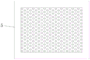
fig. 3 is a top view of the placing table of the present invention.
In the figure: 1. sticking a glue supporting box; 2. a support frame; 3. a lower pressing plate; 4. pressing down the air cylinder; 5. a placing table; 6. a connecting plate; 7. a connecting bolt; 8. a convex column; 9. an air pump; 10. an air extraction hood; 11. a connecting pipe; 12. supporting the side plates; 13. a telescopic pipe; 14. a hold-down bolt; 15. a protrusion; 16. a lower platen; 17. and (6) rotating the disc.
Detailed Description
The technical solutions in the embodiments of the present invention will be described clearly and completely with reference to the accompanying drawings in the embodiments of the present invention, and it is obvious that the described embodiments are only some embodiments of the present invention, not all embodiments. Based on the embodiments in the present invention, all other embodiments obtained by a person skilled in the art without creative work belong to the protection scope of the present invention.
In the description of the present invention, it should be noted that the terms "vertical", "upper", "lower", "horizontal", and the like indicate orientations or positional relationships based on the orientations or positional relationships shown in the drawings, and are only for convenience of description and simplification of description, but do not indicate or imply that the device or element referred to must have a specific orientation, be constructed in a specific orientation, and be operated, and thus should not be construed as limiting the present invention.
In the description of the present invention, it should also be noted that, unless otherwise explicitly specified or limited, the terms "disposed," "mounted," "connected," and "connected" are to be construed broadly, e.g., as meaning either a fixed connection, a removable connection, or an integral connection; can be mechanically or electrically connected; they may be connected directly or indirectly through intervening media, or they may be interconnected between two elements. The specific meaning of the above terms in the present invention can be understood according to specific situations by those skilled in the art.
Referring to fig. 1-3, the present invention provides a technical solution: a rubberizing machine for cold compress manufacturing comprises a rubberizing supporting box 1, wherein a supporting frame 2 is arranged at the top of the rubberizing supporting box 1, a downward pressing cylinder 4 is arranged on a top plate of the supporting frame 2, a piston rod of the downward pressing cylinder 4 penetrates through the top plate to be connected with a connecting plate 6, the bottom of the connecting plate 6 is connected with a downward pressing plate 3, a placing table 5 is arranged at the middle position of the top of the rubberizing supporting box 1, vertical supporting side plates 12 are arranged at two ends of the placing table 5, a horizontally arranged telescopic pipe 13 is connected to one side of each of the two supporting side plates 12, a vertically arranged compression bolt 14 is rotatably connected to one end of each telescopic pipe 13, and a lower pressing plate 16 is connected to; place platform 5 and be hollow structure, place evenly distributed on platform 5 and be provided with a plurality of air vents, place and be provided with a plurality of suction hoods 10 in the platform 5, every suction hood 10 one end all is connected with the bleeder, the bleeder passes the circular port intercommunication that sets up on the roof of rubberizing supporting box 1 and the connecting pipe 11, the circular port and the exhaust tube intercommunication of the bottom setting of connecting pipe 11, and the one end intercommunication of exhaust tube and aspiration pump 9, aspiration pump 9 sets up on the bottom plate of rubberizing supporting box 1, through the suction hood 10 in placing platform 5, it fixes on placing platform 5 to conveniently adsorb the cold application, prevent the aversion, reuse clamp bolt 14, conveniently compress tightly the both ends of cold application, prevent the cold application aversion, make things convenient for going on of rubberizing work.
The bottom of the lower pressing plate 3 is provided with a plurality of hemispherical protrusions 15, glue can be conveniently pasted, the top of the lower pressing plate 3 is provided with a convex column 8, the bottom of the connecting plate 6 is provided with a column hole matched with the convex column 8 in an inserting mode, and the lower pressing plate 3 can be conveniently located through the cooperation of the convex column 8 and the column hole.
All be provided with a plurality of and connecting bolt 7 threaded connection's screw on connecting plate 6 and the holding down plate 3, holding down plate 3 sets up in the bottom of connecting plate 6 through the cooperation of connecting bolt 7 and screw, through connecting bolt 7, will hold down plate 3 and connecting plate 3 and connect.
The telescopic pipe 13 consists of a bottom pipe and a sliding pipe, one end of the sliding pipe is connected in the bottom pipe in a sliding mode, a screw hole in threaded connection with a locking bolt is formed in the bottom pipe, the length of the telescopic pipe 13 is adjusted according to the size of the cold compress application, and the telescopic pipe is fixed through rotation of the locking bolt.
The top end of the pressing bolt 14 is provided with a connecting column, the top of the connecting column is connected with a rotating disc 17, and the rotating disc 17 is manually driven to rotate to drive the pressing bolt 14 to rotate.
The working principle is as follows: when the cold compress machine is used, an external power supply of the equipment is connected, the air pump 9 is opened according to the size of the cold compress, the cold compress placed on the placing table 5 is adsorbed and fixed through the air exhaust pipe, the connecting pipe 11, the branch pipe and the air exhaust cover 10, the length of the telescopic pipe 13 is adjusted until the lower pressing plate 16 moves to the two ends of the cold compress, the length of the telescopic pipe 13 is fixed, the rotating disc 17 is manually driven to rotate, the pressing bolt 14 starts to rotate until the lower pressing plate 16 is pressed down to be in contact with the cold compress, the two ends of the cold compress are pressed, the proper lower pressing plate 3 is selected according to the size of the cold compress, the lower pressing plate 3 is in inserting fit with the column hole at the bottom of the connecting plate 6 through the convex column 8, the position of the lower pressing plate 3 is positioned, the connecting plate 6 is connected with the lower pressing plate 3 through the connecting bolt 7, the lower pressing cylinder 4 is controlled to work, the lower pressing plate 3, the lower press plate 3 descends to carry out rubberizing processing.
It is worth noting that: the whole device is controlled by the external power supply, and the equipment matched with the external power supply is common equipment, so that the device belongs to the prior mature technology, and the electrical connection relation and the specific circuit structure are not repeated.
Although embodiments of the present invention have been shown and described, it will be appreciated by those skilled in the art that changes, modifications, substitutions and alterations can be made in these embodiments without departing from the principles and spirit of the invention, the scope of which is defined in the appended claims and their equivalents.
Claims (5)
1. The utility model provides a cold compress is rubberizing machine for manufacturing, includes rubberizing supporting box (1), its characterized in that: the top of the rubberizing supporting box (1) is provided with a supporting frame (2), a top plate of the supporting frame (2) is provided with a lower pressing cylinder (4), a piston rod of the lower pressing cylinder (4) penetrates through the top plate to be connected with a connecting plate (6), the bottom of the connecting plate (6) is connected with a lower pressing plate (3), a placing table (5) is arranged in the middle of the top of the rubberizing supporting box (1), two ends of the placing table (5) are respectively provided with a vertical supporting side plate (12), one side of each of the two supporting side plates (12) is respectively connected with a horizontally arranged telescopic pipe (13), one end of each telescopic pipe (13) is rotatably connected with a vertically arranged pressing bolt (14), and the bottom of each pressing bolt (; place platform (5) and be hollow structure, it has a plurality of air vents to place evenly distributed on platform (5), it is provided with a plurality of suction hoods (10) to place platform (5), every suction hood (10) one end all is connected with the bleeder, the bleeder passes the circular port intercommunication that sets up on roof and the connecting pipe (11) of rubberizing supporting box (1), the circular port and the exhaust tube intercommunication that the bottom of connecting pipe (11) set up, and the one end intercommunication of exhaust tube and aspiration pump (9), aspiration pump (9) set up on the bottom plate of rubberizing supporting box (1).
2. The adhesive coating machine for cold application manufacturing according to claim 1, characterized in that: the bottom of the lower pressing plate (3) is provided with a plurality of hemispherical bulges (15), the top of the lower pressing plate (3) is provided with a convex column (8), and the bottom of the connecting plate (6) is provided with a column hole which is in plug-in fit with the convex column (8).
3. The adhesive coating machine for cold application manufacturing according to claim 1, characterized in that: a plurality of screw holes in threaded connection with the connecting bolts (7) are formed in the connecting plate (6) and the lower pressing plate (3), and the lower pressing plate (3) is arranged at the bottom of the connecting plate (6) through the matching of the connecting bolts (7) and the screw holes.
4. The adhesive coating machine for cold application manufacturing according to claim 1, characterized in that: the telescopic pipe (13) consists of a bottom pipe and a sliding pipe, one end of the sliding pipe is connected in the bottom pipe in a sliding mode, and a screw hole in threaded connection with the locking bolt is formed in the bottom pipe.
5. The adhesive coating machine for cold application manufacturing according to claim 1, characterized in that: the top end of the hold-down bolt (14) is provided with a connecting column, and the top of the connecting column is connected with a rotating disc (17).
Priority Applications (1)
| Application Number | Priority Date | Filing Date | Title |
|---|---|---|---|
| CN201922303420.8U CN211382142U (en) | 2019-12-19 | 2019-12-19 | Rubberizing machine for cold compress manufacturing |
Applications Claiming Priority (1)
| Application Number | Priority Date | Filing Date | Title |
|---|---|---|---|
| CN201922303420.8U CN211382142U (en) | 2019-12-19 | 2019-12-19 | Rubberizing machine for cold compress manufacturing |
Publications (1)
| Publication Number | Publication Date |
|---|---|
| CN211382142U true CN211382142U (en) | 2020-09-01 |
Family
ID=72218998
Family Applications (1)
| Application Number | Title | Priority Date | Filing Date |
|---|---|---|---|
| CN201922303420.8U Expired - Fee Related CN211382142U (en) | 2019-12-19 | 2019-12-19 | Rubberizing machine for cold compress manufacturing |
Country Status (1)
| Country | Link |
|---|---|
| CN (1) | CN211382142U (en) |
Cited By (1)
| Publication number | Priority date | Publication date | Assignee | Title |
|---|---|---|---|---|
| CN112810013A (en) * | 2020-12-23 | 2021-05-18 | 浙江祥邦科技股份有限公司 | Stable one-way exhaust system based on automatic manufacture of functional adhesive film and operation method |
-
2019
- 2019-12-19 CN CN201922303420.8U patent/CN211382142U/en not_active Expired - Fee Related
Cited By (2)
| Publication number | Priority date | Publication date | Assignee | Title |
|---|---|---|---|---|
| CN112810013A (en) * | 2020-12-23 | 2021-05-18 | 浙江祥邦科技股份有限公司 | Stable one-way exhaust system based on automatic manufacture of functional adhesive film and operation method |
| CN112810013B (en) * | 2020-12-23 | 2022-12-13 | 浙江祥邦科技股份有限公司 | Stable one-way exhaust system based on automatic manufacture of functional adhesive film and operation method |
Similar Documents
| Publication | Publication Date | Title |
|---|---|---|
| CN211382142U (en) | Rubberizing machine for cold compress manufacturing | |
| CN213459675U (en) | Be applied to solar PV modules's withstand voltage test equipment | |
| CN212991126U (en) | OLED vacuum laminating packaging equipment | |
| CN208797050U (en) | A kind of battery top plate supporting structure | |
| CN212192224U (en) | A tool for panel processing | |
| CN214058085U (en) | Wall paint packaging device | |
| CN112025892B (en) | Anticorrosion processing technology for manufactured rosewood board of rosewood furniture after molding | |
| CN210970247U (en) | Panel dysmorphism veneer laminating device based on hot pressing cladding | |
| CN210390397U (en) | Full-automatic special-shaped veneer laminating equipment for plates | |
| CN211679493U (en) | Punch press with fixed function | |
| CN209954124U (en) | Enclosing cover rigging equipment is used in manometer production | |
| CN215587595U (en) | Automatic stretch forming device for side face of stainless steel round plate | |
| CN209757631U (en) | Rotary film pasting device | |
| CN215509627U (en) | Large-plane nut group synchronous clamping welding tool | |
| CN112247929A (en) | Mobile phone shell positioning tool clamp | |
| CN111238733A (en) | Battery package inferior valve casing tightness detects frock | |
| CN215076840U (en) | Cabinet laminate connecting piece convenient to install and connect closely | |
| CN215008504U (en) | Compatible device for positioning battery cell tab | |
| CN219055676U (en) | Press fit equipment with stoving function | |
| CN214571857U (en) | Quick assembly device for virus sampling tube | |
| CN214827826U (en) | Display screen touch function connecting wire pasting machine | |
| CN219235198U (en) | Embedded spacer ring clamping ring structure | |
| CN212013195U (en) | Multifunctional clamp for circuit board | |
| CN216067259U (en) | Automatic rubber cover removing equipment for 5G multi-path waveguide filter | |
| CN217920731U (en) | Flexible supporting film pasting device |
Legal Events
| Date | Code | Title | Description |
|---|---|---|---|
| GR01 | Patent grant | ||
| GR01 | Patent grant | ||
| CF01 | Termination of patent right due to non-payment of annual fee |
Granted publication date: 20200901 Termination date: 20211219 |
|
| CF01 | Termination of patent right due to non-payment of annual fee |