CN211379931U - Multifunctional travel draw-bar suitcase - Google Patents
Multifunctional travel draw-bar suitcase Download PDFInfo
- Publication number
- CN211379931U CN211379931U CN201922049413.XU CN201922049413U CN211379931U CN 211379931 U CN211379931 U CN 211379931U CN 201922049413 U CN201922049413 U CN 201922049413U CN 211379931 U CN211379931 U CN 211379931U
- Authority
- CN
- China
- Prior art keywords
- supporting seat
- fixedly connected
- people
- electric telescopic
- bearing
- Prior art date
- Legal status (The legal status is an assumption and is not a legal conclusion. Google has not performed a legal analysis and makes no representation as to the accuracy of the status listed.)
- Active
Links
Images

Abstract
The utility model discloses a multi-functional travel pull rod case and bag, including supporting seat and box, all set up flutedly all around the supporting seat bottom, and groove cavity's top fixedly connected with electric telescopic handle, electric telescopic handle's bottom movable mounting has the walking wheel, the USB jack has been seted up to the middle-end at supporting seat top, the left end fixedly connected with mounting panel at supporting seat top, and the top fixedly connected with bearing of mounting panel. The utility model discloses the USB jack has been seted up at the middle-end at supporting seat top, can provide the electric energy for the cell-phone under the condition that does not have the power, people's normal communication has been ensured, very big facility has been brought for people's life, simultaneously through the mounting panel, the bearing, the stop collar, the effect of screw and fastening screw, can make the supporting seat have the effect of stool, bring very big facility for people's journey, its simple structure of current draw-bar box has been solved, the function is single, can't satisfy the problem of people's demand that increases day by day.
Description
Technical Field
The utility model relates to a case and bag technical field specifically is a multi-functional travel pull rod case and bag.
Background
The luggage is a general term for the sack, including general shopping bag, handbag, hand bag, wallet, knapsack, single shoulder bag, satchel, waist bag and multiple draw-bar box etc. traditional draw-bar box's top and lateral part have the handle of conveniently handing, and simultaneously, these draw-bar box still have the truckle of being convenient for remove to and be convenient for drag the pull rod that the draw-bar box walked, but its simple structure of current draw-bar box, the function is single, can't satisfy people's demand growing increasingly, for this reason, we provide a multi-functional travel draw-bar box package.
SUMMERY OF THE UTILITY MODEL
An object of the utility model is to provide a multi-functional travel draw-bar box package possesses multi-functional advantage, has solved its simple structure of current draw-bar box, and the function is single, can't satisfy the problem of people's demand growing day by day.
In order to achieve the above object, the utility model provides a following technical scheme: the utility model provides a multi-functional travel pull rod case and bag, includes supporting seat and box, all seted up flutedly all around the supporting seat bottom, and groove cavity's top fixedly connected with electric telescopic handle, electric telescopic handle's bottom movable mounting has the walking wheel, the USB jack has been seted up to the middle-end at supporting seat top, the left end fixedly connected with mounting panel at supporting seat top, and the top fixedly connected with bearing of mounting panel, the internal surface swing joint of bearing has the backup pad, and the left side of backup pad is scribbled and is equipped with photocatalyst layer, and connecting rod fixedly connected with box is passed through on the right side of backup pad, the screw has all been seted up to the top fixedly connected with stop collar of bearing, the internal surface of stop collar and the bottom of.
Preferably, the inner cavity of the supporting seat and the lower end of the USB jack are provided with a battery jar, the middle end of the bottom of the inner cavity of the battery jar is fixedly connected with a storage battery, and the top of the supporting seat and the left side of the USB jack are provided with a charging port.
Preferably, the top end of the mounting plate and the bottom of the support plate are both cylindrical structures.
Preferably, the upper end of the inner surface of the supporting plate is provided with a pull groove, and the rear end of the top of the supporting plate is fixedly connected with a controller.
Compared with the prior art, the beneficial effects of the utility model are as follows:
1. the utility model discloses the USB jack has been seted up at the middle-end at supporting seat top, can provide the electric energy for the cell-phone under the condition that does not have the power, people's normal communication has been ensured, very big facility has been brought for people's life, simultaneously through the mounting panel, the bearing, the stop collar, the effect of screw and fastening screw, can make the supporting seat have the effect of stool, bring very big facility for people's journey, its simple structure of current draw-bar box has been solved, the function is single, can't satisfy the problem of people's demand that increases day by day.
2. The utility model discloses electric telescopic handle has been fixed connection on the top of recess inner chamber to having made things convenient for people to the removal of draw-bar box at electric telescopic handle's bottom movable mounting walking wheel, and under the condition that does not need to remove, having ensured the stability that this draw-bar box placed in making electric telescopic handle shrink into the recess through the controller, having inlayed in the left side of backup pad simultaneously and having established photocatalyst layer, can carry out the disinfection and isolation processing to the surrounding environment.
Drawings
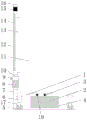
FIG. 1 is a schematic structural view of the present invention;
fig. 2 is a left side view structural diagram of the support plate of the present invention.
In the figure: the device comprises a supporting seat 1, a storage battery 2, a USB jack 3, a battery groove 4, a traveling wheel 5, an electric telescopic rod 6, a mounting plate 7, a bearing 8, a fastening screw 9, a limiting sleeve 10, a box body 11, a supporting plate 12, a connecting rod 13, a photocatalyst layer 14, a pull groove 15, a controller 16, a groove 17, a screw hole 18 and a charging port 19.
Detailed Description
The technical solutions in the embodiments of the present invention will be described clearly and completely with reference to the accompanying drawings in the embodiments of the present invention, and it is obvious that the described embodiments are only some embodiments of the present invention, not all embodiments. Based on the embodiments in the present invention, all other embodiments obtained by a person skilled in the art without creative work belong to the protection scope of the present invention.
The utility model discloses a supporting seat 1, battery 2, USB jack 3, battery jar 4, walking wheel 5, electric telescopic handle 6, mounting panel 7, bearing 8, fastening screw 9, stop collar 10, box 11, backup pad 12, connecting rod 13, photocatalyst layer 14, kerve 15, controller 16, recess 17, screw 18 and the 19 parts of charging mouth are the general standard or the part that technical staff in the field knows, its structure and principle all are that this technical staff all can learn the manual through the technique or learn through conventional experimental approach.
Referring to fig. 1-2, a multifunctional travel draw-bar box comprises a supporting seat 1 and a box body 11, wherein a groove 17 is formed around the bottom of the supporting seat 1, an electric telescopic rod 6 is fixedly connected to the top end of the inner cavity of the groove 17, a traveling wheel 5 is movably mounted at the bottom of the electric telescopic rod 6, so that people can conveniently move the draw-bar box, the electric telescopic rod 6 is contracted into the groove 17 through a controller 16 under the condition that the movement is not needed, the placing stability of the draw-bar box is ensured, a USB jack 3 is formed at the middle end of the top of the supporting seat 1, so that electric energy can be provided for a mobile phone without a power supply, the normal communication of people is ensured, great convenience is brought to the life of people, a battery groove 4 is formed at the lower end of the USB jack 3 in the inner cavity of the supporting seat 1, and a storage battery 2 is fixedly connected to the middle, meanwhile, a charging port 19 is formed in the top of the supporting seat 1 and on the left side of the USB jack 3, the charging port 19 can charge the storage battery 2, a mounting plate 7 is fixedly connected to the left end of the top of the supporting seat 1, a bearing 8 is fixedly connected to the top end of the mounting plate 7, a supporting plate 12 is movably connected to the inner surface of the bearing 8, the top end of the mounting plate 7 and the bottom of the supporting plate 12 are both cylindrical structures, a photocatalyst layer 14 is coated on the left side of the supporting plate 12 and can be used for sterilizing the surrounding environment, a pull groove 15 is formed in the upper end of the inner surface of the supporting plate 12, a controller 16 is fixedly connected to the rear end of the top of the supporting plate 12, a box body 11 is fixedly connected to the right side of the supporting plate 12 through a connecting rod 13, a limiting sleeve 10 is fixedly connected to the top end of the bearing, the supporting seat 1 can have the function of a stool, and great convenience is brought to the journey of people.
During the use, USB jack 3 has been seted up at the middle-end at supporting seat 1 top, can be for the cell-phone provides the electric energy under the condition that does not have the power, people's normal communication has been ensured, very big facility has been brought for people's life, simultaneously through mounting panel 7, bearing 8, stop collar 10, the effect of screw 18 and fastening screw 9, can make supporting seat 1 have the effect of bench, bring very big facility for people's journey, its simple structure of current draw-bar box has been solved, the function is single, can't satisfy the problem of people's demand that increases day by day, it is with the concrete mode that supporting seat 1 becomes the bench: not hard up fastening screw 9 earlier, then the level rotates box 11, thereby make box 11 leave (people alright sit at the top of supporting seat 1) from the top of supporting seat 1, then fastening screw 9 with between backup pad 12 and the stop collar 10 fixed can, top fixed connection at the recess 17 inner chamber has electric telescopic handle 6, and the bottom movable mounting at electric telescopic handle 6 has taken turns 5, can make things convenient for people to the removal of draw-bar box, and under the condition that does not need to remove, make electric telescopic handle 6 shrink into in the recess 17 through controller 16, the stability that this draw-bar box placed has been ensured, it establishes photocatalyst layer 14 to inlay in the left side of backup pad 12 simultaneously, can carry out the disinfection and sterilization to the surrounding environment.
In summary, the following steps: this multi-functional travel draw-bar box package, USB jack 3 has been seted up at the middle-end at supporting seat 1 top, can be for the cell-phone provides the electric energy under the condition that does not have the power, people's normal communication has been ensured, very big facility has been brought for people's life, simultaneously through mounting panel 7, bearing 8, stop collar 10, the effect of screw 18 and fastening screw 9, can make supporting seat 1 have the effect of bench, bring very big facility for people's journey, its simple structure of current draw-bar box has been solved, the function is single, can't satisfy the problem of people's demand growing increasingly.
Although embodiments of the present invention have been shown and described, it will be appreciated by those skilled in the art that changes, modifications, substitutions and alterations can be made in these embodiments without departing from the principles and spirit of the invention, the scope of which is defined in the appended claims and their equivalents.
Claims (4)
1. The utility model provides a multi-functional travel pull rod case, includes supporting seat (1) and box (11), its characterized in that: the supporting seat is characterized in that grooves (17) are formed in the periphery of the bottom of the supporting seat (1), an electric telescopic rod (6) is fixedly connected to the top end of an inner cavity of each groove (17), a walking wheel (5) is movably mounted at the bottom of the electric telescopic rod (6), a USB (universal serial bus) jack (3) is formed in the middle end of the top of the supporting seat (1), a mounting plate (7) is fixedly connected to the left end of the top of the supporting seat (1), a bearing (8) is fixedly connected to the top end of the mounting plate (7), a supporting plate (12) is movably connected to the inner surface of the bearing (8), a photocatalyst layer (14) is coated on the left side of the supporting plate (12), a box body (11) is fixedly connected to the right side of the supporting plate (12) through a connecting rod (13), a limiting sleeve (10) is fixedly connected to, and the inner cavity of the screw hole (18) is connected with a fastening screw (9) in a threaded manner.
2. The multi-functional travel draw-bar luggage of claim 1, wherein: the inner chamber of supporting seat (1) and the lower extreme that is located USB jack (3) have seted up battery jar (4), and well end fixedly connected with battery (2) of battery jar (4) inner chamber bottom, and charging mouth (19) have been seted up on the left side that the top of supporting seat (1) just is located USB jack (3) simultaneously.
3. The multi-functional travel draw-bar luggage of claim 1, wherein: the top end of the mounting plate (7) and the bottom of the support plate (12) are both cylindrical structures.
4. The multi-functional travel draw-bar luggage of claim 1, wherein: the upper end of the inner surface of the supporting plate (12) is provided with a pull groove (15), and the rear end of the top of the supporting plate (12) is fixedly connected with a controller (16).
Priority Applications (1)
| Application Number | Priority Date | Filing Date | Title |
|---|---|---|---|
| CN201922049413.XU CN211379931U (en) | 2019-11-23 | 2019-11-23 | Multifunctional travel draw-bar suitcase |
Applications Claiming Priority (1)
| Application Number | Priority Date | Filing Date | Title |
|---|---|---|---|
| CN201922049413.XU CN211379931U (en) | 2019-11-23 | 2019-11-23 | Multifunctional travel draw-bar suitcase |
Publications (1)
| Publication Number | Publication Date |
|---|---|
| CN211379931U true CN211379931U (en) | 2020-09-01 |
Family
ID=72220344
Family Applications (1)
| Application Number | Title | Priority Date | Filing Date |
|---|---|---|---|
| CN201922049413.XU Active CN211379931U (en) | 2019-11-23 | 2019-11-23 | Multifunctional travel draw-bar suitcase |
Country Status (1)
| Country | Link |
|---|---|
| CN (1) | CN211379931U (en) |
Cited By (1)
| Publication number | Priority date | Publication date | Assignee | Title |
|---|---|---|---|---|
| CN112293905A (en) * | 2020-10-21 | 2021-02-02 | 广东翔晟箱配科技有限公司 | Independently disinfection pull rod |
-
2019
- 2019-11-23 CN CN201922049413.XU patent/CN211379931U/en active Active
Cited By (1)
| Publication number | Priority date | Publication date | Assignee | Title |
|---|---|---|---|---|
| CN112293905A (en) * | 2020-10-21 | 2021-02-02 | 广东翔晟箱配科技有限公司 | Independently disinfection pull rod |
Similar Documents
| Publication | Publication Date | Title |
|---|---|---|
| CN211379931U (en) | Multifunctional travel draw-bar suitcase | |
| CN202456995U (en) | Multifunctional traveling bag | |
| CN202060204U (en) | Portable digital electronic charger bag | |
| CN205197265U (en) | Helping hand formula suitcase | |
| CN207855234U (en) | A kind of novel and multifunctional trolley case | |
| CN203237350U (en) | Electric vehicle | |
| CN208144649U (en) | A kind of luggage case convenient for charging | |
| CN205509596U (en) | Electric clipper charging seat | |
| CN108899449B (en) | Portable power box for electric vehicle | |
| CN205355921U (en) | Solar charging station with power generation facility | |
| CN204930628U (en) | A kind of Novel travelling case and bag | |
| CN203328176U (en) | Quakeproof pack sack applied to tourist project management | |
| CN203969532U (en) | A kind of Multifunctional travel suitcase | |
| CN203692752U (en) | Novel traveling suitcase | |
| CN205306229U (en) | Braces formula solar charging is precious | |
| CN201683230U (en) | Self-generating multifunctional electrically walking suitcase | |
| CN206164346U (en) | Power transfer ware | |
| CN219088588U (en) | Case with seat | |
| CN218500152U (en) | Draw-bar luggage with positioning and automatic following functions | |
| CN214016379U (en) | Foldable storage case | |
| CN103565091A (en) | Multifunctional field survival backpack | |
| CN212574430U (en) | Special knapsack of exploration | |
| CN201586087U (en) | Base of photocuring instrument | |
| CN204541091U (en) | A kind of Multifunction case and bag | |
| CN202536394U (en) | Chargeable mobile phone cover |
Legal Events
| Date | Code | Title | Description |
|---|---|---|---|
| GR01 | Patent grant | ||
| GR01 | Patent grant |