CN211366371U - Cloth coiling mechanism is used in fabrics processing - Google Patents
Cloth coiling mechanism is used in fabrics processing Download PDFInfo
- Publication number
- CN211366371U CN211366371U CN202020064366.6U CN202020064366U CN211366371U CN 211366371 U CN211366371 U CN 211366371U CN 202020064366 U CN202020064366 U CN 202020064366U CN 211366371 U CN211366371 U CN 211366371U
- Authority
- CN
- China
- Prior art keywords
- base
- fixed mounting
- cloth
- servo motor
- mounting
- Prior art date
- Legal status (The legal status is an assumption and is not a legal conclusion. Google has not performed a legal analysis and makes no representation as to the accuracy of the status listed.)
- Expired - Fee Related
Links
Images


Abstract
The utility model discloses a cloth coiling mechanism is used in fabrics processing, including base, coiling mechanism, elevating gear, blast apparatus and damping device, the recess has been seted up to the top one end of base, the one end fixed mounting of base has the coiling mechanism, square groove has been seted up at the middle part of base, fixed mounting has blast apparatus in the square groove of base, the top central authorities fixed mounting of base has elevating gear, elevating gear's bottom central authorities evenly rotate through the pivot and are connected with a plurality of cleaning rollers, the equal fixed mounting in one end of cleaning roller has drive gear, and one of them the one end of cleaning roller and first servo motor's output fixed connection, the drive gear overcoat has the drive belt, first servo motor passes through motor mounting bracket fixed mounting in one side of elevating gear, this cloth coiling mechanism is used in fabrics processing simple structure, this cloth coiling mechanism is used in fabrics processing, The operation is convenient, the cleaning work before the cloth rolling can be realized, and the overall practicability is higher.
Description
Technical Field
The utility model relates to a cloth rolling technical field specifically is a cloth coiling mechanism is used in fabrics processing.
Background
The general term of various fabrics. The fabric is a piece of fabric, the 'piece' originally is ancient Chinese measuring unit, 1 piece is 4 years, namely 13.2 meters, and ancient people are mostly used for measuring thin clothes. The fabric is called as the clothing material for making clothes, which is made of various materials such as terylene, cotton, hemp, silk and the like, and can be divided into the following parts in the weaving mode: the shuttle weaving cloth and the knitted cloth can be divided into two categories from the processing technology: grey cloth, bleached cloth, dyed cloth, printed cloth, colored woven cloth, mixed process cloth (such as printing on the colored woven cloth, composite cloth, flocked cloth, leather-like felt cloth) and the like.
However, the existing winding device does not have the cleaning function on the cloth, so that the cloth can be brought into impurities when being wound, the quality of the cloth is affected, troubles can be brought to a user, the cloth can be used only by cleaning, and therefore the cloth winding device for textile processing is provided.
SUMMERY OF THE UTILITY MODEL
An object of the utility model is to provide a cloth coiling mechanism is used in fabrics processing to solve the problem that proposes in the above-mentioned background art.
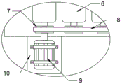
In order to achieve the above object, the utility model provides a following technical scheme: a cloth rolling device for textile processing, which comprises a base, a rolling device, a lifting device, a blowing device and a damping device, one end of the top of the base is provided with a groove, one end of the base is fixedly provided with a rolling device, a square groove is arranged in the middle of the base, a blowing device is fixedly arranged in the square groove of the base, the center of the top of the base is fixedly provided with a lifting device, the center of the bottom of the lifting device is uniformly and rotatably connected with a plurality of cleaning rollers through rotating shafts, one end of each cleaning roller is fixedly provided with a transmission gear, one end of one of the cleaning rollers is fixedly connected with the output end of the first servo motor, a transmission belt is sleeved outside the transmission gear, the first servo motor is fixedly installed on one side of the lifting device through a motor installation frame, and a damping device is fixedly installed at the bottom of the base.
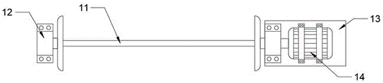
Preferably, the coiling mechanism includes wind-up roll, turning block, extension board and second servo motor, the equal fixed mounting in one end both sides of base has the turning block, the turning block rotates through the pivot and is connected with the wind-up roll, the one end of wind-up roll and second servo motor's output fixed connection, just second servo motor passes through extension board fixed mounting in one side of base.
Preferably, elevating gear includes mounting panel, installing support, cylinder and backup pad, the equal fixed mounting in both ends of mounting panel has the installing support, just the through-hole has all been seted up at the both ends of installing support, equal fixed mounting has the cylinder in the installing support, the output of cylinder all with the top fixed connection of backup pad, just backup pad sliding connection is in the through-hole at installing support both ends, the bottom fixed mounting of backup pad is at the top of base.
Preferably, the blowing device comprises a support frame, supporting springs, an air deflector, an air inlet pipe, a brush plate and a fan, the support frame is fixedly installed at the bottom of the square groove of the base, the supporting springs are fixedly installed at the top of the support frame, the air deflector is fixedly installed at the top of the supporting springs, a plurality of air outlets are uniformly formed in the top of the air deflector, the brush plate is fixedly installed at the top of the air deflector, a mounting hole is formed in the center of the bottom of the air deflector, the air inlet pipe is fixedly installed in the mounting hole of the air deflector, the air inlet pipe is fixedly connected with the output end of the fan through a connecting pipe, and the fan is fixedly installed at the bottom of the square groove of the base.
Preferably, damping device includes mount pad, damping spring, connecting key, support column, connecting rod, reinforcement otic placode and universal auto-lock wheel, the equal fixed mounting in bottom four corners of base has the mount pad, just the junction of mount pad and base is through reinforcing otic placode fixed connection, equal fixed mounting has damping spring in the mount pad, the equal fixed mounting in damping spring's bottom has the connecting key, just the bottom of connecting key and the top fixed connection of support column, through connecting rod fixed connection between the support column, the equal fixed mounting in bottom of support column has universal auto-lock wheel.
Compared with the prior art, the beneficial effects of the utility model are that: when the equipment needs to operate, cloth is put in from one end of the equipment, then the first servo motor drives the transmission gear and the transmission belt to rotate, thereby driving the cleaning roller to rotate to clean the upper surface of the cloth, the lifting device is convenient for the cleaning roller to be more attached to the surface of the cloth, the cleaning effect is increased, the blowing device arranged in the middle of the equipment cleans the lower surface of the cloth, and the supporting spring is arranged to match with the lifting device to integrally improve the fitting degree of the equipment to the cloth, so that the cleaning effect is improved, after the cleaning is good, by the coiling mechanism clean cloth rolling, in addition, damping device's existence is convenient to reduce the produced activity when equipment operation, this cloth coiling mechanism for fabrics processing simple structure, simple operation, can realize the cleaning before the cloth rolling, whole practicality is higher.
Drawings
FIG. 1 is a schematic view of the overall structure of the present invention;
FIG. 2 is a schematic view of a winding device;
FIG. 3 is a schematic view of the transmission connection;
FIG. 4 is a schematic view of a blowing device;
FIG. 5 is a schematic view of a shock absorbing device;
FIG. 6 is a schematic view of a portion of the lift apparatus;
FIG. 7 is a top view of the air deflector.
In the figure: 1. a base; 2. a winding device; 3. a lifting device; 4. a blowing device; 5. a damping device; 6. a cleaning roller; 7. a transmission gear; 8. a transmission belt; 9. a first servo motor; 10. a motor mounting bracket; 11. a wind-up roll; 12. rotating the block; 13. a support plate; 14. a second servo motor; 15. mounting a plate; 16. mounting a bracket; 17. a cylinder; 18. a support plate; 19. a support frame; 20. a support spring; 21. an air deflector; 22. an air inlet pipe; 23. brushing the board; 24. a fan; 25. a mounting seat; 26. a damping spring; 27. a connecting bond; 28. a support pillar; 29. a connecting rod; 30. reinforcing the ear plate; 31. universal auto-lock wheel.
Detailed Description
The technical solutions in the embodiments of the present invention will be described clearly and completely with reference to the accompanying drawings in the embodiments of the present invention, and it is obvious that the described embodiments are only some embodiments of the present invention, not all embodiments. Based on the embodiments in the present invention, all other embodiments obtained by a person skilled in the art without creative work belong to the protection scope of the present invention.
Referring to fig. 1-7, the present invention provides a technical solution: a cloth rolling device for textile processing comprises a base 1, a rolling device 2, a lifting device 3, a blowing device 4 and a damping device 5, wherein one end of the top of the base 1 is provided with a groove, one end of the base 1 is fixedly provided with the rolling device 2, the middle of the base 1 is provided with a square groove, the blowing device 4 is fixedly arranged in the square groove of the base 1, the lifting device 3 is fixedly arranged at the center of the top of the base 1, the center of the bottom of the lifting device 3 is uniformly and rotatably connected with a plurality of cleaning rollers 6 through rotating shafts, one end of each cleaning roller 6 is fixedly provided with a transmission gear 7, one end of one cleaning roller 6 is fixedly connected with the output end of a first servo motor 9, the transmission gear 7 is sleeved with a transmission belt 8, the first servo motor 9 is fixedly arranged on one side of the lifting device 3 through a motor mounting rack 10, and a damping device 5 is fixedly arranged at the bottom of the base 1.
The blowing device 4 comprises a support frame 19, a support spring 20, an air deflector 21, an air inlet pipe 22, a brush plate 23 and a fan 24, the support frame 19 is fixedly installed at the bottom of the square groove of the base 1, a plurality of support springs 20 are fixedly installed at the top of the support frame 19, the air deflector 21 is fixedly installed at the top of the support springs 20, a plurality of air outlets are uniformly arranged at the top of the air deflector 21, the brush plate 23 is fixedly installed at the top of the air deflector 21, a mounting hole is formed in the center of the bottom of the air deflector 21, the air inlet pipe 22 is fixedly installed at the mounting hole of the air deflector 21, the air inlet pipe 22 is fixedly connected with the output end of the fan 24 through a connecting pipe, the fan 24 is fixedly installed at the bottom of the square groove of the base 1, the fan 24 blows air to the air deflector 21 through the air penetrating holes of the brush plate 23 to cloth, and cleans the cloth by matching with a, the presence of the supporting spring 20 causes the cooperating lifting device 3 to operate.
The damping device 5 comprises a mounting seat 25, a damping spring 26, a connecting key 27, a supporting column 28, a connecting rod 29, a reinforcing lug plate 30 and a universal self-locking wheel 31, wherein the mounting seat 25 is fixedly mounted at the four corners of the bottom of the base 1, the connecting seat 25 is fixedly connected with the joint of the mounting seat 25 and the base 1 through the reinforcing lug plate 30, the damping spring 26 is fixedly mounted in the mounting seat 25, the connecting key 27 is fixedly mounted at the bottom of the damping spring 26, the bottom of the connecting key 27 is fixedly connected with the top of the supporting column 28, the supporting column 28 is fixedly connected through the connecting rod 29, the universal self-locking wheel 31 is fixedly mounted at the bottom of the supporting column 28, the vibration generated by the equipment is reduced by the matching of the mounting seat 25, the damping spring 26, the connecting key 27 and the supporting column 28, the connecting rod 29 and the reinforcing lug plate 30 play a role in reinforcing, and the stability of the equipment, the presence of the gimbaled self-locking wheels 31 allows the apparatus to move.
The working principle is as follows: when the equipment needs to operate, cloth is put into the equipment from one end of the equipment, then the first servo motor 9 drives the transmission gear 7 and the transmission belt 8 to rotate, and further drives the cleaning roller 6 to rotate to clean the upper surface of the cloth, the existence of the lifting device 3 facilitates the cleaning roller 6 to be more attached to the surface of the cloth, the cylinder 17 drives the mounting plate 15 to move up and down, so that the first servo motor 9 and the cleaning roller 6 move up and down simultaneously to increase the cleaning effect, the blowing device 4 arranged in the middle of the equipment cleans the lower surface of the cloth, the fan 24 blows air to the air guide plate 21 along the air inlet pipe 22, the air guide plate 21 is matched with the brush plate 23 to clean the lower surface of the cloth, the supporting spring 20 is arranged to be matched with the lifting device 3 to integrally improve the attachment degree of the equipment to the cloth, so that the cleaning effect is increased, after the cleaning is finished, the cleaned cloth is rolled up by the rolling device 2, second servo motor 14 drives wind-up roll 11 and rotates to carry out the rolling work, turning block 12 plays spacing and cooperation pivoted effect, in addition, damping device 5's existence is convenient to reduce the produced activity when equipment moves, damping spring 26, the cooperation of connector link 27 and support column 28 can be effectual the vibrations that reduce equipment operation produced, connecting rod 29 and reinforcing otic placode 30 are then the stability that has increased equipment, universal auto-lock wheel 31 is then the mobility that has increased equipment.
It is noted that, herein, relational terms such as first and second, and the like may be used solely to distinguish one entity or action from another entity or action without necessarily requiring or implying any actual such relationship or order between such entities or actions. Also, the terms "comprises," "comprising," or any other variation thereof, are intended to cover a non-exclusive inclusion, such that a process, method, article, or apparatus that comprises a list of elements does not include only those elements but may include other elements not expressly listed or inherent to such process, method, article, or apparatus.
Although embodiments of the present invention have been shown and described, it will be appreciated by those skilled in the art that changes, modifications, substitutions and alterations can be made in these embodiments without departing from the principles and spirit of the invention, the scope of which is defined in the appended claims and their equivalents.
Claims (5)
1. The utility model provides a fabric coiling mechanism is used in fabrics processing, includes base (1), coiling mechanism (2), elevating gear (3), blast apparatus (4) and damping device (5), its characterized in that: the cleaning device is characterized in that one end of the top of the base (1) is provided with a groove, one end of the base (1) is fixedly provided with a winding device (2), the middle of the base (1) is provided with a square groove, a blowing device (4) is fixedly arranged in the square groove of the base (1), the center of the top of the base (1) is fixedly provided with a lifting device (3), the center of the bottom of the lifting device (3) is uniformly and rotatably connected with a plurality of cleaning rollers (6) through a rotating shaft, one end of each cleaning roller (6) is fixedly provided with a transmission gear (7), one end of one cleaning roller (6) is fixedly connected with the output end of a first servo motor (9), the transmission gear (7) is sleeved with a transmission belt (8), and the first servo motor (9) is fixedly arranged on one side of the lifting device (3) through a motor mounting rack, and a damping device (5) is fixedly arranged at the bottom of the base (1).
2. The cloth rolling device for textile processing according to claim 1, characterized in that: coiling mechanism (2) include wind-up roll (11), turning block (12), extension board (13) and second servo motor (14), the equal fixed mounting in one end both sides of base (1) has turning block (12), turning block (12) rotate through the pivot and are connected with wind-up roll (11), the one end of wind-up roll (11) and the output fixed connection of second servo motor (14), just second servo motor (14) are through one side of extension board (13) fixed mounting at base (1).
3. The cloth rolling device for textile processing according to claim 1, characterized in that: elevating gear (3) include mounting panel (15), installing support (16), cylinder (17) and backup pad (18), the equal fixed mounting in both ends of mounting panel (15) has installing support (16), just the through-hole has all been seted up at the both ends of installing support (16), equal fixed mounting has cylinder (17) in installing support (16), the output of cylinder (17) all with the top fixed connection of backup pad (18), just backup pad (18) sliding connection is in the through-hole at installing support (16) both ends, the bottom fixed mounting of backup pad (18) is at the top of base (1).
4. The cloth rolling device for textile processing according to claim 1, characterized in that: the blowing device (4) comprises a support frame (19), a support spring (20), an air deflector (21), an air inlet pipe (22), a brush plate (23) and a fan (24), a supporting frame (19) is fixedly arranged at the bottom of the square groove of the base (1), a plurality of supporting springs (20) are fixedly arranged at the top of the supporting frame (19), the top of the supporting spring (20) is fixedly provided with an air deflector (21), a plurality of air outlets are uniformly arranged at the top of the air deflector (21), a brush plate (23) is fixedly arranged at the top of the air deflector (21), a mounting hole is arranged at the center of the bottom of the air deflector (21), an air inlet pipe (22) is fixedly arranged in the mounting hole of the air deflector (21), the air inlet pipe (22) is fixedly connected with the output end of the fan (24) through a connecting pipe, and the fan (24) is fixedly arranged at the bottom of the square groove of the base (1).
5. The cloth rolling device for textile processing according to claim 1, characterized in that: damping device (5) are including mount pad (25), damping spring (26), connection key (27), support column (28), connecting rod (29), reinforcement otic placode (30) and universal auto-lock wheel (31), the equal fixed mounting in bottom four corners of base (1) has mount pad (25), just mount pad (25) is through reinforcing otic placode (30) fixed connection with the junction of base (1), equal fixed mounting has damping spring (26) in mount pad (25), the equal fixed mounting in bottom of damping spring (26) has connection key (27), just the bottom of connection key (27) and the top fixed connection of support column (28), through connecting rod (29) fixed connection between support column (28), the equal fixed mounting in bottom of support column (28) has universal auto-lock wheel (31).
Priority Applications (1)
| Application Number | Priority Date | Filing Date | Title |
|---|---|---|---|
| CN202020064366.6U CN211366371U (en) | 2020-01-13 | 2020-01-13 | Cloth coiling mechanism is used in fabrics processing |
Applications Claiming Priority (1)
| Application Number | Priority Date | Filing Date | Title |
|---|---|---|---|
| CN202020064366.6U CN211366371U (en) | 2020-01-13 | 2020-01-13 | Cloth coiling mechanism is used in fabrics processing |
Publications (1)
| Publication Number | Publication Date |
|---|---|
| CN211366371U true CN211366371U (en) | 2020-08-28 |
Family
ID=72171753
Family Applications (1)
| Application Number | Title | Priority Date | Filing Date |
|---|---|---|---|
| CN202020064366.6U Expired - Fee Related CN211366371U (en) | 2020-01-13 | 2020-01-13 | Cloth coiling mechanism is used in fabrics processing |
Country Status (1)
| Country | Link |
|---|---|
| CN (1) | CN211366371U (en) |
Cited By (1)
| Publication number | Priority date | Publication date | Assignee | Title |
|---|---|---|---|---|
| CN115140611A (en) * | 2022-06-23 | 2022-10-04 | 上海君威钢绳索具股份有限公司 | Automatic winding device for steel wire rope |
-
2020
- 2020-01-13 CN CN202020064366.6U patent/CN211366371U/en not_active Expired - Fee Related
Cited By (1)
| Publication number | Priority date | Publication date | Assignee | Title |
|---|---|---|---|---|
| CN115140611A (en) * | 2022-06-23 | 2022-10-04 | 上海君威钢绳索具股份有限公司 | Automatic winding device for steel wire rope |
Similar Documents
| Publication | Publication Date | Title |
|---|---|---|
| CN211366371U (en) | Cloth coiling mechanism is used in fabrics processing | |
| CN213061335U (en) | Textile cleaning device | |
| CN210236636U (en) | Cloth leveling device for tailoring | |
| CN205871463U (en) | Weaving of collection dirt type is with stamp device of weaving | |
| CN219525769U (en) | Textile fabric rolling is with direction leveling device | |
| CN112575476B (en) | Padding equipment for tencel fabric dyeing and finishing | |
| CN216474138U (en) | Polyester knitted fabric dyeing device capable of improving dyeing rate | |
| CN216302819U (en) | Automatic change weaving machine weaving guide roller frame | |
| CN212603994U (en) | Equipment for textile cloth printing | |
| CN214527098U (en) | Cloth coiling mechanism for weaving equipment | |
| CN211734828U (en) | Cloth cutting device for textile machinery | |
| CN212049715U (en) | Cloth is coiling mechanism for weaving | |
| CN111926488A (en) | Textile fabric printing and dyeing equipment convenient to adjust and adjusting method thereof | |
| CN210458717U (en) | Cleaning device is used in cotton production | |
| CN112777261A (en) | Cloth is emptyd material feeding unit of seeing device off | |
| CN112411059A (en) | Surface fabric belt cleaning device is used in spinning machine processing | |
| CN112281287A (en) | Equipment for absorbing and treating textile dust of textile machine | |
| CN219260295U (en) | Polyester-nylon composite spinning device | |
| CN216466622U (en) | A compounding machine for mixing mulberry silk and goose down | |
| CN220266089U (en) | Cloth fuzzing machine | |
| CN214572789U (en) | Surface fabric leveling device for textile machinery | |
| CN220950376U (en) | Non-woven fabrics winding mechanism | |
| CN211665364U (en) | Cloth cleaning device is used in fabrics processing | |
| CN213972919U (en) | Spring inferior textile fabric drying equipment | |
| CN214328184U (en) | Textile fabric napping machine |
Legal Events
| Date | Code | Title | Description |
|---|---|---|---|
| GR01 | Patent grant | ||
| GR01 | Patent grant | ||
| CF01 | Termination of patent right due to non-payment of annual fee | ||
| CF01 | Termination of patent right due to non-payment of annual fee |
Granted publication date: 20200828 Termination date: 20210113 |