CN211734828U - Cloth cutting device for textile machinery - Google Patents
Cloth cutting device for textile machinery Download PDFInfo
- Publication number
- CN211734828U CN211734828U CN202020204592.XU CN202020204592U CN211734828U CN 211734828 U CN211734828 U CN 211734828U CN 202020204592 U CN202020204592 U CN 202020204592U CN 211734828 U CN211734828 U CN 211734828U
- Authority
- CN
- China
- Prior art keywords
- cutting
- box
- box body
- cloth
- cutting device
- Prior art date
- Legal status (The legal status is an assumption and is not a legal conclusion. Google has not performed a legal analysis and makes no representation as to the accuracy of the status listed.)
- Expired - Fee Related
Links
Images
Landscapes
- Treatment Of Fiber Materials (AREA)
Abstract
The utility model discloses a cloth cutting device for spinning machine relates to weaving technical field, which comprises a bracket, the transmission case is established at the support top, establish horizontal screw and driving motor in the transmission case, ball nut is established to the cover on the horizontal screw, ball nut below fixed connection hydraulic stem, the cutting case is established to the hydraulic stem bottom, the cutting case includes box, mount, nip roll and cutting knife, the nip roll is established to the box both sides, the nip roll both ends are rotated with the bearing block respectively and are connected, the bearing block is located the vertical spout of box lateral wall, establish the cutting knife in the box, the box peripheral hardware dust absorption mouth of the relative one side of cutting motor. The utility model discloses simple structure, reasonable in design, cutting device operates steadily, and the cutting of cloth is neat, removes follow-up secondary treatment from, in time collects the flock that the cutting produced, avoids the flock to be infected with the cloth, and labour saving and time saving has accelerated production efficiency, has improved product quality.
Description
Technical Field
The utility model belongs to the technical field of the textile technology and specifically relates to a cloth cutting device for spinning machine.
Background
Textile machinery is various mechanical equipment required for processing natural fibers or chemical fibers into textiles, although machinery for producing chemical fibers comprises various chemical machinery, the machinery is considered as an extension of the textile machinery at present, the machinery belongs to the broad sense of textile machinery, different processes required for processing different fibers such as cotton, hemp, silk, wool and the like into textiles are different, and some of the processes are completely different, so required machines are various and various, and the textile machinery is generally classified according to production processes and comprises the following steps: spinning equipment, weaving equipment, printing and dyeing equipment, finishing equipment, chemical fiber take out silk equipment, reeling equipment and non-woven fabrics equipment, wherein the cloth that is used for different functions need to be tailor as required, but traditional cutting machine for cloth crumples easily when the cloth is tailor, leads to the cloth cutting not enough to level, and the end of a thread that the cutting produced in addition also can not be cleared up well, has reduced the practicality of cutting machine.
SUMMERY OF THE UTILITY MODEL
In order to overcome the above-mentioned defect that exists among the prior art, the utility model provides a cloth cutting device for textile machinery.
The utility model provides a technical scheme that its technical problem adopted is: a cloth cutting device for textile machinery comprises a support, wherein the support is positioned on two sides of a material conveying roller, the support is vertically arranged, a transmission case is arranged at the top of the support, a horizontal screw and a driving motor are arranged in the transmission case, two ends of the horizontal screw are respectively in rotating connection with output ends of the transmission case and the driving motor, a ball nut is sleeved on the horizontal screw, a hydraulic rod is fixedly connected below the ball nut, a slot is formed in the bottom of the transmission case, the hydraulic rod is arranged in the slot in a sliding manner, limiting cushion blocks are arranged at two ends of the slot, a guide rod is arranged in the middle of the support, two ends of the guide rod are respectively fixedly connected with the support and are parallel to the horizontal screw, a sliding block is fixedly connected on the hydraulic rod and is in sliding connection with the guide rod, a cutting case is arranged at the bottom of the hydraulic rod and comprises a case body, a, the utility model discloses a pneumatic material pressing device, including fixing frame, bearing block, telescopic link, spring, cutting motor, air pump, air suction pipe, air pump, mounting bracket and hydraulic stem fixed connection, the box is established to the fixing frame below, the bottom half is opened, the nip roll is established to the box both sides, the nip roll both ends rotate with the bearing block respectively and are connected, the bearing block is arranged in the vertical spout of box lateral wall, establish the telescopic link between bearing block top and box top, the spring is established to the cover on the telescopic link, the vertical cutting knife that sets up in box middle part, the axis direction of the perpendicular nip roll of cutting knife, the cutting motor outside the cutting motor of cutting motor through the pivot connection box.
Foretell a fabric cutting device for spinning machine, the bottom of the box is equipped with the brush.
Foretell a cloth cutting device for spinning machine, dust absorption mouth department establishes the filter screen.
The beneficial effects of the utility model are that, the utility model discloses simple structure, reasonable in design, cutting device operates steadily, and the nip roll is located the front and back both sides of cutting knife respectively, avoids the cloth to take place to rock at the in-process of cutting and makes the cutting of cloth uneven, produces the waste material, removes follow-up secondary treatment process from, and the cutting knife is located the box simultaneously, and the box inserts the air pump, in time collects the flock that produces the cutting, avoids the flock to be infected with the cloth, and labour saving and time saving has accelerated production efficiency, has improved product quality.
Drawings
The present invention will be further explained with reference to the drawings and examples.
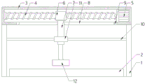
Fig. 1 is a schematic structural view of the present invention;
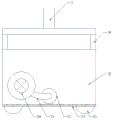
FIG. 2 is a schematic structural view of the cutting box of the present invention;
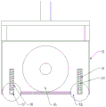
FIG. 3 is a cross-sectional view of the cutting box of the present invention;
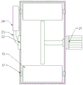
fig. 4 is a top view of the cutting box of the present invention.
In the figure, 1, a support, 2, a material conveying roller, 3, a transmission case, 4, a horizontal screw rod, 5, a driving motor, 6, a ball nut, 7, a hydraulic rod, 8, a groove, 9, a limit cushion block, 10, a guide rod, 11, a sliding block, 12, a cutting case, 13, a case body, 14, a fixed frame, 15, a material pressing roller, 16, a cutting knife, 17, a bearing block, 18, a vertical sliding groove, 19, an expansion rod, 20, a spring, 21, a cutting motor, 22, a dust suction port, 23, a suction pipe, 24, an air pump and 25 are arranged.
Detailed Description
In order to more clearly illustrate the technical solution of the present invention, the following provides a further description of the present invention with reference to the accompanying drawings, and obviously, the following described drawings are only one embodiment of the present invention, and for those skilled in the art, other embodiments can be obtained according to the drawings and the embodiment without any creative work, and all belong to the protection scope of the present invention.
The utility model provides a cloth cutting device for textile machinery, includes support 1, its characterized in that: the support 1 is positioned on two sides of a material conveying roller 2, the support 1 is vertically arranged, a transmission case 3 is arranged at the top of the support 1, a horizontal screw 4 and a driving motor 5 are arranged in the transmission case 3, two ends of the horizontal screw 4 are respectively connected with the output ends of the transmission case 3 and the driving motor 5 in a rotating manner, a ball nut 6 is sleeved on the horizontal screw 4, a hydraulic rod 7 is fixedly connected below the ball nut 6, a slot 8 is arranged at the bottom of the transmission case 3, the hydraulic rod 7 is arranged in the slot 8 in a sliding manner, limiting cushion blocks 9 are arranged at two ends of the slot 8, a guide rod 10 is arranged in the middle of the support 1, two ends of the guide rod 10 are respectively fixedly connected with the support 1, the guide rod 10 is parallel to the horizontal screw 4, a sliding block 11 is fixedly connected on the hydraulic rod 7, the sliding block 11 is connected with the guide rod 10 in a sliding manner, so as to increase the stability of, the cutting box 12 comprises a box body 13, a fixing frame 14, a nip roll 15 and a cutting knife 16, the fixing frame 14 is fixedly connected with a hydraulic rod 7, the box body 13 is arranged below the fixing frame 14, the bottom of the box body 13 is opened, the nip roll 15 is arranged on two sides of the box body 13, two ends of the nip roll 15 are respectively rotatably connected with a bearing block 17, the bearing block 17 is positioned in a vertical chute 18 on the side wall of the box body 13, an expansion link 19 is arranged between the top of the bearing block 17 and the top of the box body 13, a spring 20 is sleeved on the expansion link 19, the cutting knife 16 is vertically arranged in the middle of the box body 13, the cutting knife 16 is perpendicular to the axial direction of the nip roll 15, the cutting knife 16 is connected with a cutting motor 21 outside the side wall of the box body 13 through a rotating shaft, a dust suction opening 22 is arranged outside the box body 13 on one side opposite to, prevent that the cloth from taking place the displacement when cutting, air pump 24 and dust absorption mouth 22 collect the piece that produces when cutting the cloth, avoid dropping on the cloth and carry out the secondary clearance.
In detail, a brush 25 is arranged at the bottom of the box body 13 to prevent the cut flocks from being stained with cloth, and a filter screen is arranged at the dust suction port 22.
The above embodiments are only exemplary embodiments of the present invention, and are not intended to limit the present invention, and the protection scope of the present invention is defined by the claims. Various modifications and equivalents of the invention can be made by those skilled in the art within the spirit and scope of the invention, and such modifications and equivalents should also be considered as falling within the scope of the invention.
Claims (3)
1. The utility model provides a cloth cutting device for textile machinery, includes support (1), its characterized in that: the device is characterized in that the support (1) is located on two sides of the material conveying roller (2), the transmission case (3) is vertically arranged on the support (1) and arranged at the top of the support (1), a horizontal lead screw (4) and a driving motor (5) are arranged in the transmission case (3), two ends of the horizontal lead screw (4) are respectively connected with the output ends of the transmission case (3) and the driving motor (5) in a rotating mode, a ball nut (6) is sleeved on the horizontal lead screw (4), a hydraulic rod (7) is fixedly connected below the ball nut (6), a notch (8) is formed in the bottom of the transmission case (3), the hydraulic rod (7) is arranged in the notch (8) in a sliding mode, limiting cushion blocks (9) are arranged at two ends of the notch (8), a guide rod (10) is arranged in the middle of the support (1), two ends of the guide rod (10) are respectively and fixedly connected with the support (1) and the, the cutting device is characterized in that a sliding block (11) is fixedly connected to the hydraulic rod (7), the sliding block (11) is slidably connected with the guide rod (10), a cutting box (12) is arranged at the bottom of the hydraulic rod (7), the cutting box (12) comprises a box body (13), a fixing frame (14), a material pressing roller (15) and a cutting knife (16), the fixing frame (14) is fixedly connected with the hydraulic rod (7), the box body (13) is arranged below the fixing frame (14), the bottom of the box body (13) is opened, the material pressing roller (15) is arranged on two sides of the box body (13), two ends of the material pressing roller (15) are respectively rotatably connected with a bearing block (17), the bearing block (17) is positioned in a vertical sliding groove (18) in the side wall of the box body (13), a telescopic rod (19) is arranged between the top of the bearing block (17) and the top of the box body (13), a spring (20) is sleeved on the telescopic rod (19, the cutting device is characterized in that the cutting knife (16) is perpendicular to the axial direction of the nip roll (15), the cutting knife (16) is connected with a cutting motor (21) outside the side wall of the box body (13) through a rotating shaft, a dust suction opening (22) is formed in the box body (13) on one side, opposite to the cutting motor (21), of the cutting motor (21), and the dust suction opening (22) is connected with an air pump (24) through an air suction pipe (23).
2. Cloth cutting device according to claim 1, characterised in that the bottom of the box (13) is provided with brushes (25).
3. Cloth cutting device according to claim 1, characterised in that a filter screen is arranged at the suction opening (22).
Priority Applications (1)
| Application Number | Priority Date | Filing Date | Title |
|---|---|---|---|
| CN202020204592.XU CN211734828U (en) | 2020-02-25 | 2020-02-25 | Cloth cutting device for textile machinery |
Applications Claiming Priority (1)
| Application Number | Priority Date | Filing Date | Title |
|---|---|---|---|
| CN202020204592.XU CN211734828U (en) | 2020-02-25 | 2020-02-25 | Cloth cutting device for textile machinery |
Publications (1)
| Publication Number | Publication Date |
|---|---|
| CN211734828U true CN211734828U (en) | 2020-10-23 |
Family
ID=72877431
Family Applications (1)
| Application Number | Title | Priority Date | Filing Date |
|---|---|---|---|
| CN202020204592.XU Expired - Fee Related CN211734828U (en) | 2020-02-25 | 2020-02-25 | Cloth cutting device for textile machinery |
Country Status (1)
| Country | Link |
|---|---|
| CN (1) | CN211734828U (en) |
Cited By (1)
| Publication number | Priority date | Publication date | Assignee | Title |
|---|---|---|---|---|
| CN113882133A (en) * | 2021-10-29 | 2022-01-04 | 滁州市大振户外旅游用品有限公司 | Rain cloth cutting device |
-
2020
- 2020-02-25 CN CN202020204592.XU patent/CN211734828U/en not_active Expired - Fee Related
Cited By (2)
| Publication number | Priority date | Publication date | Assignee | Title |
|---|---|---|---|---|
| CN113882133A (en) * | 2021-10-29 | 2022-01-04 | 滁州市大振户外旅游用品有限公司 | Rain cloth cutting device |
| CN113882133B (en) * | 2021-10-29 | 2022-07-29 | 滁州市大振户外旅游用品有限公司 | Device is tailor to waterproof cloth |
Similar Documents
| Publication | Publication Date | Title |
|---|---|---|
| CN210368097U (en) | Carding device for spinning thread layer | |
| CN211734828U (en) | Cloth cutting device for textile machinery | |
| CN211284727U (en) | Dust removal device for processing yak wool yarns | |
| CN210368046U (en) | Weaving machine vibration damping mount for weaving yarn | |
| CN207176294U (en) | A kind of new carding machine with dust suction and receipts cloth efficiency high | |
| CN216585362U (en) | A comb and parallel cotton fibers prior to spinning device | |
| CN215593283U (en) | Novel spinning frame | |
| CN212798936U (en) | Multifunctional driving roller with wide application range for textile machinery | |
| CN214300937U (en) | Fluff removing device for textile fabric surface | |
| CN213507726U (en) | Textile product cleaning device | |
| CN210481782U (en) | Warp knitting cloth napping machine | |
| CN210546788U (en) | Weaving equipment dust collector | |
| CN209759657U (en) | carding machine for covering yarn | |
| CN211112398U (en) | Automatic tensile drawing frame | |
| CN214422821U (en) | Winding device for textile machine | |
| CN211036509U (en) | Cloth cutting device | |
| CN214655425U (en) | Novel duplex cashmere carding machine | |
| CN216404656U (en) | Efficient cone winder of yarn cleaning for textile engineering | |
| CN221218245U (en) | Knitted fabric cutting device | |
| CN216838379U (en) | Yarn cleaning device is used in weaving | |
| CN212594621U (en) | A dust collecting equipment for carding machine | |
| CN218090248U (en) | Textile fabric cleaning equipment | |
| CN219363903U (en) | Built-in dust collection type carding machine for cotton yarn spinning | |
| CN215628905U (en) | Two-sided dust collector of weaving machine | |
| CN214881989U (en) | Dust cage air suction assembly on bullet cleaning machine |
Legal Events
| Date | Code | Title | Description |
|---|---|---|---|
| GR01 | Patent grant | ||
| GR01 | Patent grant | ||
| CF01 | Termination of patent right due to non-payment of annual fee |
Granted publication date: 20201023 Termination date: 20210225 |
|
| CF01 | Termination of patent right due to non-payment of annual fee |