CN211334340U - Equal-diameter three-way injection mold - Google Patents
Equal-diameter three-way injection mold Download PDFInfo
- Publication number
- CN211334340U CN211334340U CN201921832845.1U CN201921832845U CN211334340U CN 211334340 U CN211334340 U CN 211334340U CN 201921832845 U CN201921832845 U CN 201921832845U CN 211334340 U CN211334340 U CN 211334340U
- Authority
- CN
- China
- Prior art keywords
- fixedly connected
- threaded rod
- shaped plate
- injection mold
- pipe
- Prior art date
- Legal status (The legal status is an assumption and is not a legal conclusion. Google has not performed a legal analysis and makes no representation as to the accuracy of the status listed.)
- Expired - Fee Related
Links
Images


Landscapes
- Moulds For Moulding Plastics Or The Like (AREA)
Abstract
The utility model discloses an isometric tee bend injection mold, the camera includes a supporting plate, the top fixedly connected with U template of backup pad, the bottom fixedly connected with motor on U template right side, the left end of motor shaft runs through to the inner chamber and the fixedly connected with threaded rod of U template, the left end of threaded rod passes through bearing and the left bottom swing joint of U template inner chamber, the surperficial threaded bush of threaded rod is equipped with the fly leaf, the front side and the equal fixedly connected with slide bar in rear side of U template inner chamber right side bottom, the left end of slide bar run through the fly leaf and with the left bottom fixed connection of U template inner chamber, fly leaf and slide bar sliding connection. The utility model provides a cooling rate of current tee bend injection mold in the mould die cavity after the completion of moulding plastics is slower, leads to the shaping of mould body slow to inconvenient follow mould after the shaping takes off, seriously delays the time of production and processing, has reduced production efficiency's problem.
Description
Technical Field
The utility model relates to an equal diameter tee bend injection mold technical field specifically is an equal diameter tee bend injection mold.
Background
In recent years, along with the economic soaring of China, plastic molding processing machinery and a molding die are developed rapidly, efficiently, automatically, large, miniature, precise and long-life, the proportion of the die occupying in the whole die industry is getting larger and larger, the large, complex, precise, efficient and long-life die in China is a new step, a plurality of types of dies can replace imported dies, the die technology is popularized and applied quickly and obtains good effect, rapid molding manufacturing technology and equipment are developed sufficiently and begin to enter a practical popularization stage, new generation manufacturing technology such as high-speed milling is valued and begins to be applied by people, the injection die is used for producing a three-way pipe, but the cooling speed in a die cavity of the existing three-way injection die after injection is completed is slow, so that the die body is molded slowly and is inconvenient to take off from the die after molding, the production and processing time is seriously prolonged, and the production efficiency is reduced.
SUMMERY OF THE UTILITY MODEL
An object of the utility model is to provide an isometric tee bend injection mold possesses the advantage that cooling rate is fast and convenient follow mould after the shaping takes off, and it is slower to have solved the cooling rate of current tee bend injection mold in the mould die cavity after the completion of moulding plastics, leads to mould body shaping slow to inconvenient follow the mould after the shaping and take off, seriously delay the time of production and processing, reduced production efficiency's problem.
In order to achieve the above object, the utility model provides a following technical scheme: an equal-diameter three-way injection mold comprises a supporting plate, wherein a U-shaped plate is fixedly connected to the top of the supporting plate, a motor is fixedly connected to the bottom of the right side of the U-shaped plate, the left end of a motor rotating shaft penetrates through an inner cavity of the U-shaped plate and is fixedly connected with a threaded rod, the left end of the threaded rod is movably connected with the left bottom of the inner cavity of the U-shaped plate through a bearing, a movable plate is sleeved on the surface of the threaded rod in a threaded manner, slide rods are fixedly connected to the front side and the rear side of the right bottom of the inner cavity of the U-shaped plate, the left end of each slide rod penetrates through the movable plate and is fixedly connected with the left bottom of the inner cavity of the U-shaped plate, the movable plate is slidably connected with the slide rods, a lower mold is fixedly connected to the top, the top of the supporting plate is provided with a groove, the bottom of the supporting plate is provided with a drain hole, the top of the drain hole is communicated with the bottom of an inner cavity of the groove, the bottom of the supporting plate is fixedly connected with a shell, the bottom of the shell is fixedly connected with a refrigerator, the inner cavity of the shell is provided with a cooling bent pipe, two ends of the cooling bent pipe penetrate through the shell and are fixedly communicated with the refrigerator, the bottom of the left side of the inner cavity of the shell is fixedly connected with a temperature sensor, the bottom of the left side of the U-shaped plate is fixedly connected with a water pump through a support, the bottom of a water inlet pipe of the water pump is fixedly communicated with a first conveying pipe, one end of the first conveying pipe, far away from the water pump, is fixedly communicated with the bottom of the left side, the four corners of the bottom of the supporting plate are fixedly connected with supporting legs.
Preferably, the front surface of the shell is fixedly connected with a liquid level window, and the front surface of the liquid level window is sprayed with scale marks.
Preferably, the right side fixedly connected with controller on the U template front, the controller respectively with motor, electric telescopic handle, refrigerator, temperature sensor and water pump electric connection.
Preferably, the bottom of the right side of the shell is fixedly communicated with a sewage discharge pipe, and a valve is arranged on the surface of the sewage discharge pipe.
Preferably, the bottom on the right side of the U-shaped plate is provided with a through hole matched with the motor rotating shaft, and the diameter of the motor rotating shaft is smaller than that of the through hole.
Preferably, a bearing is arranged between the threaded rod and the U-shaped plate, and the bearing is sleeved on the surface of the threaded rod.
Compared with the prior art, the beneficial effects of the utility model are as follows:
1. the utility model discloses a backup pad, the U template, including a motor, an end cap, a controller, and a cover plate, the threaded rod, the fly leaf, the slide bar, the bed die, electric telescopic handle, go up the mould, the inlet pipe, a groove, the wash port, a housing, the refrigerator, the cooling return bend, a weighing sensor and a water pump, first conveyer pipe, the second conveyer pipe, gondola water faucet and landing leg continue to cooperate, possess the advantage that cooling rate is fast and convenient to take off from the mould after the shaping, it is slower to have solved the cooling rate of current tee bend injection mold mould in the completion back mould die cavity of moulding plastics, it is slow to lead to mould body shaping, and inconvenient taking off from the mould after the shaping, seriously delay the time of production and processing.
2. The utility model discloses a set up the slide bar, the movement track to the fly leaf is fixed, prevent that the rotation of threaded rod from driving the fly leaf and rotating, through setting up liquid level window and scale mark, be convenient for observe the water level in the casing, carry out the water injection toward the casing in through recess and wash port, through setting up blow off pipe and valve, in time get rid of sewage and mud in the casing, through setting up the through-hole, do not receive the influence pivoted that the U template rotated more smoothly when making the motor shaft rotate, through setting up the bearing, it is fixed to support the threaded rod, do not receive the influence of U template when making the threaded rod rotate.
Drawings
FIG. 1 is a schematic structural view of the present invention;
FIG. 2 is a schematic front view of the present invention;
FIG. 3 is a schematic top view of the connection between the U-shaped plate and the sliding rod of the present invention;
fig. 4 is a schematic top view of the cooling elbow and frame connection of the present invention.
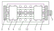
In the figure: the device comprises a support plate 1, a U-shaped plate 2, a motor 3, a threaded rod 4, a movable plate 5, a sliding rod 6, a lower die 7, an electric telescopic rod 8, an upper die 9, a feeding pipe 10, a groove 11, a drain hole 12, a shell 13, a refrigerator 14, a cooling bent pipe 15, a temperature sensor 16, a water pump 17, a first delivery pipe 18, a second delivery pipe 19, a shower head 20, support legs 21 and a controller 22.
Detailed Description
The technical solutions in the embodiments of the present invention will be described clearly and completely with reference to the accompanying drawings in the embodiments of the present invention, and it is obvious that the described embodiments are only some embodiments of the present invention, not all embodiments. Based on the embodiments in the present invention, all other embodiments obtained by a person skilled in the art without creative work belong to the protection scope of the present invention.
In the description of the present invention, it should be noted that the terms "upper", "lower", "inner", "outer", "front end", "rear end", "both ends", "one end", "the other end", and the like indicate orientations or positional relationships based on the orientations or positional relationships shown in the drawings, and are only for convenience of description and simplification of description, but do not indicate or imply that the device or element to be referred must have a specific orientation, be constructed in a specific orientation, and be operated, and thus, should not be construed as limiting the present invention. Furthermore, the terms "first" and "second" are used for descriptive purposes only and are not to be construed as indicating or implying relative importance.
In the description of the present invention, it is to be noted that, unless otherwise explicitly specified or limited, the terms "mounted", "provided", "connected", and the like are to be construed broadly, such as "connected", which may be fixedly connected, detachably connected, or integrally connected; can be mechanically or electrically connected; they may be connected directly or indirectly through intervening media, or they may be interconnected between two elements. The specific meaning of the above terms in the present invention can be understood in specific cases to those skilled in the art.
The utility model discloses a backup pad 1, U type board 2, motor 3, threaded rod 4, fly leaf 5, slide bar 6, bed die 7, electric telescopic handle 8, go up mould 9, inlet pipe 10, recess 11, wash port 12, casing 13, refrigerator 14, cooling return bend 15, temperature sensor 16, water pump 17, first conveyer pipe 18, second conveyer pipe 19, gondola water faucet 20, landing leg 21 and controller 22 part are general standard or the part that technical staff in the field knows, its structure and principle all are that this technical staff all can learn through the technical manual or learn through conventional experimental method.
Referring to fig. 1-4, an equal-diameter three-way injection mold comprises a support plate 1, a U-shaped plate 2 is fixedly connected to the top of the support plate 1, a motor 3 is fixedly connected to the bottom of the right side of the U-shaped plate 2, the left end of the rotating shaft of the motor 3 penetrates through the inner cavity of the U-shaped plate 2 and is fixedly connected with a threaded rod 4, the left end of the threaded rod 4 is movably connected with the bottom of the left side of the inner cavity of the U-shaped plate 2 through a bearing, a movable plate 5 is sleeved on the surface of the threaded rod 4 in a threaded manner, slide rods 6 are fixedly connected to the front side and the rear side of the right bottom of the inner cavity of the U-shaped plate 2, the left end of the slide rod 6 penetrates through the movable plate 5 and is fixedly connected with the bottom of the left side of the inner cavity of the U-shaped plate 2, the right side of the upper die 9 is fixedly communicated with a feeding pipe 10, the top of the supporting plate 1 is provided with a groove 11, the bottom of the supporting plate 1 is provided with a drain hole 12, the top of the drain hole 12 is communicated with the bottom of an inner cavity of the groove 11, the bottom of the supporting plate 1 is fixedly connected with a shell 13, the bottom of the shell 13 is fixedly connected with a refrigerator 14, the inner cavity of the shell 13 is provided with a cooling bent pipe 15, two ends of the cooling bent pipe 15 penetrate through the shell 13 and are fixedly communicated with the refrigerator 14, the left bottom of the inner cavity of the shell 13 is fixedly connected with a temperature sensor 16, the left bottom of the U-shaped plate 2 is fixedly connected with a water pump 17 through a bracket, the bottom of a water inlet pipe of the water pump 17 is fixedly communicated with a first conveying pipe 18, one end of the first conveying pipe 18, the bottom of the second conveying pipe 19 is fixedly communicated with a shower head 20, four corners of the bottom of the supporting plate 1 are fixedly connected with supporting legs 21, the movement track of the movable plate 5 is fixed by arranging a slide rod 6, the movable plate 5 is prevented from being driven to rotate by the rotation of the threaded rod 4, the front of the shell 13 is fixedly connected with a liquid level window, the front of the liquid level window is sprayed with scale marks, the water level in the shell 13 is convenient to observe by arranging the liquid level window and the scale marks, water is injected into the shell 13 through the groove 11 and the drain hole 12, the right side of the front of the U-shaped plate 2 is fixedly connected with a controller 22, the controller 22 is respectively and electrically connected with the motor 3, the electric telescopic rod 8, the refrigerator 14, the temperature sensor 16 and the water pump 17, the bottom of the right side of the shell 13 is fixedly communicated with a drain pipe, the surface of the drain pipe is, the bottom of the right side of the U-shaped plate 2 is provided with a through hole matched with a rotating shaft of the motor 3, the diameter of the rotating shaft of the motor 3 is smaller than that of the through hole, the rotating shaft of the motor 3 can rotate more smoothly without being influenced by the U-shaped plate 2 by the through hole, a bearing is arranged between the threaded rod 4 and the U-shaped plate 2 and sleeved on the surface of the threaded rod 4, the threaded rod 4 is supported and fixed by the bearing, the threaded rod 4 can rotate without being influenced by the U-shaped plate 2 by the support plate 1, the U-shaped plate 2, the motor 3, the threaded rod 4, the movable plate 5, the slide rod 6, the lower die 7, the electric telescopic rod 8, the upper die 9, the feeding pipe 10, the groove 11, the drain hole 12, the shell 13, the refrigerator 14, the cooling bent pipe 15, the temperature sensor 16, the water pump 17, the first conveying, possess the advantage that cooling rate is fast and convenient follow mould after the shaping takes off, it is slower to have solved the cooling rate of current tee bend injection mold in the mould die cavity after the completion of moulding plastics, leads to the shaping of mould body to inconvenient follow the mould after the shaping to take off, the time of production and processing is seriously postponed, has reduced production efficiency's problem.
When the injection molding machine is used, the controller 22 controls the operation of the motor rotating shaft, the rotation of the motor 3 rotating shaft drives the rotation of the threaded rod 4, the rotation of the threaded rod 4 drives the movable plate 5 to move towards the middle, the movable plate 5 moves towards the middle to tightly butt joint the two lower dies 7, the controller 22 controls the extension of the electric telescopic rod 8, the extension of the electric telescopic rod 8 drives the upper die 9 to be precisely butt joint with the two lower dies 7, so that a complete equal-diameter three-way injection mold is formed, injection molding liquid is injected into the mold through the feeding pipe 10, after the injection molding is completed, the controller 22 controls the operation of the refrigerator 14 and the water pump 17, the operation of the refrigerator 14 cools and cools water in the shell 13 through the cooling elbow pipe 15, the operation of the water pump 17 sprays the cooled and cooled water from the shower head through the first conveying pipe 18, the water pump 17 and the second conveying pipe 19 in sequence, the water after the temperature of the die is reduced is collected through the groove 11 and enters the shell 13 from the drain hole 12 for cooling and temperature reduction, so that the die is cooled rapidly and circularly, when the temperature sensor 16 detects that the temperature of the water in the shell 13 is lower than the set lowest temperature, information is fed back to the controller, the controller 22 controls the refrigerator 14 to be closed, along with the process of cooling the die, the temperature of the water in the shell 13 is gradually increased, when the temperature sensor 16 detects that the temperature of the water in the shell 13 is higher than the set highest temperature, the information is fed back to the controller, the controller 22 controls the refrigerator 14 to run, when the formed equal-diameter tee joint needs to be taken out, the controller 22 controls the contraction of the electric telescopic rod 8 to drive the upper die 9 to move upwards, the upper die 9 is separated from the formed equal-diameter tee joint, the controller 22 controls the reverse rotation of the rotating shaft of the motor 3, and the reverse rotation of the rotating shaft of the motor, the reverse rotation of the threaded rod 4 drives the movable plate 5 to move towards two sides, one lower die 7 is separated from the formed equal-diameter tee joint, and then the formed equal-diameter tee joint is taken down from the other lower die 7.
In summary, the following steps: this isodiametric tee bend injection mold, through backup pad 1, U template 2, motor 3, threaded rod 4, fly leaf 5, slide bar 6, bed die 7, electric telescopic handle 8, go up mould 9, inlet pipe 10, recess 11, wash port 12, casing 13, refrigerator 14, cooling return bend 15, temperature sensor 16, water pump 17, first conveyer pipe 18, second conveyer pipe 19, gondola water faucet 20 and landing leg 21 go forward the cooperation, it is slower to have solved the cooling rate of current tee bend injection mold in the mould die cavity after the completion of moulding plastics, lead to the shaping of mould body to slow, and inconvenient taking off from the mould after the shaping, seriously delay the time of production and processing, the problem of production efficiency has been reduced.
Although embodiments of the present invention have been shown and described, it will be appreciated by those skilled in the art that changes, modifications, substitutions and alterations can be made in these embodiments without departing from the principles and spirit of the invention, the scope of which is defined in the appended claims and their equivalents.
Claims (6)
1. The utility model provides an equal-diameter tee injection mold, includes backup pad (1), its characterized in that: the top of the supporting plate (1) is fixedly connected with a U-shaped plate (2), the bottom on the right side of the U-shaped plate (2) is fixedly connected with a motor (3), the left end of a rotating shaft of the motor (3) penetrates through an inner cavity of the U-shaped plate (2) and is fixedly connected with a threaded rod (4), the left end of the threaded rod (4) is movably connected with the left bottom of the inner cavity of the U-shaped plate (2) through a bearing, a movable plate (5) is sleeved on the surface of the threaded rod (4), slide rods (6) are fixedly connected with the front side and the rear side of the right bottom of the inner cavity of the U-shaped plate (2), the left end of each slide rod (6) penetrates through the movable plate (5) and is fixedly connected with the left bottom of the inner cavity of the U-shaped plate (2), the movable plate (5) is slidably connected with the slide rods (6), the top of the movable plate (, the bottom of the electric telescopic rod (8) is fixedly connected with an upper die (9), the right side of the upper die (9) is fixedly communicated with a feeding pipe (10), the top of the supporting plate (1) is provided with a groove (11), the bottom of the supporting plate (1) is provided with a drain hole (12), the top of the drain hole (12) is communicated with the bottom of an inner cavity of the groove (11), the bottom of the supporting plate (1) is fixedly connected with a shell (13), the bottom of the shell (13) is fixedly connected with a refrigerator (14), an inner cavity of the shell (13) is provided with a cooling bent pipe (15), two ends of the cooling bent pipe (15) penetrate through the shell (13) and are fixedly communicated with the refrigerator (14), the left bottom of the inner cavity of the shell (13) is fixedly connected with a temperature sensor (16), and the left bottom of the U-shaped plate (, the fixed intercommunication in bottom of water pump (17) inlet tube has first conveyer pipe (18), the fixed intercommunication in one end and the left bottom of casing (13) of water pump (17) are kept away from in first conveyer pipe (18), the one end of water pump (17) outlet pipe runs through to the inner chamber of U template (2) and fixed intercommunication has second conveyer pipe (19), the fixed intercommunication in bottom of second conveyer pipe (19) has gondola water faucet (20), the equal fixedly connected with landing leg (21) in four corners of backup pad (1) bottom.
2. The constant-diameter three-way injection mold according to claim 1, characterized in that: the front of casing (13) fixedly connected with liquid level window, the front spraying of liquid level window has the scale mark.
3. The constant-diameter three-way injection mold according to claim 1, characterized in that: the right side fixedly connected with controller (22) on U template (2) front, controller (22) respectively with motor (3), electric telescopic handle (8), refrigerator (14), temperature sensor (16) and water pump (17) electric connection.
4. The constant-diameter three-way injection mold according to claim 1, characterized in that: and a blow-off pipe is fixedly communicated with the bottom on the right side of the shell (13), and a valve is arranged on the surface of the blow-off pipe.
5. The constant-diameter three-way injection mold according to claim 1, characterized in that: the bottom on the right side of the U-shaped plate (2) is provided with a through hole matched with the rotating shaft of the motor (3), and the diameter of the rotating shaft of the motor (3) is smaller than that of the through hole.
6. The constant-diameter three-way injection mold according to claim 1, characterized in that: a bearing is arranged between the threaded rod (4) and the U-shaped plate (2), and the bearing is sleeved on the surface of the threaded rod (4).
Priority Applications (1)
| Application Number | Priority Date | Filing Date | Title |
|---|---|---|---|
| CN201921832845.1U CN211334340U (en) | 2019-10-29 | 2019-10-29 | Equal-diameter three-way injection mold |
Applications Claiming Priority (1)
| Application Number | Priority Date | Filing Date | Title |
|---|---|---|---|
| CN201921832845.1U CN211334340U (en) | 2019-10-29 | 2019-10-29 | Equal-diameter three-way injection mold |
Publications (1)
| Publication Number | Publication Date |
|---|---|
| CN211334340U true CN211334340U (en) | 2020-08-25 |
Family
ID=72098906
Family Applications (1)
| Application Number | Title | Priority Date | Filing Date |
|---|---|---|---|
| CN201921832845.1U Expired - Fee Related CN211334340U (en) | 2019-10-29 | 2019-10-29 | Equal-diameter three-way injection mold |
Country Status (1)
| Country | Link |
|---|---|
| CN (1) | CN211334340U (en) |
Cited By (2)
| Publication number | Priority date | Publication date | Assignee | Title |
|---|---|---|---|---|
| CN111993703A (en) * | 2020-08-31 | 2020-11-27 | 浙江荣晟环保纸业股份有限公司 | Energy-saving spraying device for corrugated board production |
| CN112172014A (en) * | 2020-09-11 | 2021-01-05 | 东台市强圣精密铸造有限公司 | Injection molding machine with coordinated type shedder |
-
2019
- 2019-10-29 CN CN201921832845.1U patent/CN211334340U/en not_active Expired - Fee Related
Cited By (2)
| Publication number | Priority date | Publication date | Assignee | Title |
|---|---|---|---|---|
| CN111993703A (en) * | 2020-08-31 | 2020-11-27 | 浙江荣晟环保纸业股份有限公司 | Energy-saving spraying device for corrugated board production |
| CN112172014A (en) * | 2020-09-11 | 2021-01-05 | 东台市强圣精密铸造有限公司 | Injection molding machine with coordinated type shedder |
Similar Documents
| Publication | Publication Date | Title |
|---|---|---|
| CN211334340U (en) | Equal-diameter three-way injection mold | |
| CN110978403A (en) | Rotary demolding type injection mold | |
| CN208148388U (en) | A kind of internal screw thread rotation depanning mold | |
| CN212736712U (en) | Cleaning device for injection mold | |
| CN209440691U (en) | A kind of easily demoulding sweeping robot outer casing mold | |
| CN210877407U (en) | Automobile water channel forming die | |
| CN211137936U (en) | Injection mold convenient to fix and cool | |
| CN213496408U (en) | Heating plate die of engine reflux pump | |
| CN210257126U (en) | Injection molding machine extracting device | |
| CN214773517U (en) | Vertical injection molding machine is used in data line production | |
| CN112873766A (en) | Efficient cooling device for injection molding | |
| CN213860371U (en) | Cleaning device for injection mold | |
| CN214026839U (en) | Prevent leaking circulating double-colored injection molding injection mold | |
| CN212948884U (en) | Plastic product forming die | |
| CN219311886U (en) | Injection mold convenient to drawing of patterns | |
| CN220052608U (en) | Insert anti-crush injection mold | |
| CN212707857U (en) | Mirror surface injection mold capable of accurately controlling temperature | |
| CN218227671U (en) | Injection mold convenient for demolding for small household appliance production | |
| CN213766953U (en) | Guiding mechanism of multilayer injection mold of household electrical appliance connecting piece | |
| CN220841081U (en) | Plastic mold production mechanism convenient for mold replacement | |
| CN210999866U (en) | Injection mold with steady cooling structure | |
| CN217258006U (en) | Novel injection moulding's accurate plastic mould | |
| CN217123824U (en) | Mould is used in production of high accuracy connector | |
| CN214353628U (en) | Novel forming die for processing plastic toy parts | |
| CN217752601U (en) | High-efficient shedder suitable for injection mold |
Legal Events
| Date | Code | Title | Description |
|---|---|---|---|
| GR01 | Patent grant | ||
| GR01 | Patent grant | ||
| CF01 | Termination of patent right due to non-payment of annual fee |
Granted publication date: 20200825 Termination date: 20211029 |
|
| CF01 | Termination of patent right due to non-payment of annual fee |