CN211332203U - Clamping fixture for drilling guide hole in hydraulic cylinder guide sleeve - Google Patents
Clamping fixture for drilling guide hole in hydraulic cylinder guide sleeve Download PDFInfo
- Publication number
- CN211332203U CN211332203U CN201922416701.4U CN201922416701U CN211332203U CN 211332203 U CN211332203 U CN 211332203U CN 201922416701 U CN201922416701 U CN 201922416701U CN 211332203 U CN211332203 U CN 211332203U
- Authority
- CN
- China
- Prior art keywords
- sleeve
- positioning
- pressure
- guide
- fixed
- Prior art date
- Legal status (The legal status is an assumption and is not a legal conclusion. Google has not performed a legal analysis and makes no representation as to the accuracy of the status listed.)
- Active
Links
Images


Abstract
The utility model discloses a clamping anchor clamps of pneumatic cylinder uide bushing drilling guiding hole, including carousel, bottom positioning mechanism, pressure-bearing mechanism and hold-down mechanism, be fixed with slewing mechanism on the back of carousel, advance line location to the work piece through the positioning sleeve, compress tightly the work piece through hold-down mechanism, can prevent like this that the work piece from beating, support the work piece through pressure-bearing mechanism and prevent work piece deformation, the drill chip can be collected to the pressure-bearing sleeve simultaneously, prevents that the drill chip from constituting the influence to processing.
Description
Technical Field
The utility model relates to a pneumatic cylinder preparation apparatus field, concretely relates to clamping anchor clamps of pneumatic cylinder uide bushing brill guiding hole.
Background
The existing guide sleeve needs to be provided with a guide hole, the position tolerance between the guide hole and the guide sleeve (the position tolerance between the guide hole and the bottom of the guide sleeve) needs to be ensured, so that the subsequent installation of a hydraulic cylinder and the later operation of the hydraulic cylinder are facilitated, the existing guide sleeve is bored by a boring machine, the existing boring machine has low precision, meanwhile, the boring time is long (grinding is needed after boring is finished), if a lathe with high machining precision is adopted for machining, the positioning precision of the positioning clamp is particularly important, during machining, a positioning clamp with relatively accurate positioning and high positioning speed is needed, the existing positioning clamp for machining the guide sleeve is provided with a mounting groove which is consistent with the outer contour of the guide sleeve, the guide sleeve is placed in the mounting groove, so that the positioning and clamping of the guide sleeve are completed, but the positioning clamp has great defects, the first positioning fixture is made of more materials, the second positioning fixture is difficult to machine (a groove body with the same outline as the guide sleeve needs to be formed in the disc), and the third positioning fixture is required to machine different models.
Disclosure of Invention
The utility model provides a to the not enough of above-mentioned prior art, the utility model provides a clamping anchor clamps of pneumatic cylinder uide bushing brill guiding hole is convenient for carry out the clamping to the uide bushing hole fast, adopts the multiple spot to fix a position simultaneously, and positioning fixture's positioning accuracy is high, adopts the mode that compresses tightly simultaneously to produce the beating to preventing the work piece at the in-process of processing, and this positioning fixture is convenient for process simultaneously, through can changing the model according to the work piece.
In order to achieve the above purpose, the utility model discloses a scheme: a clamping fixture for drilling a guide hole in a guide sleeve of a hydraulic cylinder comprises a rotary table, a bottom positioning mechanism, a pressure-bearing mechanism and a pressing mechanism, wherein a rotating mechanism is fixed on the back surface of the rotary table, the bottom positioning mechanism is arranged on the front surface of the rotary table and comprises a fixed plate and a positioning sleeve, the fixed plate is fixedly connected with the rotary table, the positioning sleeve is fixed on the fixed plate, the bottom of the guide sleeve is inserted into the positioning sleeve to complete positioning during positioning, and the outer wall of the bottom of the guide sleeve is attached to the inner wall of the positioning sleeve; the rotary table is provided with a pressure-bearing mechanism, wherein the pressure-bearing mechanism is a circular sleeve which is abutted against the guide sleeve, an inner hole of the circular sleeve is larger than a guide hole of the guide sleeve, the wall of the circular sleeve is provided with a discharge hole, the inner wall of the circular sleeve is provided with a chute, and the chute is communicated with the discharge hole; be fixed with hold-down mechanism on the carousel, hold-down mechanism includes fixed block, lead screw and presses the briquetting, and wherein the fixed block is fixed on the carousel and the fixed block is located the position sleeve directly over, is fixed with the lead screw towards the position sleeve in the below of fixed block, and the cover has the briquetting of pressing with lead screw thread fit on the lead screw, presses the briquetting to press on the work piece.
Preferably, the bottom positioning mechanism and the pressure bearing mechanism are detachably connected with the turntable.
Preferably, a fixing plate is fixed at the bottom of the positioning sleeve, a lifting assembly is arranged between the fixing plate and the positioning sleeve, the lifting assembly comprises a sliding sleeve and an adjusting screw rod, a bolt hole is formed in the fixing plate and is located at the bottom of the positioning sleeve, one end of the adjusting screw rod inserted into the bolt hole abuts against the bottom of the positioning sleeve, sliding sleeves are arranged on the positioning sleeve and the fixing plate, one sliding sleeve is sleeved on the other sliding sleeve, and the adjusting screw rod is located in inner cylinders of the two sliding sleeves.
Preferably, an adjusting component is arranged between the pressure-bearing mechanism and the rotary table, the adjusting component is an external thread sleeve, and an internal thread matched with the external thread sleeve is arranged on the inner wall of the circular sleeve.
Compared with the prior art, the utility model has the advantages of: 1. the workpiece is quickly positioned through the positioning sleeve, and is pressed through the pressing mechanism, so that the workpiece can be prevented from jumping, the workpiece is supported through the pressure-bearing mechanism to prevent the workpiece from deforming, and meanwhile, the pressure-bearing sleeve can collect drill cuttings and prevent the drill cuttings from influencing processing; 2. the bottom positioning mechanism and the pressure bearing mechanism are detachably connected, so that workpieces of different types can be machined; 3. the pressure-bearing mechanism and the positioning sleeve can adjust the extension amount, and the device is suitable for different models.
Drawings
Fig. 1 is a front view of the present invention.
Fig. 2 is a schematic view of the bottom positioning mechanism of the present invention.
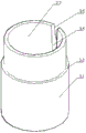
Fig. 3 is a schematic view of the pressure-bearing mechanism of the present invention.
Fig. 4 is a schematic view of the pressing mechanism of the present invention.
Wherein, 1, the carousel, 2, bottom positioning mechanism, 2.1, the fixed plate, 2.2, the position sleeve, 2.3, lifting unit, 2.4, sliding sleeve, 2.5, accommodate the lead screw, 3, the pressure-bearing mechanism, 3.1, circular sleeve, 3.2, adjusting unit, 3.3, the external screw thread sleeve, 3.4, the chute, 3.5, the discharge gate, 4, hold-down mechanism, 4.1, the fixed block, 4.2, the screw pole, 4.3, press the briquetting, 5, rotary mechanism.
Detailed Description
The present invention will now be further elucidated with reference to the accompanying drawings.
As shown in fig. 1-4, a clamping fixture for drilling a guide hole in a guide sleeve of a hydraulic cylinder comprises a rotary table 1, a bottom positioning mechanism 2, a pressure-bearing mechanism 3 and a pressing mechanism 4, wherein a rotary mechanism 5 is fixed on the back surface of the rotary table 1 in a cylinder welding manner, the bottom positioning mechanism 2 is fixed on the front surface of the rotary table 1 in a bolt fastening manner, the bottom positioning mechanism 2 comprises a fixed plate 2.1 and a positioning sleeve 2.2, the fixed plate 2.1 and the rotary table 1 are fixedly connected (a bolt penetrates through the fixed plate 2.1 and extends into the rotary table 1, and the tail of the bolt is in threaded fixation with the rotary table 1, so that the fixed plate 2.1 is locked on the rotary table 1 by the bolt), the positioning sleeve 2.2 is fixed on the fixed plate 2.1 in a welding manner, during positioning, the bottom of the guide sleeve is inserted into the positioning sleeve 2.2 to complete positioning, and the outer wall of the bottom of the guide sleeve is; a pressure-bearing mechanism 3 is fixed on the rotary table 1 in a bolt locking mode (the fixing mode of the pressure-bearing mechanism 3 is consistent with that of the fixing plate 2.1), wherein the pressure-bearing mechanism 3 is a circular sleeve 3.1, the circular sleeve 3.1 abuts against the guide sleeve, an inner hole of the circular sleeve 3.1 is larger than a guide hole of the guide sleeve, a discharge hole 3.5 is formed in the wall of the circular sleeve 3.1 and used for discharging scraps in the circular sleeve 3.1, a chute 3.4 is formed in the inner wall of the circular sleeve 3.1, and the chute 3.4 is communicated with the discharge hole 3.5; the pressing mechanism 4 is fixed on the rotary table 1 in a bolt locking mode, the pressing mechanism 4 comprises a fixing block 4.1, a screw rod 4.2 and a pressing block 4.3, wherein the fixing block 4.1 is fixed on the rotary table 1 through a bolt and the fixing block 4.1 is located right above the positioning sleeve 2.2, the screw rod 4.2 facing the positioning sleeve 2.2 is fixed below the fixing block 4.1 in a welding mode, the pressing block 4.3 in threaded fit with the screw rod 4.2 is sleeved on the screw rod 4.2, the pressing block 4.3 is rotated, the pressing block 4.3 is pressed on a workpiece, and the workpiece can be loosened by reversely rotating the pressing block 4.3.
The bottom positioning mechanism 2 and the pressure bearing mechanism 3 are detachably connected with the rotary table 1 (namely a plurality of bolt holes are formed in the rotary table 1, and the bottom positioning mechanism 2 and the pressure bearing mechanism 3 are locked on the rotary table 1 through bolts), so that the bottom positioning mechanism 2 and the pressure bearing mechanism 3 can be replaced according to the size of a workpiece, and the adaptive assembly of the workpiece is realized.
A fixed plate 2.1 is fixed at the bottom of a positioning sleeve 2.2, a lifting assembly 2.3 is arranged between the fixed plate 2.1 and the positioning sleeve 2.2, the lifting assembly comprises a sliding sleeve 2.4 and an adjusting screw rod 2.5, a bolt hole is formed in the fixed plate 2.1 and is positioned at the bottom of the positioning sleeve 2.2, the adjusting screw rod 2.5 (the adjusting screw rod 2.5 is in threaded fit with the bolt hole in the fixed plate 2.1) is inserted into the bolt hole, one end of the adjusting screw rod 2.5 is abutted against the bottom of the positioning sleeve 2.2, the sliding sleeves 2.4 are arranged on the positioning sleeve 2.2 and the fixed plate 2.1, one sliding sleeve 2.4 is fixed at the top of the fixed plate 2.1 in a welding manner, the other sliding sleeve 2.4 is fixed at the bottom of the positioning sleeve 2.2 in a welding manner, the adjusting screw rod 2.5 is positioned in the inner cylinders of the two sliding sleeves 2.4, thus the position of the positioning mechanism 2.5 (the adjusting screw rod 2.5 is rotated, promote the rising of position sleeve 2.2 through accommodate the lead screw 2.5, when accommodate the lead screw descends, position sleeve 2.2 descends under the effect of self gravity, and two slip sleeves 2.4's that set up main function uses and leads, prevents that 2.2 a section of thick bamboo of position sleeve skew vertical direction and unable location), be suitable for through foretell regulation with different work pieces, great reduction in production cost like this.
An adjusting component 3.2 is arranged between the pressure-bearing mechanism 3 and the rotary table 1, the adjusting component 3.2 is an external thread sleeve 3.3, an internal thread matched with the external thread sleeve 3.3 is arranged on the inner wall of the circular sleeve 3.1, a discharge hole 3.5 is arranged on the external thread sleeve 3.3, so that the discharge of scraps is completed, the position of the pressure-bearing mechanism 3 is adjusted through the thickness of a workpiece, and the workpiece is supported by the pressure-bearing mechanism 3.
Claims (4)
1. A clamping fixture for drilling a guide hole in a guide sleeve of a hydraulic cylinder comprises a rotary table, a bottom positioning mechanism, a pressure-bearing mechanism and a pressing mechanism, wherein a rotating mechanism is fixed on the back surface of the rotary table; the rotary table is provided with a pressure-bearing mechanism, wherein the pressure-bearing mechanism is a circular sleeve which is abutted against the guide sleeve, an inner hole of the circular sleeve is larger than a guide hole of the guide sleeve, the wall of the circular sleeve is provided with a discharge hole, the inner wall of the circular sleeve is provided with a chute, and the chute is communicated with the discharge hole; be fixed with hold-down mechanism on the carousel, hold-down mechanism includes fixed block, lead screw and presses the briquetting, and wherein the fixed block is fixed on the carousel and the fixed block is located the position sleeve directly over, is fixed with the lead screw towards the position sleeve in the below of fixed block, and the cover has the briquetting of pressing with lead screw thread fit on the lead screw, presses the briquetting to press on the work piece.
2. The clamping fixture for drilling the guide hole in the guide sleeve of the hydraulic cylinder as recited in claim 1, wherein the bottom positioning mechanism and the pressure-bearing mechanism are detachably connected with the rotary table.
3. The clamping fixture for drilling the guide hole of the hydraulic cylinder guide sleeve as recited in claim 2, wherein a fixing plate is fixed at the bottom of the positioning sleeve, a lifting assembly is disposed between the fixing plate and the positioning sleeve, the lifting assembly comprises a sliding sleeve and an adjusting screw rod, a bolt hole is formed in the fixing plate and located at the bottom of the positioning sleeve, the adjusting screw rod is inserted into the bolt hole, one end of the adjusting screw rod abuts against the bottom of the positioning sleeve, sliding sleeves are disposed on the positioning sleeve and the fixing plate, one of the sliding sleeves is sleeved on the other sliding sleeve, and the adjusting screw rod is located in inner cylinders of the two sliding sleeves.
4. The clamping fixture for drilling the guide hole of the guide sleeve of the hydraulic cylinder according to claim 3, wherein an adjusting component is arranged between the pressure-bearing mechanism and the rotary table, the adjusting component is an externally threaded sleeve, and an internal thread matched with the externally threaded sleeve is formed on the inner wall of the circular sleeve.
Priority Applications (1)
| Application Number | Priority Date | Filing Date | Title |
|---|---|---|---|
| CN201922416701.4U CN211332203U (en) | 2019-12-29 | 2019-12-29 | Clamping fixture for drilling guide hole in hydraulic cylinder guide sleeve |
Applications Claiming Priority (1)
| Application Number | Priority Date | Filing Date | Title |
|---|---|---|---|
| CN201922416701.4U CN211332203U (en) | 2019-12-29 | 2019-12-29 | Clamping fixture for drilling guide hole in hydraulic cylinder guide sleeve |
Publications (1)
| Publication Number | Publication Date |
|---|---|
| CN211332203U true CN211332203U (en) | 2020-08-25 |
Family
ID=72097753
Family Applications (1)
| Application Number | Title | Priority Date | Filing Date |
|---|---|---|---|
| CN201922416701.4U Active CN211332203U (en) | 2019-12-29 | 2019-12-29 | Clamping fixture for drilling guide hole in hydraulic cylinder guide sleeve |
Country Status (1)
| Country | Link |
|---|---|
| CN (1) | CN211332203U (en) |
Cited By (2)
| Publication number | Priority date | Publication date | Assignee | Title |
|---|---|---|---|---|
| CN112276626A (en) * | 2020-11-12 | 2021-01-29 | 常德市格佳机械有限公司 | Positioning tool for machining multiple stations of guide sleeve |
| CN114414118A (en) * | 2022-01-28 | 2022-04-29 | 航天精工股份有限公司 | Frock is measured to self-plugging rivet core bar holding power |
-
2019
- 2019-12-29 CN CN201922416701.4U patent/CN211332203U/en active Active
Cited By (4)
| Publication number | Priority date | Publication date | Assignee | Title |
|---|---|---|---|---|
| CN112276626A (en) * | 2020-11-12 | 2021-01-29 | 常德市格佳机械有限公司 | Positioning tool for machining multiple stations of guide sleeve |
| CN112276626B (en) * | 2020-11-12 | 2022-03-08 | 常德市格佳机械有限公司 | Positioning tool for machining multiple stations of guide sleeve |
| CN114414118A (en) * | 2022-01-28 | 2022-04-29 | 航天精工股份有限公司 | Frock is measured to self-plugging rivet core bar holding power |
| CN114414118B (en) * | 2022-01-28 | 2024-04-16 | 航天精工股份有限公司 | Core bar holding force measuring tool for self-plugging rivet |
Similar Documents
| Publication | Publication Date | Title |
|---|---|---|
| CN211332203U (en) | Clamping fixture for drilling guide hole in hydraulic cylinder guide sleeve | |
| CN108907736B (en) | Connecting rod processing system | |
| CN204396901U (en) | A kind of four station numerically controlled lathe Quick replaceable drill bit fixtures | |
| CN201799635U (en) | Jig of machine tool for internally centring and compacting at end surfaces | |
| CN101081438A (en) | Automatic material providing method of digital control lathes and the automatic material providing device | |
| CN108971578B (en) | Drilling mould for porous workpiece | |
| CN104339041B (en) | For processing the automatic cut-to-length floating support device of adapter | |
| CN110142623A (en) | The work-piece fixation clamp of the axial rotary drilling of deep hole | |
| CN203330448U (en) | Machining device capable of machining inner hole of cylinder sleeve | |
| KR20140058271A (en) | Head stock having function drawing off the workpiece | |
| CN101513718B (en) | Automatic positioning compacting device | |
| CN213889060U (en) | Eccentric bearing turning clamp device | |
| CN110961688B (en) | Clamp center hole drilling machine | |
| CN210996676U (en) | Drilling machine fixture for stepped thin-wall revolving body | |
| CN211661253U (en) | Spiral lifting automatic centering hydraulic pressing chuck for gear machining | |
| CN211539626U (en) | Accurate counter sinking device of braking products | |
| CN204277133U (en) | For processing the automatic cut-to-length floating support device of crossover sub | |
| CN106166684B (en) | A kind of special fixture of clutch compressing disc hinge seat pin hole | |
| CN211465610U (en) | Flange plate part step hole boring clamp | |
| CN219026754U (en) | Automatic drilling machine | |
| CN205218126U (en) | Lead screw hitching leg drilling mould | |
| CN217097253U (en) | Piston pin hole processing device | |
| CN209077866U (en) | For processing the device of large diameter and inner thread hole inclined oil hole of air | |
| CN215280006U (en) | Multi-position drilling tool for bearing block inserts | |
| CN211841056U (en) | Machine tool fixture device for machining |
Legal Events
| Date | Code | Title | Description |
|---|---|---|---|
| GR01 | Patent grant | ||
| GR01 | Patent grant |