CN211310279U - Winding machine for conveyer belt production - Google Patents
Winding machine for conveyer belt production Download PDFInfo
- Publication number
- CN211310279U CN211310279U CN201922374508.9U CN201922374508U CN211310279U CN 211310279 U CN211310279 U CN 211310279U CN 201922374508 U CN201922374508 U CN 201922374508U CN 211310279 U CN211310279 U CN 211310279U
- Authority
- CN
- China
- Prior art keywords
- fixedly connected
- support
- motor
- connecting plate
- wind
- Prior art date
- Legal status (The legal status is an assumption and is not a legal conclusion. Google has not performed a legal analysis and makes no representation as to the accuracy of the status listed.)
- Active
Links
- 238000004804 winding Methods 0.000 title claims abstract description 39
- 238000004519 manufacturing process Methods 0.000 title claims abstract description 15
- 230000006835 compression Effects 0.000 claims abstract description 13
- 238000007906 compression Methods 0.000 claims abstract description 13
- 238000003825 pressing Methods 0.000 claims description 2
- 238000005096 rolling process Methods 0.000 abstract description 9
- 230000009286 beneficial effect Effects 0.000 abstract description 2
- 239000002131 composite material Substances 0.000 description 2
- 239000000463 material Substances 0.000 description 2
- 238000000034 method Methods 0.000 description 2
- 229910000831 Steel Inorganic materials 0.000 description 1
- 230000004075 alteration Effects 0.000 description 1
- 239000004568 cement Substances 0.000 description 1
- 238000004939 coking Methods 0.000 description 1
- 239000004744 fabric Substances 0.000 description 1
- 239000000835 fiber Substances 0.000 description 1
- 230000003993 interaction Effects 0.000 description 1
- 239000002184 metal Substances 0.000 description 1
- 238000005272 metallurgy Methods 0.000 description 1
- 238000012986 modification Methods 0.000 description 1
- 230000004048 modification Effects 0.000 description 1
- 239000005060 rubber Substances 0.000 description 1
- 239000010959 steel Substances 0.000 description 1
- 239000000126 substance Substances 0.000 description 1
- 238000006467 substitution reaction Methods 0.000 description 1
Images


Landscapes
- Winding Of Webs (AREA)
Abstract
The utility model discloses a kinking machine is used in conveyer belt production, including the base, the equal fixedly connected with connecting plate of extension end of two lift hydraulic pressure posts, the fixed motor that is equipped with in one side on connecting plate top, the output fixedly connected with lead screw of motor, the one end fixedly connected with wind-up roll of lead screw, middle part between fixing base and the backup pad is rotated through the pivot and is connected with the compression roller, the beneficial effects of the utility model are that: through the output fixedly connected with lead screw of motor, and the one end fixedly connected with wind-up roll of lead screw, drive the wind-up roll through machinery and rotate and twine the conveyer belt, improve winding efficiency, through the setting of compression roller, compress tightly the conveyer belt when the wind-up roll rolling of being convenient for, improve winding quality, the both sides on backup pad top are all through lift hydraulic pressure post fixedly connected with connecting plate to adjust the height between wind-up roll and the compression roller, be convenient for adjust rolling thickness.
Description
Technical Field
The utility model relates to a kinking machine, in particular to kinking machine is used in conveyer belt production.
Background
The conveyer belt is a composite product of rubber, fiber and metal or a composite product of plastic and fabric, which is used in the belt conveyer belt to carry and convey materials. The conveyer belt is widely applied to occasions with short conveying distance and small conveying amount in the industries of cement, coking, metallurgy, chemical industry, steel and the like. The conveyer belt is used portably, at the winding rolling in-process of conveyer belt, need use the winding machine to come the rolling conveyer belt of being convenient for, the material resources of using manpower sparingly.
However, the existing winding machine for conveying belt production is simple in structure, the conveying belt is usually wound manually, the winding efficiency is low, a pressing structure is not provided when the existing winding machine for conveying belt production is wound, the winding thickness is limited, and therefore the existing winding machine for conveying belt production still has a great deal of problems.
SUMMERY OF THE UTILITY MODEL
An object of the utility model is to provide a coiler for conveyer belt production to solve the current coiler for conveyer belt production that proposes in the above-mentioned background art simple structure, it is usually manual to twine the conveyer belt, and does not possess the compact structure during the coiling of the coiler for the current conveyer belt production, and the limited problem of rolling thickness.
In order to achieve the above object, the utility model provides a following technical scheme: the utility model provides a kinking machine is used in conveyer belt production, includes the base, one side on base upper portion is provided with the backup pad, and the opposite side is provided with the fixing base, the equal fixedly connected with lift hydraulic pressure post in both sides on backup pad top, two the equal fixedly connected with connecting plate in extension end of lift hydraulic pressure post, the fixed motor that is equipped with in one side on connecting plate top, the output fixedly connected with lead screw of motor, the one end fixedly connected with wind-up roll of lead screw, middle part between fixing base and the backup pad is rotated through the pivot and is connected with the compression roller.
As an optimal technical scheme of the utility model, the fixed flush mounting plate that is equipped with in top of base, fixed lift hydraulic pressure post switch and the motor switch of being equipped with on the flush mounting plate of switch, lift hydraulic pressure post and motor are respectively through lift hydraulic pressure post switch and motor switch and external power supply electric connection.
As a preferred technical scheme of the utility model, the opposite side fixedly connected with fixing base on base top, one side fixedly connected with support on fixing base top, the top swing joint of support has the second support, the opening has all been seted up, two to one side of second support and one side of support the open-ended inside all alternates and is connected with fastening bolt.
As a preferred technical scheme of the utility model, the first support of one end fixedly connected with of connecting plate, the top of first support and second support is all seted up flutedly, the both ends of wind-up roll are located the inside of the recess that corresponds respectively.
As a preferred technical scheme of the utility model, the opposite side fixedly connected with connecting seat on connecting plate top, the middle part of connecting seat one end is rotated and is connected with the toothed disc, the fixed scale ring that is equipped with of positive avris of toothed disc.
As a preferred technical scheme of the utility model, the outside swing joint of lead screw has the movable block, the outer wall of movable block is fixed and is equipped with chain gear, chain gear is connected with the outer wall meshing of toothed disc.
As the utility model discloses a preferred technical scheme, the compression roller is just right with the wind-up roll position, a plurality of extension boards of outside fixedly connected with of wind-up roll.
Compared with the prior art, the beneficial effects of the utility model are that: the utility model relates to a kinking machine is used in conveyer belt production, output fixedly connected with lead screw through the motor, and the one end fixedly connected with wind-up roll of lead screw, drive the wind-up roll through machinery and rotate and twine the conveyer belt, improve winding efficiency, through the setting of compression roller, compress tightly the conveyer belt when the wind-up roll rolling of being convenient for, improve winding quality, the both sides on backup pad top are all through lift hydraulic pressure post fixedly connected with connecting plate to adjust the height between wind-up roll and the compression roller, be convenient for adjust rolling thickness.
Drawings
FIG. 1 is a schematic structural view of the present invention;
fig. 2 is a schematic structural view of a front side of a first bracket of the present invention;
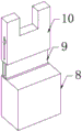
fig. 3 is a schematic view of a second bracket structure of the present invention.
In the figure: 1. a base; 2. lifting the hydraulic column; 3. a connecting plate; 4. a motor; 5. a screw rod; 6. a wind-up roll; 7. a first bracket; 8. a fixed seat; 9. a support; 10. a second bracket; 11. a connecting seat; 12. a gear plate; 13. a scale ring; 14. a movable block; 15. a compression roller; 16. and (4) a support plate.
Detailed Description
The technical solutions in the embodiments of the present invention will be described clearly and completely with reference to the accompanying drawings in the embodiments of the present invention, and it is obvious that the described embodiments are only some embodiments of the present invention, not all embodiments. Based on the embodiments in the present invention, all other embodiments obtained by a person skilled in the art without creative work belong to the protection scope of the present invention.
Please refer to fig. 1-3, the utility model provides a kinking machine is used in conveyer belt production, including base 1, one side on 1 upper portion of base is provided with the backup pad, and the opposite side is provided with fixing base 8, the equal fixedly connected with lift hydraulic cylinder 2 in both sides on backup pad top, the equal fixedly connected with connecting plate 3 of extension end of two lift hydraulic cylinder 2 to adjust the height between wind-up roll 6 and the compression roller 15, be convenient for adjust rolling thickness, the fixed motor 4 that is equipped with in one side on 3 tops of connecting plate, the output end fixedly connected with lead screw 5 of motor 4, the one end fixedly connected with wind-up roll 6 of lead screw 5, middle part between fixing base 8 and the backup pad is rotated through the pivot and is connected with compression roller 15, compress tightly the conveyer belt when being convenient for the.
Preferably, a switch panel is fixedly arranged at the top end of the base 1, a lifting hydraulic column switch and a motor switch are fixedly arranged on the switch panel, and the lifting hydraulic column 2 and the motor 4 are respectively electrically connected with an external power supply through the lifting hydraulic column switch and the motor switch, so that the operation of workers is facilitated; the other side of the top end of the base 1 is fixedly connected with a fixed seat 8, one side of the top end of the fixed seat 8 is fixedly connected with a support 9, the top end of the support 9 is movably connected with a second support 10, openings are formed in one side of the second support 10 and one side of the support 9, fastening bolts are inserted and connected into the two openings, and the height of the second support 10 is conveniently fixed so as to support the wind-up roll 6; one end of the connecting plate 3 is fixedly connected with a first support 7, the top ends of the first support 7 and the second support 10 are respectively provided with a groove, and two ends of the winding roller 6 are respectively positioned in the corresponding grooves, so that the winding roller 6 is conveniently supported; the other side of the top end of the connecting plate 3 is fixedly connected with a connecting seat 11, the middle part of one end of the connecting seat 11 is rotatably connected with a gear disc 12, and the side of the front surface of the gear disc 12 is fixedly provided with a scale ring 13 so as to be convenient for observing the number of winding turns; the outer part of the screw rod 5 is movably connected with a movable block 14, the outer wall of the movable block 14 is fixedly provided with a chain gear, the chain gear is meshed with the outer wall of the gear disc 12, when the motor 4 works, the screw rod 5 rotates to drive the movable block 14 to move so as to be meshed with the outer wall of the gear disc 12, the gear disc 12 can conveniently rotate, and the number of winding turns can be determined; the compression roller 15 is opposite to the winding roller 6, and the plurality of support plates 16 are fixedly connected to the outer portion of the winding roller 6, so that friction force is increased, and the conveying belt can be wound conveniently.
When the winding machine is used, firstly, one end of a conveying belt is fixed on a winding roller 6, one side of the conveying belt is contacted with a compression roller 15, a power supply is switched on, a motor switch is turned on, a motor 4 works to drive a lead screw 5 to rotate, the lead screw 5 rotates to drive a movable block 14 to move, meanwhile, the movable block 14 is meshed with a gear disc 12 to be connected, so that the number of turns of the winding roller 6 winding the conveying belt is obtained, the motor 4 works to drive the winding roller 6 to rotate to wind the conveying belt, the winding efficiency is improved through a plurality of support plates 16, when the winding thickness of the conveying belt needs to be adjusted, a lifting hydraulic column switch is turned on, so that the winding roller 6 is driven to move up and down through a lifting hydraulic column 2, the winding thickness of the conveying belt is convenient to adjust, in the winding process of the conveying belt, through the arrangement of a first support 7 and a second, being convenient for support wind-up roll 6, stability when improving the winding rolling.
In the description of the present invention, it should be understood that the indicated orientation or positional relationship is based on the orientation or positional relationship shown in the drawings, and is only for convenience of description and simplification of description, and does not indicate or imply that the indicated device or element must have a particular orientation, be constructed and operated in a particular orientation, and thus should not be construed as limiting the present invention.
In the present invention, unless otherwise explicitly specified or limited, for example, it may be fixedly connected, detachably connected, or integrated; can be mechanically or electrically connected; they may be directly connected or indirectly connected through an intermediate medium, and may be connected through the inside of two elements or in an interaction relationship between two elements, unless otherwise specifically defined, and the specific meaning of the above terms in the present invention will be understood by those skilled in the art according to specific situations.
Although embodiments of the present invention have been shown and described, it will be appreciated by those skilled in the art that changes, modifications, substitutions and alterations can be made in these embodiments without departing from the principles and spirit of the invention, the scope of which is defined in the appended claims and their equivalents.
Claims (7)
1. The utility model provides a kinking machine is used in conveyer belt production, includes base (1), its characterized in that, one side on base (1) upper portion is provided with the backup pad, and the opposite side is provided with fixing base (8), the equal fixedly connected with lift hydraulic cylinder (2) in both sides on backup pad top, two the equal fixedly connected with connecting plate (3) of extension end of lift hydraulic cylinder (2), one side on connecting plate (3) top is fixed and is equipped with motor (4), the output fixedly connected with lead screw (5) of motor (4), the one end fixedly connected with wind-up roll (6) of lead screw (5), middle part between fixing base (8) and the backup pad is rotated through the pivot and is connected with compression roller (15).
2. The winding machine for producing the conveying belt according to claim 1, wherein a switch panel is fixedly arranged at the top end of the base (1), a lifting hydraulic column switch and a motor switch are fixedly arranged on the switch panel, and the lifting hydraulic column (2) and the motor (4) are electrically connected with an external power supply through the lifting hydraulic column switch and the motor switch respectively.
3. The winding machine for producing the conveying belt according to claim 1, wherein a support (9) is fixedly connected to one side of the top end of the fixing seat (8), a second support (10) is movably connected to the top end of the support (9), openings are formed in one side of the second support (10) and one side of the support (9), and fastening bolts are inserted into the two openings.
4. The winding machine for producing the conveying belt according to claim 1, wherein one end of the connecting plate (3) is fixedly connected with a first support (7), the top ends of the first support (7) and the second support (10) are respectively provided with a groove, and two ends of the winding roller (6) are respectively positioned in the corresponding grooves.
5. The winding machine for the production of the conveying belt as claimed in claim 1, wherein the other side of the top end of the connecting plate (3) is fixedly connected with a connecting seat (11), the middle of one end of the connecting seat (11) is rotatably connected with a gear disc (12), and the side of the front surface of the gear disc (12) is fixedly provided with a scale ring (13).
6. The winding machine for producing the conveying belt as claimed in claim 1, characterized in that a movable block (14) is movably connected to the outside of the screw rod (5), a chain gear is fixedly arranged on the outer wall of the movable block (14), and the chain gear is engaged with the outer wall of the gear disc (12).
7. The winding machine for producing the conveying belt according to claim 1, wherein the pressing roller (15) is opposite to the winding roller (6), and a plurality of support plates (16) are fixedly connected to the outer part of the winding roller (6).
Priority Applications (1)
| Application Number | Priority Date | Filing Date | Title |
|---|---|---|---|
| CN201922374508.9U CN211310279U (en) | 2019-12-26 | 2019-12-26 | Winding machine for conveyer belt production |
Applications Claiming Priority (1)
| Application Number | Priority Date | Filing Date | Title |
|---|---|---|---|
| CN201922374508.9U CN211310279U (en) | 2019-12-26 | 2019-12-26 | Winding machine for conveyer belt production |
Publications (1)
| Publication Number | Publication Date |
|---|---|
| CN211310279U true CN211310279U (en) | 2020-08-21 |
Family
ID=72054721
Family Applications (1)
| Application Number | Title | Priority Date | Filing Date |
|---|---|---|---|
| CN201922374508.9U Active CN211310279U (en) | 2019-12-26 | 2019-12-26 | Winding machine for conveyer belt production |
Country Status (1)
| Country | Link |
|---|---|
| CN (1) | CN211310279U (en) |
-
2019
- 2019-12-26 CN CN201922374508.9U patent/CN211310279U/en active Active
Similar Documents
| Publication | Publication Date | Title |
|---|---|---|
| CN211310279U (en) | Winding machine for conveyer belt production | |
| CN220299459U (en) | Anti-slip feeder structure | |
| CN214441959U (en) | Steel band coiling mechanism | |
| CN201394620Y (en) | Hoop-bending machine with an elastic compacting feeding device | |
| CN218361436U (en) | Section bar straightening device for fishing boat manufacturing | |
| CN217993238U (en) | Roll forming device for waterproof coiled material | |
| CN215785749U (en) | Be applied to steel wire straightening mechanism of steel wire drawing production line | |
| CN214588450U (en) | Winding mechanism for electronic transformer production | |
| CN210280490U (en) | Correcting device for steel bar detection | |
| CN115683818A (en) | Portable rope storage and safety factor detection device | |
| CN212021421U (en) | Synchronous belt forming equipment | |
| CN212024222U (en) | Waterproofing membrane's coiling mechanism | |
| CN210312712U (en) | Automatic winding machine for producing water stop | |
| CN207871719U (en) | A kind of production line of petrochemical industry filter screen | |
| CN111300545B (en) | Continuous die-cutting machine | |
| CN215355465U (en) | Special integral straightening roller for heavy rail | |
| CN201978978U (en) | Opening type automatic elevating four-roller rolling machine | |
| CN212810822U (en) | Terminal production is with rolling up hole device | |
| CN210958090U (en) | Stator core's book folds device | |
| CN212827052U (en) | Anti-deviation auxiliary device of flatting machine | |
| CN219535841U (en) | Iron core cramp closing device | |
| CN221089434U (en) | Longitudinal and tangential line locking device for aerated bricks | |
| CN216566545U (en) | Roll-up device for producing paper plastic film packaging material | |
| CN110900411B (en) | Cutting device and cutting method for hot-dip galvanized steel strand production | |
| CN210547029U (en) | Electric transmission device of continuous rolling unit |
Legal Events
| Date | Code | Title | Description |
|---|---|---|---|
| GR01 | Patent grant | ||
| GR01 | Patent grant | ||
| PE01 | Entry into force of the registration of the contract for pledge of patent right |
Denomination of utility model: A winding machine for conveyor belt production Granted publication date: 20200821 Pledgee: Shandong Qufu Rural Commercial Bank Co.,Ltd. Pledgor: Shandong Juntai Rubber Plastic Co.,Ltd. Registration number: Y2024980001641 |
|
| PE01 | Entry into force of the registration of the contract for pledge of patent right |