CN211304420U - Novel punching transmission mechanism - Google Patents
Novel punching transmission mechanism Download PDFInfo
- Publication number
- CN211304420U CN211304420U CN201922104418.8U CN201922104418U CN211304420U CN 211304420 U CN211304420 U CN 211304420U CN 201922104418 U CN201922104418 U CN 201922104418U CN 211304420 U CN211304420 U CN 211304420U
- Authority
- CN
- China
- Prior art keywords
- lower die
- block
- driving block
- cavity
- side wall
- Prior art date
- Legal status (The legal status is an assumption and is not a legal conclusion. Google has not performed a legal analysis and makes no representation as to the accuracy of the status listed.)
- Active
Links
Images
Landscapes
- Perforating, Stamping-Out Or Severing By Means Other Than Cutting (AREA)
Abstract
A novel punching transmission mechanism comprises an upper die driving block, an upper die pressing plate, a lower die block, a lower die driving block, a V-shaped guide rail, a lower die punch, a nitrogen spring and a limiting block, wherein the lower die driving block is provided with a through cavity, the lower die block is arranged in the through cavity, a lower driving inclined plane matched with the upper driving inclined plane of the upper die driving block is arranged on the left side wall of the through cavity, an installation part is arranged on the lower die driving block close to the right side wall of the through cavity, a plurality of lower die punches are arranged on the inner side wall of the installation part, and the upper die pressing plate is matched above the lower die block; the lower die driving block is slidably mounted on the V-shaped guide rail which is obliquely arranged, and nitrogen springs are arranged between the left end of the lower die driving block and the two limiting blocks. The utility model discloses go up mould drive block drive lower mould drive block, lower mould drive block drives the lower mould drift and carries out the side to punching a hole to the product in the lower module, and not only simple structure, reasonable in design, work efficiency is high moreover.
Description
Technical Field
The utility model belongs to the technical field of the stamping die technique and specifically relates to a novel drive mechanism punches a hole.
Background
In prior art, carry out the side blow hole operation to some sheet metal components usually, present side cut-out press most when punching a hole is gone up the fixed motionless lower mould of mould part and is gone on the side and punch a hole of going on that floats, and this side cut-out press structure is comparatively complicated, and work efficiency is not high, can not satisfy modern industry and the production requirement that the operation is higher and higher to the side of punching a hole.
Accordingly, there is a need for improvements and enhancements in the art.
SUMMERY OF THE UTILITY MODEL
To the weak point that exists among the prior art, the utility model aims at providing a simple structure, reasonable in design, novel drive mechanism that punches a hole that work efficiency is high.
In order to achieve the above object, the utility model adopts the following technical scheme:
a novel punching transmission mechanism comprises an upper die driving block, an upper die pressing plate, a lower die block, a lower die driving block, a V-shaped guide rail, a lower die punch, a nitrogen spring and a limiting block, wherein the lower die driving block is provided with a through cavity, the lower die block is arranged in the through cavity, a lower driving inclined plane matched with the upper driving inclined plane of the upper die driving block is arranged on the left side wall of the through cavity, an installation part is arranged on the lower die driving block close to the right side wall of the through cavity, a plurality of lower die punches are arranged on the inner side wall of the installation part, and the upper die pressing plate is matched above the lower die block; the lower die driving block is slidably mounted on the V-shaped guide rail which is obliquely arranged, and nitrogen springs are arranged between the left end of the lower die driving block and the two limiting blocks.
Compared with the prior art, the beneficial effects of the utility model are that:
due to the adoption of the structural design, the upper die driving block drives the lower die driving block, and the lower die driving block drives the lower die punch to laterally punch a hole on a product on the lower die block, so that the structure is simple, the design is reasonable, and the working efficiency is high.
Drawings
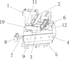
Fig. 1 is a schematic structural diagram of the present invention.
The reference numbers in the figures are respectively: (1) the device comprises an upper die driving block, (2) an upper die pressing plate, (3) a lower die block, (4) a lower die driving block, (5) a V-shaped guide rail, (6) a lower die punch, (7) a nitrogen spring, (8) a limiting block, (9) a penetrating cavity, (10) an upper driving inclined plane, (11) a lower driving inclined plane, and (12) an installation part.
Detailed Description
The invention will be described in further detail with reference to the accompanying drawings:
please refer to fig. 1, the utility model relates to a novel punching transmission mechanism, including upper die drive block 1, upper die platen 2, lower die block 3, lower die drive block 4, V-shaped guide rail 5, lower die punch 6, nitrogen spring 7 and stopper 8, lower die drive block 4 is equipped with and runs through chamber 9, run through the chamber 9 and embed said lower die block 3, the transverse width of running through the chamber is greater than the transverse width of lower die block, lower die block fixed mounting is on the die bed, have on the wall of said running through chamber left side with the upper drive inclined plane 10 matched with lower drive inclined plane 11 of said upper die drive block 1, be close to said running through chamber right side wall said lower die drive block on be equipped with installation department 12, the inside wall of said installation department 12 is provided with three said lower die punch 6, the top of said lower die block 3 still cooperates with upper die platen 2; lower mould drive block 4 through its below have with the V type slide groove of V type guide rail looks adaptation slider slidable mounting in the slope setting on V type guide rail 5, V type guide rail fixed mounting is on the die holder, the high slope setting in the left bottom right side of V type guide rail, all be equipped with nitrogen spring 7 between the left end of lower mould drive block 4 and two stopper 8.
The utility model discloses during operation, last mould drive block and last clamp plate are down, and last clamp plate pushes down the product of treating processing of arranging on the lower module, and last mould drive block down drives lower mould drive block and moves to left below along V type guide rail, and three lower mould drift on the lower mould drive block are treated the product of treating processing and are carried out the side blow hole operation, and nitrogen spring is compressed simultaneously; after the operation of taking the side blow hole is accomplished, go up mould drive block and last mould clamp plate and go upward, reset under the nitrogen gas spring's of lower mould drive block effect, the product on the lower module is taken away and is got rid of and get into next step's process.
To sum up, the utility model discloses an foretell structural design solves the weak point among the prior art, has characteristics such as simple structure, reasonable in design, work efficiency height.
The above description is only a preferred embodiment of the present invention, and is not intended to limit the present invention in any way, and any person skilled in the art may use the above-mentioned technical contents to change or modify the equivalent embodiments with equivalent changes, but all those persons do not depart from the technical contents of the present invention, and any simple modification, equivalent changes and modifications made to the above embodiments according to the technical essence of the present invention still belong to the scope of the technical solution of the present invention.
Claims (1)
1. The utility model provides a novel drive mechanism punches a hole which characterized in that: the device comprises an upper die driving block, an upper die pressing plate, a lower die driving block, a V-shaped guide rail, a lower die punch, a nitrogen spring and a limiting block, wherein the lower die driving block is provided with a through cavity, the lower die is arranged in the through cavity, a lower driving inclined plane matched with the upper driving inclined plane of the upper die driving block is arranged on the left side wall of the through cavity, an installation part is arranged on the lower die driving block close to the right side wall of the through cavity, a plurality of lower die punches are arranged on the inner side wall of the installation part, and the upper die pressing plate is matched above the lower die; the lower die driving block is slidably mounted on the V-shaped guide rail which is obliquely arranged, and nitrogen springs are arranged between the left end of the lower die driving block and the two limiting blocks.
Priority Applications (1)
| Application Number | Priority Date | Filing Date | Title |
|---|---|---|---|
| CN201922104418.8U CN211304420U (en) | 2019-11-29 | 2019-11-29 | Novel punching transmission mechanism |
Applications Claiming Priority (1)
| Application Number | Priority Date | Filing Date | Title |
|---|---|---|---|
| CN201922104418.8U CN211304420U (en) | 2019-11-29 | 2019-11-29 | Novel punching transmission mechanism |
Publications (1)
| Publication Number | Publication Date |
|---|---|
| CN211304420U true CN211304420U (en) | 2020-08-21 |
Family
ID=72060107
Family Applications (1)
| Application Number | Title | Priority Date | Filing Date |
|---|---|---|---|
| CN201922104418.8U Active CN211304420U (en) | 2019-11-29 | 2019-11-29 | Novel punching transmission mechanism |
Country Status (1)
| Country | Link |
|---|---|
| CN (1) | CN211304420U (en) |
-
2019
- 2019-11-29 CN CN201922104418.8U patent/CN211304420U/en active Active
Similar Documents
| Publication | Publication Date | Title |
|---|---|---|
| CN203695726U (en) | Composite wedge structure for side punching | |
| CN201223902Y (en) | Bending stamping mould | |
| CN209953581U (en) | Stamping die device is used in commodity circulation car production | |
| CN206104679U (en) | U -shaped forming die | |
| CN208866208U (en) | A kind of mold improving terminal production efficiency and stock utilization | |
| CN211304420U (en) | Novel punching transmission mechanism | |
| CN203330235U (en) | Inner side face punching mechanism of stamping die | |
| CN211464537U (en) | Stamping forming die structure with reverse slide wedge mechanism | |
| CN216911769U (en) | Stamping die with two different tapered wedge structures | |
| CN113560447B (en) | Reverse slider forming and stripping method | |
| CN214442287U (en) | Side punching die | |
| CN208321753U (en) | A kind of elastic pin stop of blanking die | |
| CN213256643U (en) | Stamping die who buckles punches a hole step by step | |
| CN210936699U (en) | Multi-station combined step mold structure | |
| CN209141097U (en) | A kind of split type die cutting die | |
| CN208787337U (en) | A kind of high-speed stamping die | |
| CN213104046U (en) | Side punching die mechanism for small parts | |
| CN111069430A (en) | Composite die structure with driving block on lower pressing core | |
| CN219746043U (en) | Composite bending progressive die structure for buckle type products | |
| CN213104193U (en) | Hardware stamping die's liftout mechanism | |
| CN211191621U (en) | Oblique punching forming progressive die | |
| CN211135176U (en) | Quick-change punching structure of rolling die | |
| CN213495938U (en) | Punching die for small-sized plate | |
| CN217964349U (en) | Spring pressing type discharging mechanism of multi-station progressive die for sheet metal part of vehicle body | |
| CN203635762U (en) | Side punching structure used in progressive die |
Legal Events
| Date | Code | Title | Description |
|---|---|---|---|
| GR01 | Patent grant | ||
| GR01 | Patent grant |