CN201223902Y - Bending stamping mould - Google Patents
Bending stamping mould Download PDFInfo
- Publication number
- CN201223902Y CN201223902Y CNU2008200710960U CN200820071096U CN201223902Y CN 201223902 Y CN201223902 Y CN 201223902Y CN U2008200710960 U CNU2008200710960 U CN U2008200710960U CN 200820071096 U CN200820071096 U CN 200820071096U CN 201223902 Y CN201223902 Y CN 201223902Y
- Authority
- CN
- China
- Prior art keywords
- punch
- die
- fen
- fixed plate
- die block
- Prior art date
- Legal status (The legal status is an assumption and is not a legal conclusion. Google has not performed a legal analysis and makes no representation as to the accuracy of the status listed.)
- Expired - Fee Related
Links
Images


Landscapes
- Bending Of Plates, Rods, And Pipes (AREA)
Abstract
The utility model discloses a bending stamping die, comprises an upper template and a lower template; a punch bearing plate and a punch fixed plate are sequentially fixed on the upper template; a die bearing plate and a die fixed plate are sequentially fixed on the lower template; a punch is fixedly arranged on the punch fixed plate; a die is fixedly arranged on the die fixed plate and at the corresponding location of the punch; a guide nail is fixedly arranged on the punch fixed plate in front of the punch and the punch feeding; a guide die is fixedly arranged on the die fixed plate and correspondingly to the location of the guide nail; a flexible material block flexibly matched with the die fixed plate is arranged on the surface of the die fixed plate; the punch comprises a plurality of parallel sub-punches; the sub-punch which is closest to the guide nail is the first sub-punch; and a flexible device is arranged at the bottom part of the first sub-punch. The utility model solves the problem of material belt stretching and improves the surface quality of the product, so that the product size can be easily controlled in the production process to reduce product reject rate and improve labor productivity.
Description
Technical field
The utility model relates to a kind of crooked diel.
Background technology
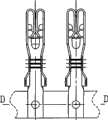
Product is the terminal product that a class has wavy crooked connecting band shown in the accompanying drawing 1,2,3, product material is each metalloid, the process of producing this series products is to adopt all kinds of " multi-station progressive stamping moulds " to carry out punching production, metal plate material band carries out a plurality of operations such as stamping-out, flanging, shaping, bending and finishes production on one pair of mould, its bending station (D-D place) is last procedure.Finish the production of this series products, the original production process method has two kinds, and the one, carrying out punching production on " multi-station progressive stamping mould " is semi-finished product, manufactures and designs the special-purpose bending die of a cover again, adopt operation manually to carry out bending and just can finish, the product size precision does not guarantee yet.The 2nd, adopt mould structure shown in the accompanying drawing 4, this mould structure is made up of part of the upper die and part of the lower die, the part of the upper die is by cope match-plate pattern 1, convex mould pad 2 and punch retainer 3 fixing compositions, the part of the lower die is by lower bolster 6, die backing plate 5 and die block 4 fixing compositions, the punch 9 of crooked usefulness and the correcting of correcting strip nail 10 are fixed on the punch retainer, its corresponding die 8 and correcting die 7 are fixed on the die block, wherein crooked punch 9 is that an integral body is inserted, its operation principle is: strip 22 moves from left to right, arrive bending mechanism and carry out bending, cope match-plate pattern 1 moves downward, correcting nail 10 is at first to strip 22 location, 9 pairs of strips of die 8 and punch 22 carry out bending then, the bending of material was flowed and can not be carried out fully from right to left this moment, often cause strip 22 by major injury, elongate, product size can't guarantee that the product percent defective is higher.
Summary of the invention
The purpose of this utility model is to overcome the defective that existing mold exists, and a kind of novel crooked diel is provided.
For achieving the above object, the utility model adopts following technical scheme: a kind of crooked diel, comprise cope match-plate pattern and lower bolster, solid punch backing plate and punch retainer successively on the cope match-plate pattern, anchor die-cushion plate and die block successively on the lower bolster, be mounted with punch on the punch retainer, be mounted with die with the punch correspondence position on the die block, at punch, be mounted with the correcting nail on the punch retainer in die charging the place ahead, be mounted with the correcting die on the die block of correcting nail correspondence position, be provided with lastics piece with the die block resilient engagement on described die block surface, described punch is made of a plurality of branch punch arranged side by side, the branch punch of the most close correcting nail is first fen punch, and the bottom of first fen punch is provided with elastic device.
Punch had three in described minute, was provided with second fen punch and the 3rd fen punch side by side in the back of first fen punch.
Described lower bolster, die backing plate and die block correspondence position have a plurality of through holes, and be installed with lastics piece push rod in the through hole and withstand on lastics piece bottom surface, top shock mount under the lastics piece push rod, the through hole oral area is provided with screw plug; Described cope match-plate pattern, convex mould pad and first fen punch correspondence position have through hole, position, first fen punch bottom has boss to be arranged in the chute of punch retainer, be installed with the bullet push rod in the through hole and withstand on first fen punch bottom surface, play top shock mount under the push rod, the through hole oral area is provided with screw plug.
The utility model is by improving mould structure, punch is divided into a plurality of branch punch arranged side by side, the lastics piece that first fen punch of the most close correcting nail cooperates with the die block surface elasticity cooperates, solve strip and elongated problem, improved product surface quality, make product size be easy to control in process of production, reduced the product percent defective, improve labor productivity.
Description of drawings
Figure 1 shows that the terminal product front view that has wavy crooked connecting band;
Fig. 2 is the left view of Fig. 1;
Fig. 3 is a D-D sectional view among Fig. 1;
Structural representation when Fig. 4 produces for adopting traditional moulds;
Fig. 5 is the utility model structural representation.
The specific embodiment
As shown in Figure 5, the utility model comprises cope match-plate pattern 1 and lower bolster 7, solid punch backing plate 2 and punch retainer 3 successively on the cope match-plate pattern 1, anchor die-cushion plate 6 and die block 5 successively on the lower bolster 7.First fen punch 15, second minute punch 14 and the 3rd fen punch 13 are installed on the punch retainer 3 side by side, cope match-plate pattern 1, convex mould pad 2 and first fen punch 15 correspondence position have through hole, position, first fen punch 15 bottom has boss 20 to be arranged in the chute 21 of punch retainer 3, be installed with bullet push rod 18 in the through hole and withstand on first fen punch 15 bottom surface, play 18 times top shock mounts 17 of push rod, the through hole oral area is provided with screw plug 16.Be mounted with die 12 with the punch correspondence position on the die block 5, on the punch retainer 3 in punch, die 12 charging the place aheads, be mounted with correcting nail 19, correcting is followed closely on the die block 5 of 19 correspondence positions and is mounted with correcting die 8, be provided with lastics piece 4 with die block 5 resilient engagement on die block 5 surfaces, lower bolster 7, die backing plate 6 and die block 5 correspondence positions have a plurality of through holes, be installed with lastics piece push rod 11 in the through hole and withstand on lastics piece 4 bottom surfaces, 11 times top shock mounts 10 of lastics piece push rod, the through hole oral area is provided with screw plug 9.
As shown in Figure 5, the utility model operation principle is: strip 22 moves from left to right, arrive bending mechanism and carry out bending, cope match-plate pattern 1 moves downward, correcting nail 19 is at first to strip 22 location, at the 3rd fen punch 13 when punch 14 did not contact strip 22 with second minute, first fen punch 15 and 4 actings in conjunction of lastics piece, clamping strip 22 continues to move downward together, die 12 begins to participate in strip 22 is carried out bending simultaneously, after strip 22 fully flowed from right to left, the 3rd fen punch 13 and second fen punch 14 just began to participate in bending, finish the bending of product.
Claims (3)
1, a kind of crooked diel, comprise cope match-plate pattern and lower bolster, solid punch backing plate and punch retainer successively on the cope match-plate pattern, anchor die-cushion plate and die block successively on the lower bolster, be mounted with punch on the punch retainer, be mounted with die with the punch correspondence position on the die block, at punch, be mounted with the correcting nail on the punch retainer in die charging the place ahead, be mounted with the correcting die on the die block of correcting nail correspondence position, it is characterized in that: be provided with lastics piece on described die block surface with the die block resilient engagement, described punch is made of a plurality of branch punch arranged side by side, the branch punch of the most close correcting nail is first fen punch, and the bottom of first fen punch is provided with elastic device.
2, a kind of crooked diel as claimed in claim 1 is characterized in that: punch had three in described minute, was provided with second fen punch and the 3rd fen punch side by side in the back of first fen punch.
3, a kind of crooked diel as claimed in claim 1 or 2, it is characterized in that: described lower bolster, die backing plate and die block correspondence position have a plurality of through holes, be installed with lastics piece push rod in the through hole and withstand on lastics piece bottom surface, top shock mount under the lastics piece push rod, the through hole oral area is provided with screw plug; Described cope match-plate pattern, convex mould pad and first fen punch correspondence position have through hole, position, first fen punch bottom has boss to be arranged in the chute of punch retainer, be installed with the bullet push rod in the through hole and withstand on first fen punch bottom surface, play top shock mount under the push rod, the through hole oral area is provided with screw plug.
Priority Applications (1)
| Application Number | Priority Date | Filing Date | Title |
|---|---|---|---|
| CNU2008200710960U CN201223902Y (en) | 2008-06-19 | 2008-06-19 | Bending stamping mould |
Applications Claiming Priority (1)
| Application Number | Priority Date | Filing Date | Title |
|---|---|---|---|
| CNU2008200710960U CN201223902Y (en) | 2008-06-19 | 2008-06-19 | Bending stamping mould |
Publications (1)
| Publication Number | Publication Date |
|---|---|
| CN201223902Y true CN201223902Y (en) | 2009-04-22 |
Family
ID=40596779
Family Applications (1)
| Application Number | Title | Priority Date | Filing Date |
|---|---|---|---|
| CNU2008200710960U Expired - Fee Related CN201223902Y (en) | 2008-06-19 | 2008-06-19 | Bending stamping mould |
Country Status (1)
| Country | Link |
|---|---|
| CN (1) | CN201223902Y (en) |
Cited By (7)
| Publication number | Priority date | Publication date | Assignee | Title |
|---|---|---|---|---|
| CN102527816A (en) * | 2011-12-15 | 2012-07-04 | 苏州和林精密科技有限公司 | Stamping mechanism with high planeness |
| CN102694332A (en) * | 2012-05-30 | 2012-09-26 | 苏州旭创精密模具有限公司 | RJ45 network cable interface terminal die |
| CN106391919A (en) * | 2015-08-13 | 2017-02-15 | 苏州井利电子股份有限公司 | Terminal bending device |
| CN106695329A (en) * | 2016-12-06 | 2017-05-24 | 温州市力博电子有限公司 | Multi-station belt synchronous assembly progressive die |
| CN108941373A (en) * | 2018-07-23 | 2018-12-07 | 张家界长兴汽车电器有限公司 | A kind of copper conductor drawing die and its application |
| CN109433957A (en) * | 2018-09-27 | 2019-03-08 | 贵州大道轴承机械有限公司 | A kind of bearing mnanufacture clamping ring stamping device |
| CN111844641A (en) * | 2020-07-21 | 2020-10-30 | 常德比克曼生物科技有限公司 | Production mould of culture vessel |
-
2008
- 2008-06-19 CN CNU2008200710960U patent/CN201223902Y/en not_active Expired - Fee Related
Cited By (8)
| Publication number | Priority date | Publication date | Assignee | Title |
|---|---|---|---|---|
| CN102527816A (en) * | 2011-12-15 | 2012-07-04 | 苏州和林精密科技有限公司 | Stamping mechanism with high planeness |
| CN102694332A (en) * | 2012-05-30 | 2012-09-26 | 苏州旭创精密模具有限公司 | RJ45 network cable interface terminal die |
| CN106391919A (en) * | 2015-08-13 | 2017-02-15 | 苏州井利电子股份有限公司 | Terminal bending device |
| CN106695329A (en) * | 2016-12-06 | 2017-05-24 | 温州市力博电子有限公司 | Multi-station belt synchronous assembly progressive die |
| CN106695329B (en) * | 2016-12-06 | 2019-06-18 | 温州市力博电子有限公司 | A kind of multi-station belt is synchronous to assemble progressive die |
| CN108941373A (en) * | 2018-07-23 | 2018-12-07 | 张家界长兴汽车电器有限公司 | A kind of copper conductor drawing die and its application |
| CN109433957A (en) * | 2018-09-27 | 2019-03-08 | 贵州大道轴承机械有限公司 | A kind of bearing mnanufacture clamping ring stamping device |
| CN111844641A (en) * | 2020-07-21 | 2020-10-30 | 常德比克曼生物科技有限公司 | Production mould of culture vessel |
Similar Documents
| Publication | Publication Date | Title |
|---|---|---|
| CN201223902Y (en) | Bending stamping mould | |
| CN201841203U (en) | Progressive die | |
| CN103658388B (en) | A kind of progressive die and method for producing automotive seat slideway retainer | |
| CN208976601U (en) | A kind of stamping die for reversely cutting off structure with double-slider | |
| CN205200348U (en) | Connecting piece punching press blanking mould | |
| CN202006242U (en) | Flanging molding die | |
| CN204018535U (en) | A kind of concave bottom bowl progressive die | |
| CN203711653U (en) | Bending structure for continuous punching die | |
| CN204182800U (en) | A kind of compound punching structure for punch level progressive die | |
| CN204770190U (en) | A mould structure for product shaping adjustment | |
| CN103878240B (en) | The shaping shaping mould of automobile engine exhaust system manifold | |
| CN109622749B (en) | High-precision punching die for nut plate | |
| CN207857660U (en) | A kind of novel shrapnel terminal continuous stamping die | |
| CN203565679U (en) | Continuous stamping die used for processing automotive hardware | |
| CN103624151A (en) | Novel progressive die | |
| CN202438641U (en) | U-shaped nail molding mold | |
| CN206519497U (en) | A kind of hinge pipe crimping mould | |
| CN206492837U (en) | One kind shaping and rotary-cut side continuous mold structure | |
| CN205217790U (en) | Fin continuous stamping die | |
| CN205519254U (en) | Take press device's drawing die in advance | |
| CN206169024U (en) | A system of processing for processing sliding support kerve | |
| CN205629097U (en) | Reverse tensile lid upgrades mould | |
| CN211489277U (en) | Support falling piece progressive die | |
| CN204171185U (en) | A kind of anti-sidesway mould with pre-bending mechanism | |
| CN208390792U (en) | A kind of magnet frame progressive die |
Legal Events
| Date | Code | Title | Description |
|---|---|---|---|
| C14 | Grant of patent or utility model | ||
| GR01 | Patent grant | ||
| C17 | Cessation of patent right | ||
| CF01 | Termination of patent right due to non-payment of annual fee |
Granted publication date: 20090422 Termination date: 20130619 |