CN211267744U - Rotary corn thresher - Google Patents
Rotary corn thresher Download PDFInfo
- Publication number
- CN211267744U CN211267744U CN201921176011.XU CN201921176011U CN211267744U CN 211267744 U CN211267744 U CN 211267744U CN 201921176011 U CN201921176011 U CN 201921176011U CN 211267744 U CN211267744 U CN 211267744U
- Authority
- CN
- China
- Prior art keywords
- wall
- threshing box
- box
- threshing
- pipe
- Prior art date
- Legal status (The legal status is an assumption and is not a legal conclusion. Google has not performed a legal analysis and makes no representation as to the accuracy of the status listed.)
- Active
Links
Images


Abstract
The utility model discloses a rotation type corn thresher, comprising a base plate, the top outer wall of bottom plate is equipped with threshing box, and the top outer wall of threshing box's one side outer wall and bottom plate all is equipped with the support column, and the top outer wall of two support columns is equipped with same conveying pipeline, the inner wall of conveying pipeline is equipped with conveying mechanism, and the conveying pipeline is close to the top outer wall of lower extreme and is equipped with the inlet pipe, and the bottom outer wall that the conveying pipeline is close to the top is equipped with the unloading pipe, threshing box's top outer wall is equipped with the passage, and the passage is close to the unloading pipe, threshing box's one side outer wall is. The utility model discloses a be provided with the pay-off subassembly, when carrying out the transport of maize, carry it to passage department through the pay-off subassembly to accomplish the feeding, improve the device's work efficiency, reduce the labour and drop into, the kernel of corn that also avoids the passage departure simultaneously causes the staff injured, and then improves the device's security performance.
Description
Technical Field
The utility model relates to an agricultural production technical field especially relates to a rotation type corn thresher.
Background
The thresher is an important harvesting machine for threshing crops such as wheat, rice, corn, sorghum, soybean and other coarse cereals, and is widely used in vast rural areas in China. Threshing machines have been used for decades in China, and the machine used for separating corn seeds from the ears of crops is called a threshing machine.
Through search, the patent with Chinese patent application number CN201720906068.5 discloses a multifunctional corn thresher, which comprises a machine body, a first motor, a belt pulley and an air inlet pipe. The threshing machine in the above patent has the following disadvantages: the feeding needs to be carried out manually in the comparison file, however, in the feeding process, the threshing machine threshes the corn cobs, and the corn kernels produced by threshing have the possibility of jumping out of the feeding hole, so that potential safety hazards exist, and the safety performance of the device is low.
SUMMERY OF THE UTILITY MODEL
The utility model aims to solve the defects in the prior art and provides a rotary corn thresher.
In order to achieve the above purpose, the utility model adopts the following technical scheme:
the utility model provides a rotation type corn thresher, includes the bottom plate, the top outer wall of bottom plate is equipped with threshing box, and the top outer wall of one side outer wall of threshing box and bottom plate all is equipped with the support column, and the top outer wall of two support columns is equipped with same conveying pipeline, the inner wall of conveying pipeline is equipped with conveying mechanism, and the conveying pipeline is close to the top outer wall of lower extreme and is equipped with the inlet pipe, and the conveying pipeline is close to the bottom outer wall on top and is equipped with the unloading pipe, threshing box's top outer wall is equipped with the passage, and the passage is close to.
Furthermore, a supporting plate is arranged on the outer wall of one side of the threshing box, a motor is arranged on the outer wall of the top of the supporting plate, a rotating shaft is arranged on an output shaft of the motor, and the outer wall of one side of the threshing box is arranged at the other end of the rotating shaft.
Further, one side inner wall of threshing box is equipped with the connecting axle, and the outer wall that the connecting axle is close to the other end and the outer wall of pivot all are equipped with the band pulley, and the outer wall of two band pulleys is equipped with the belt, and the outer wall of connecting axle is equipped with threshing frame.
Furthermore, the inner wall of the threshing box is provided with a sieve plate, and the outer wall of one side of the threshing box, which is close to the sieve plate, is provided with a discharge hole.
Further, the inner wall of threshing box below the sieve plate is provided with a drainage plate, the outer wall of one side of the threshing box close to the drainage plate is provided with a feed opening, and the top outer wall of the bottom plate close to the feed opening is provided with a material collecting box.
Furthermore, a dust collection box is arranged on the outer wall of the top of the bottom plate, and an air suction pump is arranged on the outer wall of the top of the dust collection box.
Furthermore, an air pipe is arranged on the inner wall of one side, close to the air extracting pump, of the threshing box, air nozzles are arranged on the outer wall of one side of the air pipe at equal intervals, the air inlet end of the air extracting pump is arranged on the inner wall of the air pipe, and the air conveying end of the air extracting pump is arranged on the inner wall of the dust collecting box.
Furthermore, the inner wall of the top of the threshing box and the inner wall of one side of the threshing box are both provided with motor heat pipes, and the inner wall of one side of the threshing box is provided with a humidity sensor.
The utility model has the advantages that:
1. through being provided with the pay-off subassembly, when carrying out the transport of maize, carry it to passage department through the pay-off subassembly to accomplish the feeding, improve the device's work efficiency, reduce labour input, also avoid the kernel of corn of passage departure to cause the staff injured simultaneously, and then improve the device's security performance.
2. Through being provided with collection dirt subassembly, carry out the in-process that the maize was threshed, produce a large amount of dusts and corn husks in the threshing box, collect it through collection dirt subassembly, prevent that dust and corn husks from discharging into the atmosphere and causing environmental pollution to improve the device's feature of environmental protection.
3. Through being provided with electric heating pipe and humidity transducer, when threshing incasement portion is too moist, start electric heating pipe and carry out heat treatment to threshing incasement portion, prevent moist air pollution kernel of corn.
Drawings
FIG. 1 is a schematic view of a rotary corn thresher according to embodiment 1;
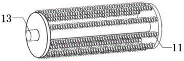
FIG. 2 is a schematic structural view of a threshing frame of the rotary corn thresher of the present invention;
fig. 3 is a schematic structural view of a rotary corn thresher according to embodiment 2.
In the figure: 1-bottom plate, 2-support column, 3-feeding mechanism, 4-feeding pipe, 5-feeding pipe, 6-air pump, 7-air pipe, 8-air nozzle, 9-discharging pipe, 10-material guiding pipe, 11-threshing frame, 12-threshing box, 13-connecting shaft, 14-belt, 15-motor, 16-support plate, 17-discharging port, 18-sieve plate, 19-material collecting box, 20-drainage plate, 21-dust collecting box, 22-humidity sensor and 23-electric heating pipe.
Detailed Description
The technical solution of the present patent will be described in further detail with reference to the following embodiments.
Reference will now be made in detail to embodiments of the present patent, examples of which are illustrated in the accompanying drawings, wherein like or similar reference numerals refer to the same or similar elements or elements having the same or similar function throughout. The embodiments described below with reference to the drawings are exemplary only for the purpose of explaining the present patent and are not to be construed as limiting the present patent.
In the description of this patent, it is to be understood that the terms "center," "upper," "lower," "front," "rear," "left," "right," "vertical," "horizontal," "top," "bottom," "inner," "outer," and the like are used in the orientations and positional relationships indicated in the drawings for the convenience of describing the patent and for the simplicity of description, and are not intended to indicate or imply that the referenced devices or elements must have a particular orientation, be constructed and operated in a particular orientation, and are not to be considered limiting of the patent.
In the description of this patent, it is noted that unless otherwise specifically stated or limited, the terms "mounted," "connected," and "disposed" are to be construed broadly and can include, for example, fixedly connected, disposed, detachably connected, disposed, or integrally connected and disposed. The specific meaning of the above terms in this patent may be understood by those of ordinary skill in the art as appropriate.
Example 1
Referring to fig. 1-2, a rotary corn thresher comprises a base plate 1, a threshing box 12 is fixed on the outer wall of the top of the base plate 1 through screws, supporting columns 2 are fixed on the outer wall of one side of the threshing box 12 and the outer wall of the top of the base plate 1 through screws, the same material conveying pipe 5 is fixed on the outer walls of the tops of the two supporting columns 2 through screws, a material conveying mechanism 3 is arranged on the inner wall of the material conveying pipe 5, a feeding pipe 4 is connected on the outer wall of the top of the material conveying pipe 5, which is close to the lower end, through a flange, a discharging pipe 9 is connected on the outer wall of the bottom of the material conveying pipe 5, which is close to the top end, a material guide pipe 10 is connected on the outer wall of the top of the threshing box 12 through a flange, the material guide pipe 10 is close to the discharging pipe 9, when the, the labor input is reduced, and meanwhile, the situation that the worker is injured due to the corn kernels flying out of the material guide pipe 10 is avoided, so that the safety performance of the device is improved.
Wherein, the outer wall of one side of threshing box 12 is fixed with a supporting plate 16 through a screw, the outer wall of the top of supporting plate 16 is fixed with a motor 15 through a screw, the output shaft of motor 15 is fixed with a rotating shaft through a shaft coupling, and the other end of the rotating shaft is fixed on the outer wall of one side of threshing box 12 through a bearing.
Wherein, the inner wall of one side of threshing box 12 is fixed with connecting axle 13 through the bearing, and the outer wall that connecting axle 13 is close to the other end and the outer wall of pivot all are fixed with the band pulley through the key, and the outer wall of two band pulleys has cup jointed belt 14, and the outer wall of connecting axle 13 passes through the fix with screw and threshes frame 11.
Wherein, the inner wall of the threshing box 12 is fixed with a sieve plate 18 through screws, and the outer wall of one side of the threshing box 12 close to the sieve plate 18 is provided with a discharge hole 17.
Wherein, the inner wall that threshing box 12 is located the sieve 18 below has the drainage plate 20 through the fix with screw, and threshing box 12 is close to the one side outer wall of drainage plate 20 and opens there is the feed opening, and the top outer wall that bottom plate 1 is close to the feed opening has placed the case 19 that gathers materials.
Wherein, the top outer wall of the bottom plate 1 is fixed with a dust box 21 through screws, and the top outer wall of the dust box 21 is fixed with an air extracting pump 6 through screws.
Wherein, the threshing box 12 is close to one side inner wall of the air extracting pump 6 and is fixed with an air pipe 7 through screws, the outer wall of one side of the air pipe 7 is connected with air nozzles 8 through flanges at equal intervals, the air inlet end of the air extracting pump 6 is connected with the inner wall of the air pipe 7 through a pipeline, and the air delivery end of the air extracting pump 6 is connected with the inner wall of the dust collecting box 21 through a pipeline.
The working principle is as follows: the during operation, start feeding mechanism 3, add feeding mechanism 3 top with the maize through inlet pipe 4, thereby carry the maize to the passage 10, fall into the passage 10 from unloading pipe 9, thereby get into threshing box 12, starter motor 15 and aspiration pump 6, motor 15 drives through connecting axle 13 and threshes frame 11 and thresh the operation to the maize, and simultaneously, aspiration pump 6 passes through air cock 8 with in maize skin and dust suction dust collection box 21, accomplish the operation of threshing and collecting dust, the kernel of corn falls into on drainage plate 20 through sieve 18, thereby slide in case 19 that gathers materials, the cob passes through discharge gate 17 and collects it, the completion operation.
Example 2
Referring to fig. 2-3, compared with embodiment 1, a motor heat pipe 23 is fixed on both the top inner wall and one side inner wall of the threshing box 12 through screws, and a humidity sensor 22 is fixed on one side inner wall of the threshing box 12 through screws, when the inside of the threshing box 12 is too humid, the electric heating pipe 23 is started to heat the inside of the threshing box 12, so as to prevent the humid air from polluting corn kernels.
The working principle is as follows: in operation, start feeding mechanism 3, add the maize through inlet pipe 4 and feed mechanism 3 top, thereby carry the maize to the passage 10, fall into passage 10 from unloading pipe 9, thereby get into threshing box 12, starter motor 15 and aspiration pump 6, motor 15 drives through connecting axle 13 and threshes frame 11 and thresh the operation to the maize, and simultaneously, aspiration pump 6 passes through air cock 8 with in maize skin and dust suction dust collection box 21, accomplish the operation of threshing and collection dirt, the kernel of corn falls into on drainage plate 20 through sieve 18, thereby slide in the case 19 that gathers materials, the cob passes through discharge gate 17 and collects it, accomplish the operation, humidity transducer 22 in threshing box 12 carries out the humidity and detects, if humidity is lower, starter motor heat pipe 23 carries out drying process to threshing box 12 inside, avoid moist air to cause the pollution to the kernel of corn.
The above, only be the concrete implementation of the preferred embodiment of the present invention, but the protection scope of the present invention is not limited thereto, and any person skilled in the art is in the technical scope of the present invention, according to the technical solution of the present invention and the utility model, the concept of which is equivalent to replace or change, should be covered within the protection scope of the present invention.
Claims (8)
1. The utility model provides a rotation type corn thresher, includes bottom plate (1), its characterized in that, the top outer wall of bottom plate (1) is equipped with threshing box (12), and the top outer wall of one side outer wall of threshing box (12) and bottom plate (1) all is equipped with support column (2), and the top outer wall of two support columns (2) is equipped with same conveying pipeline (5), the inner wall of conveying pipeline (5) is equipped with conveying mechanism (3), and conveying pipeline (5) are close to the top outer wall of lower extreme and are equipped with inlet pipe (4), and conveying pipeline (5) are close to the bottom outer wall on top and are equipped with unloading pipe (9), the top outer wall of threshing box (12) is equipped with stand pipe (10), and stand pipe (10) are close to unloading pipe (9).
2. The rotary corn thresher according to claim 1, wherein a supporting plate (16) is provided on an outer wall of one side of the threshing box (12), and a motor (15) is provided on an outer wall of a top portion of the supporting plate (16), an output shaft of the motor (15) is provided with a rotating shaft, and the other end of the rotating shaft is provided on an outer wall of one side of the threshing box (12).
3. The rotary corn thresher according to claim 2, wherein a connecting shaft (13) is provided on the inner wall of one side of the threshing box (12), and the outer wall of the connecting shaft (13) near the other end and the outer wall of the rotating shaft are provided with belt wheels, the outer walls of the two belt wheels are provided with belts (14), and the outer wall of the connecting shaft (13) is provided with a threshing frame (11).
4. The rotary corn thresher according to claim 1, wherein the inner wall of said threshing box (12) is provided with a sieve plate (18), and the outer wall of the threshing box (12) near the sieve plate (18) is provided with a discharge hole (17).
5. The rotary corn thresher according to claim 4, wherein the inner wall of the threshing box (12) below the sieve plate (18) is provided with a flow guide plate (20), the outer wall of one side of the threshing box (12) close to the flow guide plate (20) is provided with a feed opening, and the outer wall of the top of the bottom plate (1) close to the feed opening is provided with a material collecting box (19).
6. The rotary corn thresher according to claim 1, wherein a dust box (21) is provided on the top outer wall of said bottom plate (1), and a suction pump (6) is provided on the top outer wall of said dust box (21).
7. The rotary corn thresher according to claim 6, wherein an air pipe (7) is provided on the inner wall of the threshing box (12) near the air suction pump (6), air nozzles (8) are provided on the outer wall of the air pipe (7) at equal intervals, the air inlet end of the air suction pump (6) is provided on the inner wall of the air pipe (7), and the air delivery end of the air suction pump (6) is provided on the inner wall of the dust collection box (21).
8. The rotary corn thresher according to any one of claims 1 to 7, wherein the top inner wall and one side inner wall of the threshing box (12) are provided with motor heat pipes (23), and the one side inner wall of the threshing box (12) is provided with a humidity sensor (22).
Priority Applications (1)
| Application Number | Priority Date | Filing Date | Title |
|---|---|---|---|
| CN201921176011.XU CN211267744U (en) | 2019-07-25 | 2019-07-25 | Rotary corn thresher |
Applications Claiming Priority (1)
| Application Number | Priority Date | Filing Date | Title |
|---|---|---|---|
| CN201921176011.XU CN211267744U (en) | 2019-07-25 | 2019-07-25 | Rotary corn thresher |
Publications (1)
| Publication Number | Publication Date |
|---|---|
| CN211267744U true CN211267744U (en) | 2020-08-18 |
Family
ID=72010723
Family Applications (1)
| Application Number | Title | Priority Date | Filing Date |
|---|---|---|---|
| CN201921176011.XU Active CN211267744U (en) | 2019-07-25 | 2019-07-25 | Rotary corn thresher |
Country Status (1)
| Country | Link |
|---|---|
| CN (1) | CN211267744U (en) |
Cited By (1)
| Publication number | Priority date | Publication date | Assignee | Title |
|---|---|---|---|---|
| CN112930881A (en) * | 2021-02-01 | 2021-06-11 | 湖南省鑫塔机械制造有限公司 | Threshing and separating device for corn thresher |
-
2019
- 2019-07-25 CN CN201921176011.XU patent/CN211267744U/en active Active
Cited By (1)
| Publication number | Priority date | Publication date | Assignee | Title |
|---|---|---|---|---|
| CN112930881A (en) * | 2021-02-01 | 2021-06-11 | 湖南省鑫塔机械制造有限公司 | Threshing and separating device for corn thresher |
Similar Documents
| Publication | Publication Date | Title |
|---|---|---|
| CN215843142U (en) | Quick shelling device that rice was used | |
| CN108093881A (en) | A kind of corn removes the peel thresing machine | |
| CN211267744U (en) | Rotary corn thresher | |
| CN110235940A (en) | A kind of grain drying being heated evenly | |
| CN210374502U (en) | Device for rough processing of rice | |
| CN108244664A (en) | A kind of efficient peanut hulling machine | |
| CN203446236U (en) | Full-feeding blowing rice and wheat threshing machine | |
| CN208821248U (en) | A kind of automatic rice-wheat thresher careless out with anti-blockage function | |
| CN111238215A (en) | A cereal air-dries device for farming | |
| CN109622106A (en) | A kind of rice removing device | |
| CN215992001U (en) | Air separation screening type rice processing thresher | |
| CN202773456U (en) | Full-feeding type threshing machine | |
| CN111247966A (en) | Agricultural corn continuous thresher | |
| CN209151631U (en) | A kind of maize sheller with collecting function | |
| CN208245186U (en) | A kind of cereal impurity separating device | |
| CN208159360U (en) | A kind of dehumidifying cleaning type thresing machine | |
| CN208194482U (en) | A kind of ridge paddy machine equipment | |
| CN111632835A (en) | Agricultural is with cereal results ash handling equipment | |
| CN110679298A (en) | Agricultural corn thresher | |
| CN215774353U (en) | Corn processing and threshing device suitable for agricultural products | |
| CN110291884A (en) | Cell thresing machine and threshing impurity-removing method | |
| CN214469833U (en) | Grain processing air-dries equipment | |
| CN216626711U (en) | Dust-raising-prevention corn thresher | |
| CN214282235U (en) | Corn thresher with dust removal structure | |
| CN219644602U (en) | Discharging structure of corn seed threshing machine |
Legal Events
| Date | Code | Title | Description |
|---|---|---|---|
| GR01 | Patent grant | ||
| GR01 | Patent grant |