CN211262729U - Analog load loading device of large chassis dynamometer - Google Patents
Analog load loading device of large chassis dynamometer Download PDFInfo
- Publication number
- CN211262729U CN211262729U CN202020145366.9U CN202020145366U CN211262729U CN 211262729 U CN211262729 U CN 211262729U CN 202020145366 U CN202020145366 U CN 202020145366U CN 211262729 U CN211262729 U CN 211262729U
- Authority
- CN
- China
- Prior art keywords
- dragging
- seat
- supporting seat
- wheel
- belt
- Prior art date
- Legal status (The legal status is an assumption and is not a legal conclusion. Google has not performed a legal analysis and makes no representation as to the accuracy of the status listed.)
- Active
Links
Images

Landscapes
- Testing Of Devices, Machine Parts, Or Other Structures Thereof (AREA)
Abstract
The utility model discloses a simulation load loading device of a large chassis dynamometer, which comprises a supporting seat, a sliding seat which is slidably arranged on the supporting seat, and a suspension seat which is arranged at the top of the sliding seat and is suspended at the bottom of a frame, wherein the side surface of the suspension seat is provided with a dragging wheel; the dragging device further comprises dragging belts with first ends fixed on the supporting seat and second ends one-to-one corresponding to the dragging wheels, and dragging driving pieces fixedly connected with the second ends of all the dragging belts and fixed on the supporting seat. The second end of dragging the area is walked around and is dragged the wheel after and drag the driving piece and link to each other, starts to drag the driving piece, drags the area and pulls along the vertical and drag the wheel, and the sliding seat drives simultaneously and drags the wheel and along with frame synchronous motion, makes to drag the area and continuously applys vertical load to the frame, need not frequently manually to increase the stone or change the loading packing box, and artifical participation degree is little, and intensity of labour reduces, and loading efficiency is higher.
Description
Technical Field
The utility model relates to a dynamometer technical field, in particular to analog load loading device of large-scale chassis dynamometer.
Background
The large chassis dynamometer is a large device necessary for completing automobile economy tests, dynamic tests, emission performance evaluation and analysis, reliability tests, special tests related to a vehicle transmission system and the like indoors, is generally suitable for heavy vehicles such as tractors, dump trucks, mixer trucks and the like, and has a wide application range.
In the test, a simulated load corresponding to the load of the simulated vehicle is usually applied to the large chassis dynamometer. Existing large chassis dynamometers typically utilize load loading to load the cargo box. However, the load values required to be loaded in each test are different, a load loading container with a proper model is usually required to be temporarily installed according to needs in the test, meanwhile, testers are required to manually add stones with proper weight to the load loading container, the working strength is high, and the loading efficiency is affected.
Therefore, how to improve the loading efficiency of the large chassis dynamometer is a technical problem to be solved urgently by those skilled in the art.
SUMMERY OF THE UTILITY MODEL
In view of the above, an object of the present invention is to provide a simulated load loading device for a large-scale chassis dynamometer, wherein a dragging belt, one end of which is fixed to a support seat and the other end of which is connected to a dragging driving member, bypasses a dragging wheel located at the top of a sliding seat, the dragging driving member is started, the dragging belt drags the dragging wheel in a vertical direction, and the dragging wheel simulates to apply a vertical load to a frame; need not frequently to increase the stone by hand or change the loading packing box, intensity of labour reduces, and loading efficiency is higher.
The utility model provides a simulation load loading device of large-scale chassis dynamometer, include:
a supporting seat;
the sliding seat is slidably arranged on the supporting seat and used for synchronously moving with the frame;
the suspension seat is arranged at the top of the sliding seat and is suspended on the frame, and a dragging wheel is arranged on the side surface of the suspension seat;
the first ends of the dragging belts are fixed on the supporting seat, and the second ends of the dragging belts correspondingly bypass the dragging wheels one by one;
and the dragging driving piece is fixedly connected with the second ends of all the dragging belts, is fixed on the supporting seat and is used for dragging the dragging wheel through the dragging belts so as to apply vertical load to the frame by the dragging wheel.
Preferably, the method further comprises the following steps:
the left idler wheel and the right idler wheel are respectively and rotatably arranged on the left side and the right side of the bottom of the sliding seat and are used for limiting the dragging belt to wind around or wind out of the dragging wheel so as to prevent the dragging belt from being separated from the dragging wheel.
Preferably, the method further comprises the following steps:
the linear transmission piece is installed on the supporting seat, arranged between the second end of the dragging belt and the dragging driving piece and used for adjusting the vertical load applied to the dragging wheel by the dragging belt.
Preferably, the linear transmission comprises:
a linear screw fixedly connected with the dragging driving piece;
the linear sliding block is sleeved on the linear screw, is fixedly connected with the second end of the dragging belt and is used for driving the second end of the dragging belt to move along the supporting seat when the linear screw rotates;
the T-shaped sliding block or the T-shaped sliding chute is arranged between the linear sliding block and the supporting seat, is matched with the supporting seat, and is used for guiding the linear sliding block to move and limiting the linear sliding block to be separated from the supporting seat.
Preferably, the suspension seat comprises a seat body, two bearing rods penetrating through the seat body and fixedly connected to the bottom of the frame, and a support rod penetrating through the seat body and supporting the towing wheel; the two bearing rods and the supporting rod are distributed in a triangular shape.
Preferably, the method further comprises the following steps:
the guide sliding rail and the guide sliding chute are arranged between the sliding seat and the supporting seat, are matched with each other and are used for guiding the sliding seat to move relative to the supporting seat.
Preferably, the method further comprises the following steps:
and the tightness adjusting piece is fixedly arranged on the supporting seat, is connected with the dragging belt and is used for adjusting the tightness degree of the dragging belt.
Preferably, the slack adjuster is embodied as a belt tightener.
Preferably, the method further comprises the following steps:
the fixed seat is fixedly arranged on the supporting seat and fixedly connected with the first end of the dragging belt;
the force detection piece is provided with a fixed seat and is used for detecting the current load applied to the fixed seat by the dragging belt;
a display for displaying the current load;
and the controller is connected with the force detection piece and the display and is used for controlling the display to display the current load according to the signal sent by the force detection piece.
Preferably, the device further comprises an alarm connected with the controller, and the controller starts the alarm when the current load exceeds a preset load range according to a signal sent by the force detection piece.
Compared with the background art, the utility model provides a simulation load loading device of large-scale chassis dynamometer, including supporting seat, sliding seat, dragging wheel, dragging area and dragging driving piece, the first end of dragging area is fixed on the supporting seat, and its second end links to each other with dragging driving piece after walking around dragging wheel, starts dragging driving piece, and dragging area drags dragging wheel along the vertical, and dragging wheel simulation applys vertical load to the frame; meanwhile, the sliding seat drives the dragging wheel to synchronously move along with the frame along the supporting seat, so that the dragging belt continuously applies vertical load to the frame, the vertical load borne by the frame depends on the output load of the dragging driving piece, stones do not need to be frequently and manually increased or a loading container does not need to be replaced, the manual participation degree is low, the labor intensity is reduced, and the loading efficiency is high.
Therefore, the utility model provides a large-scale chassis dynamometer's analog load loading device can effectively promote loading efficiency.
Drawings
In order to more clearly illustrate the embodiments of the present invention or the technical solutions in the prior art, the drawings required to be used in the description of the embodiments or the prior art will be briefly described below, it is obvious that the drawings in the following description are only embodiments of the present invention, and for those skilled in the art, other drawings can be obtained according to the provided drawings without creative efforts.
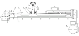
Fig. 1 is a front view of a simulated load loading device of a large chassis dynamometer according to an embodiment of the present invention;
fig. 2 is a top view of fig. 1.
The reference numbers are as follows:
the device comprises a supporting seat 1, a sliding seat 2, a suspension seat 3, a dragging wheel 4, a dragging belt 5, a dragging driving piece 6, a left roller 71, a right roller 72, a linear transmission piece 8, an elastic adjusting piece 9, a fixed seat 10 and a force detection piece 11;
a seat body 31, a carrier bar 32, and a support bar 33;
a linear screw 81 and a linear slider 82.
Detailed Description
The technical solutions in the embodiments of the present invention will be described clearly and completely with reference to the accompanying drawings in the embodiments of the present invention, and it is obvious that the described embodiments are only some embodiments of the present invention, not all embodiments. Based on the embodiments in the present invention, all other embodiments obtained by a person skilled in the art without creative work belong to the protection scope of the present invention.
In order to make the technical field better understand the solution of the present invention, the following detailed description of the present invention is provided with reference to the accompanying drawings and specific embodiments.
Referring to fig. 1 to 2, fig. 1 is a front view of an analog load loading device of a large chassis dynamometer according to an embodiment of the present invention; fig. 2 is a top view of fig. 1.
The embodiment of the utility model discloses analog load loading device of large-scale chassis dynamometer, include supporting seat 1, sliding seat 2, suspension seat 3, pull wheel 4, pull area 5 and pull driving piece 6.
The support base 1 is used to support other components, is placed parallel to the ground, and is fixed relative to the ground.
The sliding seat 2 can be slidably arranged on the supporting seat 1, the sliding seat 2 slides relative to the supporting seat 1, and the sliding seat 2 moves synchronously with the frame, so that the sliding seat 2 is always vertical to the frame, and the load loaded to the frame is always vertical. The sliding speed of the sliding seat 2 depends on the moving speed of the carriage.
The suspension seat 3 is arranged at the top of the sliding seat 2 and suspended at the bottom of the frame, and is used for driving the sliding seat 2 and the frame to move synchronously. Here, the top of the slide carriage 2 and the bottom of the carriage are subject to the current view of fig. 1.
The side of the suspension base 3 is provided with a towing wheel 4, and in this embodiment, the towing wheel 4 is specifically provided at the front and rear sides of the suspension base 3, where the front and rear directions are both based on the current view of fig. 2. The front side and the rear side of the suspension seat 3 are respectively provided with a dragging wheel 4, and each dragging wheel 4 is provided with a rolling bearing.
The first end of dragging area 5 is fixed in on supporting seat 1, and its second end is walked around and is dragged wheel 4 one-to-one, and the second end of dragging area 5 is walked around and is dragged wheel 4 back and link to each other with dragging driving piece 6, and it drags wheel 4 through dragging area 5 to drag suspension seat 3 to the realization, and then the realization drags the frame that links to each other with suspension seat 3, makes and drags wheel 4 and applys vertical load to the frame. In this embodiment, the utility model discloses specifically include two and pull area 5, two pull area 5 respectively with the suspension seat 3 around both sides pull wheel 4 and cooperate. The arrangement number of the dragging belts 5 is specifically set according to the number of the dragging wheels 4, and each dragging wheel 4 is correspondingly abutted to one dragging belt 5.
Drag driving piece 6 and set firmly in supporting seat 1, and drag wheel 4 and be located the bottom of sliding seat 2, make the trend of dragging area 5 be the triangle-shaped, conveniently drag area 5 and to dragging wheel 4 loading. The trailing drive 6 is preferably an electric motor, which may be a servo motor equipped with a gear reduction gearbox. Drag driving piece 6 and can also be pneumatic cylinder or cylinder, still can realize the utility model discloses a purpose.
When the device is used, the dragging driving piece 6 is started, one end of the dragging belt 5 is fixed, the other end of the dragging belt 5 is dragged, the dragging belt 5 applies acting force to the dragging wheel 4, and therefore the dragging wheel 4 simulates to apply vertical load to a frame; further, drag wheel 4 along with vehicle synchronous motion to make sliding seat 2 remove along supporting seat 1 under the effect of dragging wheel 4, make and drag area 5 and continuously apply vertical loading to the frame, the vertical load that the frame received depends on the output load who drags driving piece 6, need not frequently manually to increase the stone or change the loading packing box, artifical participation is little, intensity of labour reduces, and loading efficiency is higher. Therefore, the utility model provides a large-scale chassis dynamometer's analog load loading device can effectively promote loading efficiency.
The utility model discloses still include respectively rotationally locate the left gyro wheel 71 and the right gyro wheel 72 of the left and right sides in sliding seat 2 bottom. Based on the current view of fig. 1, the dragging belt 5 abuts against the bottom of the left roller 71 and the bottom of the right roller 72 respectively, the dragging belt 5 bypasses the left roller 71 and then continues to extend upwards until it winds around the dragging wheel 4, and the dragging belt 5 bypassing the dragging wheel 4 continues to extend downwards until it winds out from the bottom of the right roller 72, obviously, the arrangement of the left roller 71 and the right roller 72 can limit the dragging belt 5 to wind around or out of the dragging wheel 4, and the dragging belt 5 is effectively prevented from being separated from the dragging wheel 4. In this embodiment, the length of the left roller 71 is equal to the length of the right roller 72, and the lengths of the two rollers are set according to the distance between the two dragging bands 5 and the width of the dragging band 5, which is not limited in detail herein.
In order to further prevent the dragging belt 5 from separating from the left roller 71 or the right roller 72, a left mounting groove for mounting the left roller 71 is formed in the left side of the sliding seat 2, the left roller 71 is mounted in the left mounting groove through a rotating shaft, and two opposite side walls of the left mounting groove respectively abut against two ends of the left roller 71, so that the dragging belt 5 is prevented from separating from the left roller 71, and the reliability is improved; meanwhile, the right side of the sliding seat 2 is provided with a right mounting groove for mounting a right roller 72, the mounting mode of the right roller 72 is the same as that of the left roller 71, and two ends of the right roller 72 abut against two opposite sides of the right mounting groove respectively, so that the dragging belt 5 is prevented from being separated from the right roller 72, the dragging belt 5 is further prevented from being separated from the dragging wheel 4, and the reliability is further improved.
In this embodiment, the left roller 71 and the right roller 72 have the same outer diameter and are symmetrically installed on the left and right sides of the sliding seat 2. The vertical height between the left roller 71 and the support seat 1 and the vertical height between the right roller 72 and the support seat 1 are set according to the implementation situation, and the dragging belt 5 is guaranteed to be parallel to the support seat 1 as much as possible. The central axes of the dragging wheel 4, the left roller 71 and the right roller 72 are parallel, and the central axes of the dragging wheel, the left roller 71 and the right roller are distributed in a triangular shape.
The utility model discloses still including locating the second end that pulls area 5 and pulling the linear drive spare 8 between the driving piece 6, linear drive spare 8 is installed on supporting seat 1 to the adjustment is pulled area 5 and is applyed to the vertical load that pulls wheel 4, thereby the vertical load to the frame is applyed in the adjustment, makes vertical load can adjust according to the type and the operating condition of frame, avoids manual regulation vertical load, facilitates the use, and adaptability is better.
In this specific implementation, the linear transmission member 8 is specifically a screw-nut pair, and includes a linear screw 81 and a linear slider 82, the linear screw 81 is fixedly connected to the dragging driving member 6 through a coupling, the linear slider 82 is sleeved on the linear screw 81 and is fixedly connected to the second end of the dragging belt 5, and the linear screw 81 is in threaded connection with the linear slider 82. For making sharp slider 82 steadily slide, straight line driving medium 8 is still including locating between sharp slider 82 and the supporting seat 1 and T type slider or the T type spout of mutually supporting, and sharp slider 82 bottom is specifically located to T type slider, and the upper surface of supporting seat 1 is specifically located to T type spout to make T type spout guide sharp slider 82 along rectilinear movement, T type spout offsets along vertical and T type slider simultaneously, prescribes a limit to sharp slider 82 and breaks away from supporting seat 1, guarantees that sharp slider 82 reliably slides. Of course, the arrangement positions of the T-shaped sliding blocks or the T-shaped sliding grooves are interchanged, and the purpose of the utility model is not affected.
When the linear screw 81 is driven by the dragging driving piece 6 to rotate in the forward direction, the linear slider 82 moves to the right along the linear screw 81, the second end of the dragging belt 5 is far away from the first end of the dragging belt, and the vertical load applied to the dragging wheel 4 by the dragging belt 5 is increased; similarly, when the linear screw 81 is driven by the dragging driving element 6 to rotate reversely, the linear slider 82 moves leftwards along the linear screw 81, the second end of the dragging belt 5 is close to the first end of the dragging belt, and the vertical load applied to the dragging wheel 4 by the dragging belt 5 is reduced, so that the size of the vertical load applied to the dragging wheel 4 by the dragging belt 5 is adjusted.
Of course, the structure of the linear actuator 8 is not limited thereto.
In this embodiment, the suspension seat 3 comprises a seat body 31, two carrier bars 32 and a support bar 33, wherein the two carrier bars 32 penetrate through the seat body 31, and the carrier bars 32 are fixedly connected to the bottom of the vehicle frame. The support rod 33 penetrates through the seat body 31 and is used for supporting the dragging wheel 4, and the dragging wheel 4 is sleeved at two ends of the support rod 33. Specifically, the cross section of the seat body 31 is triangular, the two bearing rods 32 and the supporting rod 33 are distributed in a triangular shape, and the three are respectively distributed on each vertex angle of the cross section of the seat body 31, so that the structure of the suspension seat 3 is more stable, and the bearing capacity is stronger.
In this particular embodiment, the length of the two load bars 32 is equal to the inboard width of the vehicle frame, supported by the side rails of the vehicle. The width of the suspension seat 3 is smaller than the width of the inner side of the vehicle frame, so that the collision interference between the suspension seat 3 and the vehicle frame is prevented in the process of installing the bearing rod 32.
For making the sliding seat 2 remove along supporting seat 1 smoothly, the utility model discloses still including locating direction slide rail and the direction spout between sliding seat 2 and the supporting seat 1, direction slide rail and direction spout are mutually supported, and the direction slide rail is preferred to set firmly in the bottom of sliding seat 2, and the bottom of supporting seat 1 is preferably located to the direction spout, can also exchange the setting position of direction slide rail and direction spout certainly. The guide sliding rail may be a T-shaped sliding rail, and the guide sliding groove is correspondingly set as a T-shaped sliding groove.
The utility model discloses still including setting firmly in supporting seat 1 and with pull the elasticity regulating part 9 that area 5 links to each other to the regulation is pulled the elasticity degree of area 5, prevents to pull and takes 5 excessive laxs. The elastic adjustment element 9 is embodied as a bandage tightener whose working principle is specifically referred to the prior art and will not be described in detail here. Of course, the slack adjuster 9 may be a belt tensioner.
The utility model discloses still include fixing base 10, power detection piece 11, display and controller, wherein, fixing base 10 sets firmly in supporting seat 1 and links firmly mutually with the first end that pulls area 5, and fixing base 10 specifically is fixed in on the supporting seat 1 through fastening screw. The force detection member 11 is provided with a fixed seat 10 for detecting a current load applied to the fixed seat 10 by the towing belt 5. The force detection member 11 may be a force sensor, but is not limited thereto. The display is used for displaying the current load. The controller is connected with the force detection piece 11 and the display respectively, and the controller is used for controlling the display to display the current load according to the signal sent by the force detection piece 11, so that the tester can conveniently detect the vertical load value applied to the frame by the dragging belt 5 in real time, the use is more convenient, the loading efficiency is higher, and the loaded vertical load is more accurate.
The utility model discloses still include the alarm that links to each other with the controller, when power detection piece 11 detects current load and surpasss predetermined load scope, mean to pull and take 5 very easily to be broken or pull 6 work exceptions of driving piece, power detection piece 11 signals to controller this moment, and the controller starts the alarm, reminds testing personnel to carry out relative operation, for example shuts down etc. until removing the alarm to realize automatic alarm, work safe and reliable.
It should be noted that the controller includes a signal receiving portion, a signal determining portion and a signal transmitting portion, the signal receiving portion is used for receiving the electrical signal transmitted by the force detecting member 11, the signal determining portion is electrically connected to the receiving portion so that the signal determining portion is used for determining whether the signal received by the receiving portion is the trigger signal, and the signal transmitting portion is electrically connected to the signal determining portion so that the signal transmitting portion transmits the determination signal generated by the signal determining portion to the alarm. The specific arrangement mode of the signal receiving part, the signal judging part and the signal sending part can refer to the prior art; in the utility model, only the application scene of the three is changed, but not the substantial improvement is carried out.
Obviously, the controller with the structure is widely applied to the existing automatic control equipment, such as an MCU, a DSP or a single chip microcomputer. The key point of the utility model is that the controller combines the force detection piece 11 and the alarm.
The above detailed description is made on the analog load loading device of the large chassis dynamometer provided by the present invention, and the specific examples are applied herein to explain the principle and the implementation manner of the present invention, and the description of the above embodiments is only used to help understanding the method and the core idea of the present invention; meanwhile, for the general technical personnel in the field, according to the idea of the present invention, there are changes in the specific implementation and application scope, to sum up, the content of the present specification should not be understood as the limitation of the present invention.
Claims (10)
1. A simulation load loading device of a large chassis dynamometer is characterized by comprising:
a support base (1);
the sliding seat (2) is slidably arranged on the supporting seat (1) and is used for synchronously moving along with the frame;
the suspension seat (3) is arranged at the top of the sliding seat (2) and is suspended on the frame, and a dragging wheel (4) is arranged on the side surface of the suspension seat (3);
the first ends of the dragging belts are fixed on the supporting seat (1), and the second ends of the dragging belts wrap around the dragging wheels (4) in a one-to-one correspondence manner;
and the dragging driving piece (6) is fixedly connected with the second ends of all the dragging belts (5), fixed on the supporting seat (1) and used for dragging the dragging wheel (4) through the dragging belts (5) so as to enable the dragging wheel (4) to apply vertical load to the frame.
2. The simulated load loading apparatus of a large chassis dynamometer according to claim 1, further comprising:
the left roller (71) and the right roller (72) are respectively and rotatably arranged at the left side and the right side of the bottom of the sliding seat (2) and are used for limiting the dragging belt (5) to wind around or out of the dragging wheel (4) so as to prevent the dragging belt (5) from being separated from the dragging wheel (4).
3. The simulated load loading apparatus of a large chassis dynamometer according to claim 1, further comprising:
the linear transmission piece (8) is installed between the second end of the dragging belt (5) and the dragging driving piece (6) and is used for adjusting the vertical load applied to the dragging wheel (4) by the dragging belt (5).
4. The simulated load loading apparatus of a large chassis dynamometer according to claim 3, wherein the linear transmission (8) includes:
a linear screw (81) fixedly connected with the dragging driving piece (6);
the linear sliding block (82) is sleeved on the linear screw (81), is fixedly connected with the second end of the dragging belt (5), and is used for driving the second end of the dragging belt (5) to move along the supporting seat (1) when the linear screw (81) rotates;
the T-shaped sliding block or the T-shaped sliding groove is arranged between the linear sliding block (82) and the supporting seat (1), is matched with the supporting seat (1), and is used for guiding the linear sliding block (82) to move and limiting the linear sliding block (82) to be separated from the supporting seat (1).
5. The simulated load loading device of the large chassis dynamometer according to any one of claims 1-4, wherein the suspension seat (3) includes a seat body (31), two bearing rods (32) passing through the seat body (31) and used for being fixed to the bottom of the vehicle frame, and a support rod (33) passing through the seat body (31) and used for supporting the dragging wheel (4); the two bearing rods (32) and the supporting rod (33) are distributed in a triangular shape.
6. The simulated load loading apparatus of the large chassis dynamometer according to any one of claims 1 through 4, further comprising:
the guide sliding rail and the guide sliding groove are arranged between the sliding seat (2) and the supporting seat (1), are matched with each other and are used for guiding the sliding seat (2) to move relative to the supporting seat (1).
7. The simulated load loading apparatus of the large chassis dynamometer according to any one of claims 1 through 4, further comprising:
and the tightness adjusting piece (9) is fixedly arranged on the supporting seat (1), is connected with the dragging belt (5) and is used for adjusting the tightness degree of the dragging belt (5).
8. The simulated load loading unit of a large chassis dynamometer according to claim 7, characterized in that said slack adjuster (9) is embodied as a belt tightener.
9. The simulated load loading apparatus of the large chassis dynamometer according to any one of claims 1 through 4, further comprising:
the fixed seat (10) is fixedly arranged on the supporting seat (1) and is fixedly connected with the first end of the dragging belt (5);
a force detection member (11) provided with the fixed seat (10) and used for detecting the current load applied to the fixed seat (10) by the dragging belt (5);
a display for displaying the current load;
and the controller is connected with the force detection piece (11) and the display and is used for controlling the display to display the current load according to a signal sent by the force detection piece (11).
10. The simulated load loading device of large chassis dynamometer according to claim 9, further comprising an alarm connected to said controller, said controller activating said alarm when said current load exceeds a predetermined load range according to a signal from said force detector (11).
Priority Applications (1)
| Application Number | Priority Date | Filing Date | Title |
|---|---|---|---|
| CN202020145366.9U CN211262729U (en) | 2020-01-22 | 2020-01-22 | Analog load loading device of large chassis dynamometer |
Applications Claiming Priority (1)
| Application Number | Priority Date | Filing Date | Title |
|---|---|---|---|
| CN202020145366.9U CN211262729U (en) | 2020-01-22 | 2020-01-22 | Analog load loading device of large chassis dynamometer |
Publications (1)
| Publication Number | Publication Date |
|---|---|
| CN211262729U true CN211262729U (en) | 2020-08-14 |
Family
ID=71987220
Family Applications (1)
| Application Number | Title | Priority Date | Filing Date |
|---|---|---|---|
| CN202020145366.9U Active CN211262729U (en) | 2020-01-22 | 2020-01-22 | Analog load loading device of large chassis dynamometer |
Country Status (1)
| Country | Link |
|---|---|
| CN (1) | CN211262729U (en) |
-
2020
- 2020-01-22 CN CN202020145366.9U patent/CN211262729U/en active Active
Similar Documents
| Publication | Publication Date | Title |
|---|---|---|
| DE60110387T2 (en) | ROLLER TEST BENCH AND METHOD FOR TESTING VEHICLES | |
| CN101979987B (en) | Vehicle brake detection table with acceleration simulation function | |
| CN101886981A (en) | Adjustable-axle distance roller device | |
| CN103033372B (en) | A kind of controllable wheel traction of slippage rate and adhesion property test device | |
| CN211262729U (en) | Analog load loading device of large chassis dynamometer | |
| US3345865A (en) | Vehicle testing device | |
| CN205919969U (en) | Car loading brake performance detection device | |
| CN102323066A (en) | Crawler chassis test stand | |
| CN110132755B (en) | Bending-resistant wire tester | |
| CN201697740U (en) | Device for measuring braking force of low-speed and high-torque engineering vehicle | |
| US5402674A (en) | Method and apparatus for automatically restraining a vehicle on a test stand | |
| CN111089735A (en) | Analog load loading device of large chassis dynamometer | |
| CN108535027B (en) | Static side-turning stability test bed for tractor | |
| CN201514325U (en) | Endless-track type rotary drum test platform | |
| CN209745692U (en) | Slide rail test machine | |
| JP4805190B2 (en) | Chassis dynamometer vehicle fixing device | |
| CN209922769U (en) | Winch compensation device | |
| CN213022327U (en) | Test bench for self-propelled rail orchard conveyor | |
| EP0772035B1 (en) | Plate circulator and force measuring apparatus | |
| CN208715441U (en) | A kind of oblique unwheeling of comb slideway is synchronous and load balancing monitors adjustment system | |
| CN208547484U (en) | The adjustable anti-force type automobile brake testing bench of a kind of wheelbase | |
| CN201532314U (en) | Brake load type wheel testing device | |
| JP2993312B2 (en) | Roll characteristic test equipment for vehicles | |
| CN116923232B (en) | Double-vehicle linkage transportation system and method | |
| CN211493791U (en) | Vehicle-mounted hoisting equipment suitable for special automobile |
Legal Events
| Date | Code | Title | Description |
|---|---|---|---|
| GR01 | Patent grant | ||
| GR01 | Patent grant |