CN211221621U - Die carrier that can dismantle fast - Google Patents
Die carrier that can dismantle fast Download PDFInfo
- Publication number
- CN211221621U CN211221621U CN201921526174.6U CN201921526174U CN211221621U CN 211221621 U CN211221621 U CN 211221621U CN 201921526174 U CN201921526174 U CN 201921526174U CN 211221621 U CN211221621 U CN 211221621U
- Authority
- CN
- China
- Prior art keywords
- disc
- clamping
- top end
- strip
- connecting rod
- Prior art date
- Legal status (The legal status is an assumption and is not a legal conclusion. Google has not performed a legal analysis and makes no representation as to the accuracy of the status listed.)
- Active
Links
Images


Landscapes
- Moulds For Moulding Plastics Or The Like (AREA)
Abstract
The utility model discloses a die carrier that can dismantle fast, including base and mould, the draw-in groove has been seted up in the bottom four corners of mould, and the inner chamber of draw-in groove is pegged graft and is had some on the top of clamping mechanism, clamping mechanism's bottom mounting has the base, the outer wall top interference fit of pivot has the disc, and the top rear side of disc all rotates the one end that is linked with the connecting rod with the top outside of disc, the other end of connecting rod cup joints on the cylinder that corresponds with it, cylindrical top is provided with the chassis, and the top central point on chassis puts and is provided with the card strip, the top that the casing was extended on the top of card strip is pegged graft in the draw-in groove. This die carrier that can dismantle fast can dismantle the change mould fast according to different demands, easy operation, greatly reduced the probability that the part damaged the deformation, need not worry operation details, alleviate staff's burden, improve whole work efficiency, make later stage use more convenient and fast.
Description
Technical Field
The utility model relates to the technical field, specifically be a die carrier that can dismantle fast.
Background
The application of present mould relates to every product, like car, space flight, daily necessities, electrical apparatus communication, medical product equipment etc., as long as the product that is a large amount all can use mould production, and the die carrier is the inseparable part of mould, however in the actual operation in-process, because the demand is different, consequently need dismantle and change to the mould of difference, but traditional die carrier dismantles too loaded down with trivial details, still pay attention to the details in the dismantlement process simultaneously, avoid causing damage or deformation to the spare part in the change process, and do the mark when dismantling to the spare part that has the installation direction requirement, waste time even causes the damage of part when avoiding installing, the labour is makeed, increase worker's burden reduces work efficiency again.
SUMMERY OF THE UTILITY MODEL
An object of the utility model is to provide a die carrier that can dismantle fast to solve the problem that proposes in the above-mentioned background art.
In order to achieve the above object, the utility model provides a following technical scheme: a die carrier capable of being quickly disassembled comprises a base and a die, wherein clamping grooves are formed in four corners of the bottom end of the die, a part of the top end of a clamping mechanism is inserted into an inner cavity of each clamping groove, and the base is fixed at the bottom end of the clamping mechanism;
the clamping mechanism comprises a shell, a guide rod, a sliding block, a cylinder, a spring, a rotating shaft, a rotating disc, a gear, a disc, a clamping strip, a connecting rod and a chassis;
guide rods are fixed on the front side and the rear side of an inner cavity of the shell in the left-right direction, sliders are sleeved at the left end and the right end of an outer wall of each guide rod, a cylinder is fixed at the top center position of each slider, springs are sleeved on the outer wall of each guide rod, the left end and the right end of each spring are fixed on the inner sides of the sliders respectively, a rotating shaft is symmetrically and rotatably connected at the left end and the right end of the inner cavity bottom center position of the shell through bearings, a rotating disc is fixed at the bottom end, located on the right side, of the rotating shaft, extending out of the bottom end of the shell, a gear is in interference fit with the outer wall center position of the rotating disc, a disc is in interference fit with the top end of the outer wall of the rotating shaft, one end of a connecting rod is rotatably connected with the outer side of the top end of the disc, the other end of the connecting, the top end of the clamping strip extends out of the top end of the shell and is inserted into the clamping groove.
Preferably, the clamping groove is L-shaped, and the size of the inner cavity of the clamping groove is larger than that of the top end of the clamping strip.
Preferably, the overall size of the disc is smaller than the overall size of the gear.
Preferably, the shape of the clamping strip is L-shaped, and the top end of the clamping strip inclines towards the outer bottom end.
Compared with the prior art, the beneficial effects of the utility model are that: this die carrier that can dismantle fast, when the in-service use, counter-clockwise turning carousel, through the pivot, under the cooperation of gear and disc, can make four connecting rods spacing down in the cooperation of guide arm and slider, to inboard horizontal migration, and then drive the card strip and remove the fixed to the mould, can dismantle the change mould fast according to different demands, and easy operation, greatly reduced the probability that the part damaged the deformation, need not worry operation details, alleviate staff's burden, improve whole work efficiency, make later stage use more convenient and fast.
Drawings
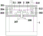
Fig. 1 is a top sectional view of the locking mechanism of the present invention;
fig. 2 is a right side sectional view of the present invention;
fig. 3 is a front sectional view of the present invention.
In the figure: 1. the clamping mechanism comprises a base, 2, a clamping mechanism, 201, a shell, 202, a guide rod, 203, a sliding block, 204, a cylinder, 205, a spring, 206, a rotating shaft, 207, a rotating disc, 208, a gear, 209, a disc, 210, a clamping strip, 211, a connecting rod, 212, a chassis, 3, a mould, 4 and a clamping groove.
Detailed Description
The technical solutions in the embodiments of the present invention will be described clearly and completely with reference to the accompanying drawings in the embodiments of the present invention, and it is obvious that the described embodiments are only some embodiments of the present invention, not all embodiments. Based on the embodiments in the present invention, all other embodiments obtained by a person skilled in the art without creative work belong to the protection scope of the present invention.
Referring to fig. 1-3, the present invention provides a mold frame with a quick detachable structure: a die carrier capable of being rapidly disassembled comprises a base 1 and a die 3, wherein four corners of the bottom end of the die 3 are provided with clamping grooves 4, a part of the top end of a clamping mechanism 2 is inserted into an inner cavity of each clamping groove 4, and the base 1 is fixed at the bottom end of the clamping mechanism 2;
the clamping mechanism 2 comprises a shell 201, a guide rod 202, a sliding block 203, a cylinder 204, a spring 205, a rotating shaft 206, a rotating disc 207, a gear 208, a disc 209, a clamping strip 210, a connecting rod 211 and a bottom disc 212;
Preferably, the shape of the slot 4 is "L" and the inner cavity of the slot 4 is larger than the size of the top end of the clip strip 210, so that the clip strip 210 can enter the inner cavity of the slot 4, and the clip strip 210 can fix and detach the mold 3.
Preferably, the overall size of the disc 209 is smaller than the overall size of the gears 208, so that the disc 209 is prevented from being too large to affect the meshing rotation of the two gears 208.
Preferably, the shape of the clip strip 210 is "L", and the top end of the clip strip 210 is inclined to the outer side and the bottom end, when the mold 3 is sleeved on the clip strip 210 from the top to the bottom, the direction of the clip strip 210 is changed under the action of the inclined surface of the clip strip 210, so that the clip strip 210 automatically moves to the inner side to fix the mold 3.
The detailed connection means is a technique known in the art, and the following mainly describes the working principle and process, and the specific operation is as follows.
When the mold 3 needs to be quickly disassembled, the rotating disc 207 is rotated counterclockwise, the rotating shaft 206 on the rotating disc 207 drives the gear 208 and the disc 209 to rotate together, because the two gears 208 are meshed and connected, when the gear 208 on the right side rotates counterclockwise, the gear 208 on the left side, the rotating shaft 206 and the disc 209 can be driven to rotate clockwise simultaneously, so that the connecting rods 211 on the two discs 209 can drive the sliding block 203 to move horizontally inwards under the limit of the guide rod 202 along with the rotation of the two gears 208, the spring 205 is pressed inwards, the chassis 212 also moves horizontally inwards along with the cylinder 204 on the sliding block 203, the clamping strips 210 on the chassis 212 release the fixation of the mold 3, at the moment, the mold 3 can be disassembled by taking out the mold 3 upwards, when another mold needs to be replaced, the other mold needing to be replaced is placed downwards at the top end of the shell 201, card strip 210 is touched to new mould, makes card strip 210 slide to the inboard, when the top of new mould bottom laminating casing 201 completely, with the help of spring 205's elasticity, can make card strip 210 get into the inner chamber of draw-in groove 4 and then fix new mould, reaches and to dismantle installation mould 3 as required at any time, and easy operation need not to do the record in advance, alleviates staff's burden, and labour saving and time saving improves work efficiency, is favorable to promoting.
In the description of the present invention, it is to be understood that the terms "central position", "inner chamber", "outer wall", "top end", "one end", "the other end", "a portion", and the like, indicate an orientation or positional relationship based on that shown in the drawings, merely for convenience of description and simplicity of description, and do not indicate or imply that the device or element being referred to must have a particular orientation, be constructed and operated in a particular orientation; also, unless expressly stated or limited otherwise, the terms "disposed," "secured," "plugged," "interference fit," "sleeved," and the like are to be construed broadly, e.g., as meaning a fixed connection, a removable connection, or an integral part; can be mechanically or electrically connected; they may be directly connected or indirectly connected through an intermediate medium, and may be connected through the inside of two elements or in an interaction relationship between two elements, unless otherwise specifically defined, and the specific meaning of the above terms in the present invention will be understood by those skilled in the art according to specific situations.
Although embodiments of the present invention have been shown and described, it will be appreciated by those skilled in the art that changes, modifications, substitutions and alterations can be made in these embodiments without departing from the principles and spirit of the invention, the scope of which is defined in the appended claims and their equivalents.
Claims (4)
1. The utility model provides a but quick dismantlement's die carrier, includes base (1) and mould (3), its characterized in that: clamping grooves (4) are formed in four corners of the bottom end of the die (3), a part of the top end of the clamping mechanism (2) is inserted into an inner cavity of each clamping groove (4), and a base (1) is fixed at the bottom end of the clamping mechanism (2);
the clamping mechanism (2) comprises a shell (201), a guide rod (202), a sliding block (203), a cylinder (204), a spring (205), a rotating shaft (206), a rotating disc (207), a gear (208), a disc (209), a clamping strip (210), a connecting rod (211) and a chassis (212);
both sides all are fixed with guide arm (202) along left right direction around the inner chamber of casing (201), both ends have all been cup jointed slider (203) about the outer wall of guide arm (202), and the top central point of slider (203) puts and is fixed with cylinder (204), spring (205) cup joint on the outer wall of guide arm (202), and the inboard at slider (203) is fixed respectively at both ends about spring (205), the inner chamber bottom central point of casing (201) puts and all rotates through the bearing symmetry about both ends and connect pivot (206), and the bottom mounting that is located pivot (206) bottom on right side and extends casing (201) has carousel (207), the outer wall central point interference fit of carousel (207) has gear (208), and two gear (208) meshing are connected, the outer wall top interference fit of pivot (206) has disc (209), and the top rear side of disc (209) and the top outside of disc (209) all rotate and link a of connecting rod (211) outside The other end of the connecting rod (211) is sleeved on the corresponding cylinder (204), a base plate (212) is arranged at the top end of the cylinder (204), a clamping strip (210) is arranged at the center of the top end of the base plate (212), and the top end of the clamping strip (210) extends out of the top end of the shell (201) and is inserted into the clamping groove (4).
2. A quickly demountable formwork in accordance with claim 1 wherein: the clamping groove (4) is L-shaped, and the size of the inner cavity of the clamping groove (4) is larger than the size of the top end of the clamping strip (210).
3. A quickly demountable formwork in accordance with claim 1 wherein: the overall size of the disc (209) is smaller than the overall size of the gear (208).
4. A quickly demountable formwork in accordance with claim 1 wherein: the shape of card strip (210) is "L" shape, and the top of card strip (210) inclines to outside bottom.
Priority Applications (1)
| Application Number | Priority Date | Filing Date | Title |
|---|---|---|---|
| CN201921526174.6U CN211221621U (en) | 2019-09-14 | 2019-09-14 | Die carrier that can dismantle fast |
Applications Claiming Priority (1)
| Application Number | Priority Date | Filing Date | Title |
|---|---|---|---|
| CN201921526174.6U CN211221621U (en) | 2019-09-14 | 2019-09-14 | Die carrier that can dismantle fast |
Publications (1)
| Publication Number | Publication Date |
|---|---|
| CN211221621U true CN211221621U (en) | 2020-08-11 |
Family
ID=71922047
Family Applications (1)
| Application Number | Title | Priority Date | Filing Date |
|---|---|---|---|
| CN201921526174.6U Active CN211221621U (en) | 2019-09-14 | 2019-09-14 | Die carrier that can dismantle fast |
Country Status (1)
| Country | Link |
|---|---|
| CN (1) | CN211221621U (en) |
-
2019
- 2019-09-14 CN CN201921526174.6U patent/CN211221621U/en active Active
Similar Documents
| Publication | Publication Date | Title |
|---|---|---|
| CN209793293U (en) | Statue of buddha base grinding device for statue of buddha sculpture | |
| CN211221621U (en) | Die carrier that can dismantle fast | |
| CN213519019U (en) | Marketing is with multi-functional propaganda device | |
| CN214981714U (en) | Bamboo plywood hot press | |
| CN216328814U (en) | Circular knife machine with dust removal function | |
| CN216574645U (en) | Magnetic core belt cleaning device convenient to screening mechanism | |
| CN214793025U (en) | Product outline acquisition device for industrial design | |
| CN114598084A (en) | Fixing device for robot based on voice interaction venue | |
| CN207386631U (en) | A kind of steel plate positional punch equipment | |
| CN211089733U (en) | Intelligent monitoring camera for conventional instrument data acquisition of traditional transformer substation | |
| CN209272165U (en) | A kind of dedicated unwrapping wire component of wire drawing machine | |
| CN113927064A (en) | Drilling device for pipe body | |
| CN208160585U (en) | A kind of dust catcher noise-dampened motor | |
| CN214963433U (en) | Engineering management design platform | |
| CN216607645U (en) | Automatic laser engraving machine for labels | |
| CN211459611U (en) | Display stand with LED screen convenient to install | |
| CN217875014U (en) | High-precision positioning-based multi-position deployment shooting system in venue | |
| CN218518466U (en) | Glass silk screen printing positioning jig | |
| CN214432135U (en) | Support for dress designing | |
| CN219938724U (en) | Big data storage server | |
| CN209251734U (en) | A kind of calcium tablet molding machine | |
| CN213276997U (en) | Multimedia display equipment convenient to move | |
| CN218964598U (en) | Portable small-size pushing and pressing machine for bearing | |
| CN214226156U (en) | Video teaching device based on thing networking | |
| CN214410611U (en) | LED billboard for building engineering management |
Legal Events
| Date | Code | Title | Description |
|---|---|---|---|
| GR01 | Patent grant | ||
| GR01 | Patent grant |