CN211221249U - Mould is used in production of prestressed concrete pile - Google Patents
Mould is used in production of prestressed concrete pile Download PDFInfo
- Publication number
- CN211221249U CN211221249U CN201921904671.5U CN201921904671U CN211221249U CN 211221249 U CN211221249 U CN 211221249U CN 201921904671 U CN201921904671 U CN 201921904671U CN 211221249 U CN211221249 U CN 211221249U
- Authority
- CN
- China
- Prior art keywords
- base
- fixedly connected
- concrete pile
- mould body
- prestressed concrete
- Prior art date
- Legal status (The legal status is an assumption and is not a legal conclusion. Google has not performed a legal analysis and makes no representation as to the accuracy of the status listed.)
- Active
Links
Images


Abstract
The utility model discloses a mould is used in production of prestressed concrete pile, including base, lower mould body, supporting mechanism, go up mould body and form removal mechanism, the top of base is provided with the lower mould body, the top of bottom and the position that corresponds the lower mould body are provided with supporting mechanism, supporting mechanism corresponds the last mould body of the fixed position connection of lower mould body, the left and right sides at base top and the position that corresponds the lower mould body all are provided with form removal mechanism, the lower mould body includes framed, side form, installation piece and mounting groove, the bottom of framed and the top fixed connection of base. The utility model discloses a mutually supporting between base, lower mould body, supporting mechanism and the last mould body has realized a mould for prestressed concrete pile production, and the convenience is demolished fashioned concrete pile to avoided the form removal in-process because workman's error makes the product receive the problem that the damage caused economic loss.
Description
Technical Field
The utility model relates to a concrete pile technical field specifically is a mould is used in production of prestressed concrete pile.
Background
Concrete pile is the stake of making with concrete (including ordinary reinforced concrete, prestressed concrete), and common concrete pile is sent into the dedicated mould through the distributing pipe concrete thick liquid when production in, and common mould generally divide into upper and lower mould, consequently can only get rid of last mould when form removal, then dismantles the product, because the product adsorbs easily in the die cavity, so make the product receive the damage because workman's error easily at form removal in-process to cause certain economic loss.
SUMMERY OF THE UTILITY MODEL
In order to solve the problem the utility model provides a mould is used in production of prestressed concrete pile.
In order to achieve the above object, the utility model provides a following technical scheme: a mould for producing a prestressed concrete pile comprises a base, a lower mould body, a supporting mechanism, an upper mould body and a mould removing mechanism, wherein the lower mould body is arranged at the top of the base, the supporting mechanism is arranged at the top of the bottom and corresponds to the position of the lower mould body, the upper mould body is fixedly connected with the supporting mechanism corresponding to the position of the lower mould body, and the mould removing mechanisms are arranged at the left side and the right side of the top of the base and correspond to the positions of the lower mould body;
the lower die body comprises a die frame, side dies, mounting blocks and mounting grooves, the bottom of the die frame is fixedly connected with the top of the base, the side dies are arranged on the left side and the right side of the die frame, the mounting grooves are formed in the bottoms of the left side and the right side of the die frame, the mounting blocks matched with the mounting grooves are arranged on the side dies close to one side of the die frame and correspond to the mounting grooves, and one side of the mounting blocks close to the mounting grooves penetrates through the mounting grooves and extends into the mounting grooves;
the supporting mechanism comprises two supporting plates, a cross rod, an air cylinder and a connecting frame, the two supporting plates are symmetrically arranged on the front side and the rear side of the top of the base, the tops of the two supporting plates are fixedly connected through the cross rod, the air cylinder is fixedly arranged at the middle point of the top of the cross rod, the output end of the air cylinder penetrates through the cross rod and extends to the outside of the cross rod to be fixedly connected with the connecting frame, and the bottom of the connecting frame is fixedly connected with the upper die body;
the form removal mechanism includes spout, driving motor, threaded rod and screw thread piece, the spout has all been seted up to the left and right sides at base top, the equal fixed mounting in the position of the left and right sides of base and corresponding spout has driving motor, fixedly connected with threaded rod on driving motor's the output shaft, one side that the threaded rod is close to the spout runs through the spout and extends to inside it, is located the threaded rod surface threaded connection of spout inside has rather than the screw thread piece of looks adaptation.
Preferably, the upper die body is provided with a material injection pipe.
Preferably, the top of side form has seted up the seal groove, go up the bottom of mould body and correspond the position fixedly connected with of seal groove rather than the sealed pad of looks adaptation.
Preferably, the surface of the threaded rod and the position corresponding to the side wall of the sliding groove are provided with limiting bearings.
Preferably, the top of the thread block is fixedly connected with the bottom of the side die.
Compared with the prior art, the beneficial effects of the utility model are as follows:
1. the utility model discloses a mutually supporting between base, lower mould body, supporting mechanism and the last mould body has realized a mould for prestressed concrete pile production, and the convenience is demolished fashioned concrete pile to avoided the form removal in-process because workman's error makes the product receive the problem that the damage caused economic loss.
2. The utility model discloses a setting up the seal groove and sealed the pad and making go up mould body and lower mould body leakproofness better when compound die.
Drawings
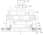
FIG. 1 is a structural section view in elevation of the present invention;
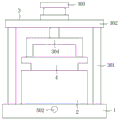
FIG. 2 is a schematic left side view of the present invention;
FIG. 3 is an enlarged view of a portion of A-A of FIG. 1 according to the present invention;
fig. 4 is a schematic structural diagram of a left side view of the side mold of the present invention.
In the figure: the die comprises a base 1, a lower die body 2, a supporting mechanism 3, an upper die body 4, a die detaching mechanism 5, a die frame 201, side dies 202, a die mounting block 203, a mounting groove 204, a supporting plate 301, a cross rod 302, an air cylinder 303, a connecting frame 304, a sliding groove 501, a driving motor 502, a threaded rod 503, a threaded block 504, a sealing groove 6 and a sealing gasket 7.
Detailed Description
The technical solutions in the embodiments of the present invention will be described clearly and completely with reference to the accompanying drawings in the embodiments of the present invention, and it is obvious that the described embodiments are only some embodiments of the present invention, not all embodiments. Based on the embodiments in the present invention, all other embodiments obtained by a person skilled in the art without creative work belong to the protection scope of the present invention.
Referring to fig. 1-4, a mold for producing a prestressed concrete pile includes a base 1, a lower mold body 2, a supporting mechanism 3, an upper mold body 4 and a demolding mechanism 5, wherein the lower mold body 2 is disposed on the top of the base 1, the supporting mechanism 3 is disposed on the top of the bottom 1 and corresponding to the lower mold body 2, the upper mold body 4 is fixedly connected to the supporting mechanism 3 corresponding to the lower mold body 2, a material injection pipe is disposed on the upper mold body 4, and the demolding mechanisms 5 are disposed on the left and right sides of the top of the base 1 and corresponding to the lower mold body 2.
The supporting mechanism 3 comprises two supporting plates 301, a cross rod 302, a cylinder 303 and a connecting frame 304, the number of the supporting plates 301 is two, the supporting plates are symmetrically arranged on the front side and the rear side of the top of the base 1, the tops of the two supporting plates 301 are fixedly connected with each other through the cross rod 302, the cylinder 303 is fixedly arranged at the middle point of the top of the cross rod 302, the output end of the cylinder 303 penetrates through the cross rod 302 and extends to the connecting frame 304, and the bottom of the connecting frame 304 is fixedly connected with the upper die body 4.
The form removing mechanism 5 comprises a sliding groove 501, a driving motor 502, a threaded rod 503 and a threaded block 504, the sliding groove 501 is arranged on the left side and the right side of the top of the base 1, the driving motor 502 is fixedly arranged on the left side and the right side of the base 1 and corresponding to the position of the sliding groove 501, the threaded rod 503 is fixedly connected to the output shaft of the driving motor 502, one side of the threaded rod 503 close to the sliding groove 501 penetrates through the sliding groove 501 and extends into the sliding groove 501, a limit bearing is arranged on the surface of the threaded rod 503 and corresponding to the side wall of the sliding groove 501, the threaded block 504 matched with the threaded rod 503 is in threaded connection with the surface of the sliding groove 501, the top of the threaded block 504 is fixedly connected with the bottom of the side form 202, through mutual matching of the base 1, the lower die body 2, the supporting mechanism 3 and the upper die body 4, a mold for producing, thereby avoiding the problem of economic loss caused by the damage of the product due to the error of workers in the form removal process.
During the use, when the mould needs to be demolished, thereby only need drive through cylinder 303 and go up mould body 4 rebound and break away from lower mould body 2, then open driving motor 502, make it drive threaded rod 503 and rotate to under the screw action of screw piece 504, make screw piece 504 can drive side form 202 and remove to the direction of keeping away from framed 201, thereby the convenience is demolishd the concrete pile on framed 201.
In summary, the following steps: this mould is used in production of prestressed concrete pile has solved the problem that the background art mentioned through setting up base 1, lower mould body 2, supporting mechanism 3 and last mould body 4.
Although embodiments of the present invention have been shown and described, it will be appreciated by those skilled in the art that changes, modifications, substitutions and alterations can be made in these embodiments without departing from the principles and spirit of the invention, the scope of which is defined in the appended claims and their equivalents.
Claims (5)
1. The utility model provides a mould is used in production of prestressed concrete pile, includes base (1), lower mould body (2), supporting mechanism (3), goes up mould body (4) and form removal mechanism (5), its characterized in that: a lower die body (2) is arranged at the top of the base (1), a supporting mechanism (3) is arranged at the top of the base (1) and at a position corresponding to the lower die body (2), an upper die body (4) is fixedly connected to the supporting mechanism (3) at a position corresponding to the lower die body (2), and form removing mechanisms (5) are arranged at the left side and the right side of the top of the base (1) and at positions corresponding to the lower die body (2);
the lower die body (2) comprises a die frame (201), side dies (202), mounting blocks (203) and mounting grooves (204), the bottom of the die frame (201) is fixedly connected with the top of the base (1), the side dies (202) are arranged on the left side and the right side of the die frame (201), the mounting grooves (204) are formed in the bottoms of the left side and the right side of the die frame (201), the mounting blocks (203) matched with the mounting grooves (204) are formed in positions, corresponding to the mounting grooves (204), of the side dies (202), one sides, close to the mounting grooves (204), of the mounting blocks (203) penetrate through the mounting grooves (204) and extend into the mounting grooves (204);
the supporting mechanism (3) comprises two supporting plates (301), a cross rod (302), air cylinders (303) and connecting frames (304), the two supporting plates (301) are symmetrically arranged on the front side and the rear side of the top of the base (1), the tops of the two supporting plates (301) are fixedly connected through the cross rod (302), the air cylinders (303) are fixedly arranged at the middle point of the top of the cross rod (302), the output ends of the air cylinders (303) penetrate through the cross rod (302) and extend to the outside of the cross rod (302) to be fixedly connected with the connecting frames (304), and the bottoms of the connecting frames (304) are fixedly connected with the upper die body (4);
the utility model discloses a form removal mechanism (5) is including spout (501), driving motor (502), threaded rod (503) and screw block (504), spout (501) have all been seted up to the left and right sides at base (1) top, the equal fixed mounting in position of the left and right sides of base (1) and corresponding spout (501) has driving motor (502), fixedly connected with threaded rod (503) on the output shaft of driving motor (502), one side that threaded rod (503) are close to spout (501) runs through spout (501) and extends to inside it, is located inside threaded rod (503) surface threaded connection of spout (501) have rather than screw block (504) of looks adaptation.
2. The mold for producing a prestressed concrete pile according to claim 1, wherein: and the upper die body (4) is provided with a material injection pipe.
3. The mold for producing a prestressed concrete pile according to claim 1, wherein: sealing groove (6) have been seted up at the top of side form (202), go up the position fixedly connected with of the bottom of mould body (4) and corresponding sealing groove (6) rather than sealed pad (7) of looks adaptation.
4. The mold for producing a prestressed concrete pile according to claim 1, wherein: and a limiting bearing is arranged on the surface of the threaded rod (503) and at a position corresponding to the side wall of the sliding groove (501).
5. The mold for producing a prestressed concrete pile according to claim 1, wherein: the top of the thread block (504) is fixedly connected with the bottom of the side die (202).
Priority Applications (1)
| Application Number | Priority Date | Filing Date | Title |
|---|---|---|---|
| CN201921904671.5U CN211221249U (en) | 2019-11-07 | 2019-11-07 | Mould is used in production of prestressed concrete pile |
Applications Claiming Priority (1)
| Application Number | Priority Date | Filing Date | Title |
|---|---|---|---|
| CN201921904671.5U CN211221249U (en) | 2019-11-07 | 2019-11-07 | Mould is used in production of prestressed concrete pile |
Publications (1)
| Publication Number | Publication Date |
|---|---|
| CN211221249U true CN211221249U (en) | 2020-08-11 |
Family
ID=71914166
Family Applications (1)
| Application Number | Title | Priority Date | Filing Date |
|---|---|---|---|
| CN201921904671.5U Active CN211221249U (en) | 2019-11-07 | 2019-11-07 | Mould is used in production of prestressed concrete pile |
Country Status (1)
| Country | Link |
|---|---|
| CN (1) | CN211221249U (en) |
Cited By (1)
| Publication number | Priority date | Publication date | Assignee | Title |
|---|---|---|---|---|
| CN115070910A (en) * | 2022-06-21 | 2022-09-20 | 湖州天逸预制构件有限公司 | Be used for prefabricated plate preparation template installation device |
-
2019
- 2019-11-07 CN CN201921904671.5U patent/CN211221249U/en active Active
Cited By (2)
| Publication number | Priority date | Publication date | Assignee | Title |
|---|---|---|---|---|
| CN115070910A (en) * | 2022-06-21 | 2022-09-20 | 湖州天逸预制构件有限公司 | Be used for prefabricated plate preparation template installation device |
| CN115070910B (en) * | 2022-06-21 | 2024-02-06 | 湖州天逸预制构件有限公司 | Be used for prefabricated plate preparation template installation device |
Similar Documents
| Publication | Publication Date | Title |
|---|---|---|
| CN211221249U (en) | Mould is used in production of prestressed concrete pile | |
| CN206215785U (en) | The double end single-station pipe end forming machines of TM60D I | |
| CN211250539U (en) | High-pressure ceramic grouting machine capable of realizing rapid forming and demolding | |
| CN215471882U (en) | Mould is used in aerated concrete panel production | |
| CN214872437U (en) | Convenient-to-demold injection mold for wrench handle shell | |
| CN104552558A (en) | Thin-wall concrete hollow shell forming machine | |
| CN212994195U (en) | External chocolate pouring device | |
| CN210590278U (en) | Injection mold convenient to fix | |
| CN209718098U (en) | A kind of wine jar molding machine | |
| CN108145831B (en) | Building module shaping mould case | |
| CN209021018U (en) | A kind of side cut die pressing mechanism | |
| CN207930836U (en) | A kind of dripping water type glazed tiles molding machine | |
| CN219465374U (en) | Channel steel cutting and shaping device | |
| CN209832355U (en) | A die set for making glued membrane mop head | |
| CN204487769U (en) | A kind of casting mold of prefabricated drainage ditch | |
| CN207535160U (en) | A kind of slidingtype clamps silica gel mould emptier | |
| CN212948339U (en) | One-way opening and closing brick die | |
| CN213645821U (en) | Die plate for precision die | |
| CN220681159U (en) | Environment-friendly composite cement hollow brick surface treatment processing equipment | |
| CN210010449U (en) | New energy automobile battery box mould | |
| CN204160805U (en) | Novel material injecting device | |
| CN211251302U (en) | Booster-type mould promotes locking hydraulic means | |
| CN212286799U (en) | Hole taking device for mold production | |
| CN217370433U (en) | Driving adjusting mechanism of casting mold | |
| CN215314857U (en) | Roller side-pressing type plate bending tool |
Legal Events
| Date | Code | Title | Description |
|---|---|---|---|
| GR01 | Patent grant | ||
| GR01 | Patent grant |