CN211217841U - A punching machine that can automatically remove debris - Google Patents
A punching machine that can automatically remove debris Download PDFInfo
- Publication number
- CN211217841U CN211217841U CN201922199432.0U CN201922199432U CN211217841U CN 211217841 U CN211217841 U CN 211217841U CN 201922199432 U CN201922199432 U CN 201922199432U CN 211217841 U CN211217841 U CN 211217841U
- Authority
- CN
- China
- Prior art keywords
- punching machine
- fixing plate
- fixedly welded
- workbench
- debris
- Prior art date
- Legal status (The legal status is an assumption and is not a legal conclusion. Google has not performed a legal analysis and makes no representation as to the accuracy of the status listed.)
- Expired - Fee Related
Links
Images


Landscapes
- Cleaning In General (AREA)
Abstract
本实用新型公开了一种能够自动清除碎屑的冲压机台,包括工作台,所述工作台的内壁周向表面固定焊接有固定板,所述固定板远离工作台的一侧固定焊接有过滤网,所述过滤网的顶部之间固定焊接有安装板,所述安装板的底部表面居中处固定安装有双轴电机,所述双轴电机的底部一端的输出轴固定套接有风扇,本实用新型有效的解决了现有的冲压机台在加工的过程中,会产生大量的碎屑,碎屑散落在机床的表面,发生堆积,对机床的正常工作有极大的影响,并且不能对碎屑进行有效的收集处理,需要操作人员频繁的花费时间和精力去清理碎屑,影响了加工效率,降低了该装置的使用效果的问题。
The utility model discloses a punching machine table capable of automatically removing debris, comprising a worktable, a fixing plate is fixedly welded on the circumferential surface of the inner wall of the worktable, and a filter is fixedly welded on the side of the fixing plate away from the worktable. The top of the filter screen is fixedly welded with a mounting plate, the bottom surface of the mounting plate is fixedly installed with a biaxial motor in the center, and the output shaft of the bottom end of the biaxial motor is fixedly sleeved with a fan. The utility model effectively solves the problem that the existing punching machine will generate a large amount of debris during the processing process. The effective collection and processing of debris requires operators to spend time and energy frequently to clean up debris, which affects the processing efficiency and reduces the use effect of the device.
Description
技术领域technical field
本实用新型涉及半导体技术领域,具体为一种能够自动清除碎屑的冲压机台。The utility model relates to the technical field of semiconductors, in particular to a punching machine capable of automatically removing debris.
背景技术Background technique
引线框架作为集成电路的芯片载体,是一种借助于键合材料实现芯片内部电路引出端与外引线的电气连接,形成电气回路的关键结构件,它起到了和外部导线连接的桥梁作用,绝大部分的半导体集成块中都需要使用引线框架,是电子信息产业中重要的基础材料,引线框架在加工过程中需要使用到冲压机台。As the chip carrier of the integrated circuit, the lead frame is a key structural component that realizes the electrical connection between the terminal of the internal circuit of the chip and the outer leads by means of bonding materials, and forms an electrical circuit. Most of the semiconductor integrated blocks need to use lead frames, which are important basic materials in the electronic information industry. The lead frames need to use stamping machines in the process of processing.
但是,传统的在使用过程中存在一些弊端,比如:However, there are some drawbacks in the traditional use process, such as:
现有的冲压机台在加工的过程中,会产生大量的碎屑,碎屑散落在机床的表面,发生堆积,对机床的正常工作有极大的影响,并且不能对碎屑进行有效的收集处理,需要操作人员频繁的花费时间和精力去清理碎屑,影响了加工效率,降低了该装置的使用效果。During the processing of the existing punching machine, a large amount of debris will be generated, and the debris will be scattered on the surface of the machine tool and accumulate, which has a great impact on the normal operation of the machine tool, and cannot effectively collect the debris. Processing requires the operator to spend time and energy frequently to clean up the debris, which affects the processing efficiency and reduces the use effect of the device.
实用新型内容Utility model content
本实用新型的目的在于提供一种能够自动清除碎屑的冲压机台,以解决上述背景技术中提出的问题。The purpose of the present invention is to provide a punching machine that can automatically remove debris, so as to solve the problems raised in the above-mentioned background technology.
为实现上述目的,本实用新型提供如下技术方案:包括工作台,所述工作台的内壁周向表面固定焊接有固定板,所述固定板远离工作台的一侧固定焊接有过滤网,所述过滤网的顶部之间固定焊接有安装板,所述安装板的底部表面居中处固定安装有双轴电机,所述双轴电机的底部一端的输出轴固定套接有风扇,所述双轴电机的顶部一端的输出轴贯穿安装板并延伸至安装板的外部,所述双轴电机的输出轴延伸至安装板外部的一端固定套接有安装块,所述安装块的两侧均固定焊接有清洁刷,所述固定板的两侧均开设有通孔,所述工作台的内壁底部两侧并位于通孔的底部均滑动连接有收集盒。In order to achieve the above purpose, the present utility model provides the following technical solutions: comprising a workbench, a fixing plate is fixedly welded on the peripheral surface of the inner wall of the workbench, and a filter screen is fixedly welded on the side of the fixing plate away from the workbench, and the A mounting plate is fixedly welded between the tops of the filter screens, a biaxial motor is fixedly installed at the center of the bottom surface of the mounting plate, a fan is fixedly sleeved on the output shaft of the bottom end of the biaxial motor, and the biaxial motor The output shaft at the top end of the motor penetrates the mounting plate and extends to the outside of the mounting plate, and one end of the output shaft of the dual-shaft motor that extends to the outside of the mounting plate is fixedly sleeved with a mounting block, and both sides of the mounting block are fixedly welded with For the cleaning brush, through holes are opened on both sides of the fixing plate, and collection boxes are slidably connected to both sides of the bottom of the inner wall of the worktable and at the bottom of the through holes.
其中,所述工作台采用具有容纳空腔的圆柱形的结构,并且所述工作台的顶部表面并位于边缘处固定焊接有档条。Wherein, the workbench adopts a cylindrical structure with an accommodating cavity, and the top surface of the workbench is fixedly welded with a rail at the edge.
其中,所述固定板的底部并位于通孔的两侧均固定焊接有挡板,并且所述挡板与固定板底部之间的夹角为60度。Wherein, baffle plates are fixedly welded on the bottom of the fixing plate and on both sides of the through hole, and the included angle between the baffle plate and the bottom of the fixing plate is 60 degrees.
其中,所述工作台的表面铰链连接有箱门,并且所述箱门的表面一侧开设有凹陷部。Wherein, the surface of the workbench is hingedly connected with a box door, and a recessed portion is opened on one side of the surface of the box door.
其中,所述固定板的顶部边缘处并位于工作台的内壁固定焊接有防堆环,并且所述防堆环的截面呈三角形的结构。Wherein, an anti-stacking ring is fixedly welded at the top edge of the fixing plate and located on the inner wall of the workbench, and the cross-section of the anti-stacking ring is a triangular structure.
其中,所述安装块采用半球形的结构,并且所述清洁刷和通孔均设置有两个,所述清洁刷和通孔均关于安装块中心对称分布。Wherein, the mounting block adopts a hemispherical structure, and there are two cleaning brushes and two through holes, and the cleaning brushes and the through holes are symmetrically distributed with respect to the center of the mounting block.
与现有技术相比,本实用新型的有益效果是:Compared with the prior art, the beneficial effects of the present utility model are:
1、通过工作台、双轴电机、风扇、过滤网、固定板和安装板的配合作用,可以通过启动双轴电机,使得双轴电机的带动风扇转动,产生气流引力,使得工作台表面的碎屑通过下料孔进入工作台的内部,掉落到固定板和过滤网的表面,避免工作台表面堆积影响机床的正常工作。1. Through the cooperation of the workbench, the double-shaft motor, the fan, the filter screen, the fixed plate and the installation plate, the double-shaft motor can be activated to drive the fan to rotate, generating airflow gravitational force and making the surface of the workbench broken. The chips enter the inside of the worktable through the feeding hole, and fall to the surface of the fixed plate and the filter screen, so as to avoid the accumulation on the surface of the worktable and affect the normal operation of the machine tool.
2、通过工作台、双轴电机、安装板、安装块、清洁刷、固定板、通孔和收集盒的配合作用,可以实现双轴电机带动安装块转动,使得安装块带动清洁刷转动,使得清洁刷在过滤网的表面转动,将吸附在过滤网的表面的碎屑进行清扫,在通过清洁刷的转动,将碎屑推入到通孔中掉落到收集盒的内部进行收集,便于工作人员处理碎屑。2. Through the cooperation of the worktable, the double-axis motor, the mounting plate, the mounting block, the cleaning brush, the fixing plate, the through hole and the collection box, the double-axis motor can drive the mounting block to rotate, so that the mounting block drives the cleaning brush to rotate, so that the The cleaning brush rotates on the surface of the filter screen to clean the debris adsorbed on the surface of the filter screen. After the rotation of the cleaning brush, the debris is pushed into the through hole and dropped into the collection box for collection, which is convenient for work. Personnel dispose of debris.
附图说明Description of drawings
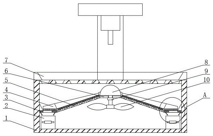
图1为本实用新型整体结构的剖视图;1 is a cross-sectional view of the overall structure of the utility model;
图2为本实用新型整体结构示意图;Fig. 2 is the overall structure schematic diagram of the present utility model;
图3为本实用新型工作台的俯视图;Fig. 3 is the top view of the utility model workbench;
图4为本实用新型图1中A处放大结构图。FIG. 4 is an enlarged structural view of the position A in FIG. 1 of the present utility model.
图中:1-工作台;2-收集盒;3-固定板;4-清洁刷;5-过滤网;6-安装板;7-档条;8-安装块;9-双轴电机;10-风扇;11-箱门;12-通孔;13-挡板;14-防堆环。In the picture: 1- workbench; 2- collection box; 3- fixed plate; 4- cleaning brush; 5- filter screen; 6- installation plate; 7- gear bar; 8- installation block; -Fan; 11-Box door; 12-Through hole; 13-Baffle plate; 14-Anti-stack ring.
具体实施方式Detailed ways
下面将结合本实用新型实施例中的附图,对本实用新型实施例中的技术方案进行清楚、完整地描述,显然,所描述的实施例仅仅是本实用新型一部分实施例,而不是全部的实施例。基于本实用新型中的实施例,本领域普通技术人员在没有做出创造性劳动前提下所获得的所有其他实施例,都属于本实用新型保护的范围。The technical solutions in the embodiments of the present utility model will be clearly and completely described below with reference to the accompanying drawings in the embodiments of the present utility model. Obviously, the described embodiments are only a part of the embodiments of the present utility model, rather than all the implementations. example. Based on the embodiments of the present invention, all other embodiments obtained by those of ordinary skill in the art without creative work fall within the protection scope of the present invention.
请参阅图1-4,本实用新型提供一种技术方案:包括工作台1,所述工作台1的内壁周向表面固定焊接有固定板3,所述固定板3远离工作台1的一侧固定焊接有过滤网5,所述过滤网5的顶部之间固定焊接有安装板6,所述安装板6的底部表面居中处固定安装有双轴电机9,所述双轴电机9的底部一端的输出轴固定套接有风扇10,所述双轴电机9的顶部一端的输出轴贯穿安装板6并延伸至安装板6的外部,所述双轴电机9的输出轴延伸至安装板6外部的一端固定套接有安装块8,所述安装块8的两侧均固定焊接有清洁刷4,所述固定板3的两侧均开设有通孔12,所述工作台1的内壁底部两侧并位于通孔12的底部均滑动连接有收集盒2。Please refer to FIGS. 1-4 , the present utility model provides a technical solution: comprising a
其中,所述工作台1采用具有容纳空腔的圆柱形的结构,并且所述工作台1的顶部表面并位于边缘处固定焊接有档条7,避免碎屑从工作台1掉落带地面,污染了地面的环境。Wherein, the
其中,所述固定板3的底部并位于通孔12的两侧均固定焊接有挡板13,并且所述挡板13与固定板3底部之间的夹角为60度,使得碎屑掉落到收集盒2中。Wherein,
其中,所述工作台1的表面铰链连接有箱门11,并且所述箱门11的表面一侧开设有凹陷部,便于工作台1内部的维修和检修,同时便于将收集盒2内部的碎屑进行处理。The surface of the
其中,所述固定板3的顶部边缘处并位于工作台1的内壁固定焊接有防堆环14,并且所述防堆环14的截面呈三角形的结构,避免碎屑堆积在固定3板的表面不易清理。Wherein, an
其中,所述安装块8采用半球形的结构,并且所述清洁刷4和通孔12均设置有两个,所述清洁刷4和通孔12均关于安装块8中心对称分布,当碎屑掉落到安装块8的表面,可以滑落,避免在安装块8的顶部堆积。The
工作原理:使用时,启动双轴电机9,使得双轴电机9的带动风扇10转动,产生气流引力,使得工作台1表面的碎屑通过下料孔进入工作台1的内部,掉落到固定板3和过滤网5的表面,避免工作台表面堆积影响机床的正常工作,同时双轴电机9带动安装块8转动,使得安装块8带动清洁刷4转动,使得清洁刷4在过滤网5的表面转动,将吸附在过滤网5的表面的碎屑进行清扫,在通过清洁刷4的转动,将碎屑推入到通孔12中掉落到收集盒2的内部进行收集,便于工作人员处理碎屑,当结束后,可以打开箱门11,将收集盒2内部的碎屑倒入垃圾桶内,同时将清洁刷4表面粘附的碎屑进行拾取,然后关闭箱门11,不需要操作人员频繁的去清理碎屑。Working principle: When in use, start the dual-axis motor 9, so that the dual-axis motor 9 drives the fan 10 to rotate, generating airflow attraction, so that the debris on the surface of the
需要说明的是,在本文中,诸如第一和第二等之类的关系术语仅仅用来将一个实体或者操作与另一个实体或操作区分开来,而不一定要求或者暗示这些实体或操作之间存在任何这种实际的关系或者顺序。而且,术语“包括”、“包含”或者其任何其他变体意在涵盖非排他性的包含,从而使得包括一系列要素的过程、方法、物品或者设备不仅包括那些要素,而且还包括没有明确列出的其他要素,或者是还包括为这种过程、方法、物品或者设备所固有的要素。It should be noted that, in this document, relational terms such as first and second are only used to distinguish one entity or operation from another entity or operation, and do not necessarily require or imply any relationship between these entities or operations. any such actual relationship or sequence exists. Moreover, the terms "comprising", "comprising" or any other variation thereof are intended to encompass a non-exclusive inclusion such that a process, method, article or device that includes a list of elements includes not only those elements, but also includes not explicitly listed or other elements inherent to such a process, method, article or apparatus.
尽管已经示出和描述了本实用新型的实施例,对于本领域的普通技术人员而言,可以理解在不脱离本实用新型的原理和精神的情况下可以对这些实施例进行多种变化、修改、替换和变型,本实用新型的范围由所附权利要求及其等同物限定。Although the embodiments of the present invention have been shown and described, it will be understood by those skilled in the art that various changes and modifications can be made to these embodiments without departing from the principles and spirit of the present invention , alternatives and modifications, the scope of the present invention is defined by the appended claims and their equivalents.
Claims (6)
Priority Applications (1)
| Application Number | Priority Date | Filing Date | Title |
|---|---|---|---|
| CN201922199432.0U CN211217841U (en) | 2019-12-10 | 2019-12-10 | A punching machine that can automatically remove debris |
Applications Claiming Priority (1)
| Application Number | Priority Date | Filing Date | Title |
|---|---|---|---|
| CN201922199432.0U CN211217841U (en) | 2019-12-10 | 2019-12-10 | A punching machine that can automatically remove debris |
Publications (1)
| Publication Number | Publication Date |
|---|---|
| CN211217841U true CN211217841U (en) | 2020-08-11 |
Family
ID=71927863
Family Applications (1)
| Application Number | Title | Priority Date | Filing Date |
|---|---|---|---|
| CN201922199432.0U Expired - Fee Related CN211217841U (en) | 2019-12-10 | 2019-12-10 | A punching machine that can automatically remove debris |
Country Status (1)
| Country | Link |
|---|---|
| CN (1) | CN211217841U (en) |
Cited By (1)
| Publication number | Priority date | Publication date | Assignee | Title |
|---|---|---|---|---|
| CN118989711A (en) * | 2024-10-22 | 2024-11-22 | 烟台盛新模具有限公司 | Automatic welding production equipment for automobile floor |
-
2019
- 2019-12-10 CN CN201922199432.0U patent/CN211217841U/en not_active Expired - Fee Related
Cited By (2)
| Publication number | Priority date | Publication date | Assignee | Title |
|---|---|---|---|---|
| CN118989711A (en) * | 2024-10-22 | 2024-11-22 | 烟台盛新模具有限公司 | Automatic welding production equipment for automobile floor |
| CN118989711B (en) * | 2024-10-22 | 2024-12-20 | 烟台盛新模具有限公司 | Automatic welding production equipment for automobile floor |
Similar Documents
| Publication | Publication Date | Title |
|---|---|---|
| CN209363236U (en) | A kind of plate blanking machine dust suction nose shell | |
| CN117066388A (en) | A stamping processing system | |
| CN211217841U (en) | A punching machine that can automatically remove debris | |
| CN211219853U (en) | Copper scrap cleaning and collecting device | |
| CN214441133U (en) | A board cleaning device | |
| CN106217115B (en) | A kind of good Digit Control Machine Tool of chip removal effect | |
| CN217648026U (en) | CNC machining center convenient to collect sweeps | |
| CN213826204U (en) | Electric automatization dust collector | |
| CN115415830A (en) | Numerical control metal cutting machine tool based on cutting fluid recycle | |
| CN212703557U (en) | A pre-cleaning device for glass quality inspection | |
| CN211277040U (en) | UV laser-beam drilling machine with piece recovery unit | |
| CN115158978A (en) | Transfer device for household paper production workshop | |
| CN108481078B (en) | A kind of safe chip removal device of numerical control device | |
| CN220051747U (en) | Machining table for machining mechanical parts | |
| CN216271431U (en) | Feeding device for electronic component production | |
| CN221716347U (en) | An engraving machine with a waste chip cleaning structure | |
| CN221112387U (en) | Prevent piece collection device that splashes | |
| CN219945412U (en) | Drilling device for processing electronic components | |
| CN221968349U (en) | A chip collection device for processing wooden boxes | |
| CN218593209U (en) | Panel processing drilling equipment | |
| CN221675282U (en) | Waste collection device for hardware product processing | |
| CN221755771U (en) | Dust removal device for sanding machine | |
| CN221850720U (en) | Glass drilling equipment | |
| CN218486652U (en) | Electronic component processing device with surface powder cleaning function | |
| CN223013324U (en) | Punching equipment for paper product manufacturing |
Legal Events
| Date | Code | Title | Description |
|---|---|---|---|
| GR01 | Patent grant | ||
| GR01 | Patent grant | ||
| TR01 | Transfer of patent right | ||
| TR01 | Transfer of patent right |
Effective date of registration: 20240326 Address after: 048012, 300 meters east of Langjing Village, Nancun Town, Zezhou County, Jincheng City, Shanxi Province (Nancun New Industrial Park) Patentee after: Jincheng Ruixi Machinery Manufacturing Co.,Ltd. Country or region after: China Address before: No.76, Fenghuang East Road, Hailing District, Taizhou City, Jiangsu Province 225300 Patentee before: Taizhou Yuxin Microelectronics Co.,Ltd. Country or region before: China |
|
| CF01 | Termination of patent right due to non-payment of annual fee | ||
| CF01 | Termination of patent right due to non-payment of annual fee |
Granted publication date: 20200811 |