CN211198537U - Device for opening electric working well cover plate - Google Patents
Device for opening electric working well cover plate Download PDFInfo
- Publication number
- CN211198537U CN211198537U CN201921464976.9U CN201921464976U CN211198537U CN 211198537 U CN211198537 U CN 211198537U CN 201921464976 U CN201921464976 U CN 201921464976U CN 211198537 U CN211198537 U CN 211198537U
- Authority
- CN
- China
- Prior art keywords
- bearing beam
- plate
- cover plate
- opening
- working well
- Prior art date
- Legal status (The legal status is an assumption and is not a legal conclusion. Google has not performed a legal analysis and makes no representation as to the accuracy of the status listed.)
- Active
Links
Images


Landscapes
- Types And Forms Of Lifts (AREA)
Abstract
The utility model discloses a device for opening electric power working well cover plate, which comprises a bearing beam, two longitudinal rods arranged on the bearing beam, a chain arranged on each longitudinal rod, at least one hook arranged at the lower end of the chain, two plate trolleys, jacks arranged on each plate trolley, and a bracket arranged on each jack; two brackets are respectively contacted with the left part and the right part of the bearing beam, and two longitudinal rods are both connected with the bearing beam in a sliding manner. The utility model has the characteristics of convenient operation, security are good.
Description
Technical Field
The utility model belongs to the technical field of electric power work well equipment technique and specifically relates to a device for opening electric power work well cover board that convenient operation, security are good is related to.
Background
Due to the needs of city matching planning and matching facility construction, overhead lines on two sides of an urban road are transformed into the ground, meanwhile, in order to supply power more reliably, the influence of weather (such as typhoon, thunderstorm, freezing, snowstorm and the like) is reduced to the minimum, and electric wires are also continuously inserted into the ground. So the number of ducts for cables is increasing.
And due to the requirement of city lifting, a plurality of sidewalks are lifted, the granite cover plates of the working well are more and more, the weight of each cover plate is increased, and the weight of one cover plate reaches 300 kilograms.
Therefore, the operation of opening and resetting the cover plates becomes frequent work in power construction, 4 persons are usually needed to lift the first cover plate, and the rest cover plates need to be turned out and are sequentially turned back when being reset. If the cover plate is damaged or falls into the inspection well in the opening process of the cover plate, equipment is easily damaged, and the problem that hands and feet are easily scratched in the opening and resetting processes is easily caused.
Disclosure of Invention
The utility model aims at overcoming the operation intensity of labour who opens, resets apron among the prior art and being big, easily cause equipment damage, easily take place to wipe the not enough of broken hand, foot, provide a convenient operation, the good device that is used for opening electric power work well apron of security.
In order to achieve the above purpose, the utility model adopts the following technical scheme:
a device for opening a cover plate of an electric working well comprises a bearing beam, two longitudinal rods arranged on the bearing beam, a chain arranged on each longitudinal rod, at least one lifting hook arranged at the lower end of the chain, two plate trolleys, jacks arranged on each plate trolley and a bracket arranged on each jack; two brackets are respectively contacted with the left part and the right part of the bearing beam, and two longitudinal rods are both connected with the bearing beam in a sliding manner.
The bearing beam is used for supporting the weight of the electric working well cover plate, and the two longitudinal rods are used for driving the lifting hook to move left and right relative to the bearing beam, so that the position of the lifting hook is correspondingly connected with a hanging buckle reserved on the electric working well cover plate; the two jacks are used for lifting the left part and the right part of the bearing beam so as to drive the lifting hook to lift and complete the operation of opening and resetting the cover plate; the two plate trolleys are used for driving the two jacks and the load beam to move respectively, so that the labor intensity is effectively reduced, the hands of an operator do not need to be in direct contact with the cover plate, and the operation safety is improved.
Preferably, the bearing beam comprises a rectangular frame, and 3 reinforcing rods are arranged on the rectangular frame; 3 reinforcing rods are arranged at intervals along the length direction of the bearing beam.
The rectangular frame and the 3 reinforcing rods are arranged, so that the strength, stability and reliability of the bearing beam are improved.
Preferably, the rectangular frame comprises two vertical rods and two transverse rods, the length of each vertical rod is larger than that of each transverse rod, sliding grooves are formed in the upper surfaces of the two vertical rods, and the two ends of each vertical rod are connected with the two sliding grooves through sliding blocks respectively.
The setting of spout and slider, the longitudinal bar of being convenient for along spandrel girder continuous movement, make the utility model discloses a lifting hook can be with the suspension clasp accordant connection of the apron of different specifications.
Preferably, the plate trailer comprises a rectangular plate, a U-shaped limit frame arranged on the rectangular plate, handrails arranged on one side of the rectangular plate and rollers arranged at 4 corners of the lower surface of the rectangular plate.
The U-shaped limiting frame is fixedly connected with the lower part of the jack through a plurality of bolts; the arrangement of the handrail enables an operator to grasp the handrail and push the scooter to move, thereby being more labor-saving and improving the personal safety of the operator.
Preferably, the handrail is triangular.
Preferably, the bracket is in a U shape with an upward opening, and two sides of the bracket are respectively contacted with the front side surface of one vertical rod and the rear side surface of the other vertical rod.
The bracket of U-shaped contacts with spandrel girder lower part, front side and rear side, and the spandrel girder is restricted on 2 brackets, is difficult to remove, has improved stability and security when the operation.
Preferably, the bearing beam is made of high-strength aluminum alloy materials, and each jack is a vertical jack.
Therefore, the utility model discloses following beneficial effect has: the labor intensity is effectively reduced, the operation is convenient, the stability and the reliability are high, and the safety is good.
Drawings
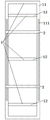
Fig. 1 is a side view of the present invention;
FIG. 2 is a top view of the rectangular frame of the present invention;
FIG. 3 is a schematic view of the longitudinal bar, chain and hook of the present invention;
FIG. 4 is a top view of the pallet truck of the present invention;
fig. 5 is a side view of the jack and bracket of the present invention.
In the figure: spandrel girder 1, vertical pole 2, chain 3, lifting hook 4, wooden handcart 5, jack 6, bracket 7, rectangle frame 11, stiffener 12, slider 21, rectangular plate 51, U-shaped spacing frame 52, handrail 53, gyro wheel 54, spout 111.
Detailed Description
The invention is further described with reference to the accompanying drawings and the detailed description.
The embodiment shown in fig. 1, 2, 3 and 5 is a device for opening a cover plate of an electric working well, which comprises a bearing beam 1, two longitudinal rods 2 arranged on the bearing beam, a chain 3 arranged on each longitudinal rod, 2 lifting hooks 4 arranged at the lower end of each chain, two plate trolleys 5, a jack 6 arranged on each plate trolley, and a bracket 7 arranged on each jack; two brackets are respectively contacted with the left part and the right part of the bearing beam, and two longitudinal rods are both connected with the bearing beam in a sliding manner.
The bearing beam comprises a rectangular frame 11 and 3 reinforcing rods 12 arranged on the rectangular frame; 3 reinforcing rods are arranged at intervals along the length direction of the bearing beam.
The rectangular frame comprises two vertical rods and two transverse rods, the length of each vertical rod is larger than that of each transverse rod, sliding grooves 111 are formed in the upper surfaces of the two vertical rods, and the two ends of each vertical rod are connected with the two sliding grooves through sliding blocks 21 respectively.
As shown in fig. 4, the pallet truck includes a rectangular plate 51, a U-shaped stopper frame 52 provided on the rectangular plate, a handrail 53 provided on one side of the rectangular plate, and rollers 54 provided at 4 corners of the lower surface of the rectangular plate.
The handrail is triangular. The bracket is in a U shape with an upward opening, and two sides of the bracket are respectively contacted with the front side surface of one vertical rod and the rear side surface of the other vertical rod. The spandrel girder is made of high-strength aluminum alloy materials, and each jack is a vertical jack.
The utility model discloses a use method as follows:
placing the two vertical jacks on the two lathes respectively, fixedly connecting the U-shaped limiting frame with the bottoms of the vertical jacks to enable the two brackets to be aligned with the left part and the right part of the bearing beam respectively, and placing the bearing beam on the two brackets;
opening the cover plate: two operators respectively push the two handrails to move the bearing beam to the position above the electric power working well cover plate to be opened, and the lifting hooks are correspondingly connected with the lifting buckles reserved on the electric power working well cover plate;
the two vertical jacks drive the bearing beam to ascend, the electric working well cover plate leaves the electric working well, and the two operators respectively push the two handrails to move away the electric working well cover plate;
resetting the cover plate: two operators respectively push the two handrails to enable the bearing beam to drive the electric power working well cover plate to move to the position above the electric power working well, the two vertical jacks drive the bearing beam to descend, the electric power working well cover plate is placed on the electric power working well again, each lifting hook is separated from a hanging buckle reserved on the electric power working well cover plate, and the two operators respectively push the two handrails to move the bearing beam away.
It should be understood that the present embodiment is only for illustrating the present invention and is not intended to limit the scope of the present invention. Furthermore, it should be understood that various changes and modifications of the present invention may be made by those skilled in the art after reading the teachings of the present invention, and these equivalents also fall within the scope of the appended claims.
Claims (7)
1. A device for opening a cover plate of an electric working well is characterized by comprising a bearing beam (1), two longitudinal rods (2) arranged on the bearing beam, a chain (3) arranged on each longitudinal rod, at least one lifting hook (4) arranged at the lower end of the chain, two plate trolleys (5), a jack (6) arranged on each plate trolley, and a bracket (7) arranged on each jack; two brackets are respectively contacted with the left part and the right part of the bearing beam, and two longitudinal rods are both connected with the bearing beam in a sliding manner.
2. A device for opening an electric working well cover plate according to claim 1, characterized in that the load beam comprises a rectangular frame (11) with 3 reinforcing bars (12) arranged thereon; 3 reinforcing rods are arranged at intervals along the length direction of the bearing beam.
3. Device for opening the lids of electric working wells, according to claim 2, characterised in that the rectangular frame comprises two vertical bars and two transverse bars, the length of the vertical bars being greater than the length of the transverse bars, the two vertical bars being provided with sliding grooves (111) on their upper surfaces, the two ends of the vertical bars being connected to the two sliding grooves respectively by means of sliding blocks (21).
4. The apparatus for opening an electric work well cover plate according to claim 1, wherein the plate trailer comprises a rectangular plate (51), a U-shaped stop frame (52) provided on the rectangular plate, a handle (53) provided on one side of the rectangular plate, and rollers (54) provided on 4 corners of a lower surface of the rectangular plate.
5. An apparatus for opening an electric working well lid plate according to claim 4, wherein the armrest is triangular in shape.
6. The apparatus as claimed in claim 2, wherein the bracket has a U shape opened upward, and both sides of the bracket are in contact with a front side of one vertical rod and a rear side of the other vertical rod, respectively.
7. An apparatus for opening a cover plate of an electric working well according to claim 1 or 2 or 3 or 4 or 5 or 6, wherein the load beam is made of high strength aluminum alloy material, and each jack is a vertical jack.
Priority Applications (1)
| Application Number | Priority Date | Filing Date | Title |
|---|---|---|---|
| CN201921464976.9U CN211198537U (en) | 2019-09-04 | 2019-09-04 | Device for opening electric working well cover plate |
Applications Claiming Priority (1)
| Application Number | Priority Date | Filing Date | Title |
|---|---|---|---|
| CN201921464976.9U CN211198537U (en) | 2019-09-04 | 2019-09-04 | Device for opening electric working well cover plate |
Publications (1)
| Publication Number | Publication Date |
|---|---|
| CN211198537U true CN211198537U (en) | 2020-08-07 |
Family
ID=71882771
Family Applications (1)
| Application Number | Title | Priority Date | Filing Date |
|---|---|---|---|
| CN201921464976.9U Active CN211198537U (en) | 2019-09-04 | 2019-09-04 | Device for opening electric working well cover plate |
Country Status (1)
| Country | Link |
|---|---|
| CN (1) | CN211198537U (en) |
Cited By (1)
| Publication number | Priority date | Publication date | Assignee | Title |
|---|---|---|---|---|
| CN112591691A (en) * | 2020-11-27 | 2021-04-02 | 国网浙江省电力有限公司金华供电公司 | Lifting device for lifting cable well cover plate |
-
2019
- 2019-09-04 CN CN201921464976.9U patent/CN211198537U/en active Active
Cited By (1)
| Publication number | Priority date | Publication date | Assignee | Title |
|---|---|---|---|---|
| CN112591691A (en) * | 2020-11-27 | 2021-04-02 | 国网浙江省电力有限公司金华供电公司 | Lifting device for lifting cable well cover plate |
Similar Documents
| Publication | Publication Date | Title |
|---|---|---|
| CN211198537U (en) | Device for opening electric working well cover plate | |
| CN205838045U (en) | A kind of hydraulic lifting tipper | |
| CN203247031U (en) | Hoisting device for curtain board transporting | |
| CN206766053U (en) | Underneath type mechanical arm electric pole transport vehicle | |
| CN207017153U (en) | Main push-towing rope inspection trolley lifting device | |
| CN206800228U (en) | Remove the frame mounting of arch bridge | |
| CN210710461U (en) | Lifting device for processing quartz stone slabs | |
| CN107720609A (en) | A kind of multi-functional forest conveying arrangement | |
| CN211665589U (en) | Post-tensioning simply supported box girder prestress tensioning trolley | |
| CN214935462U (en) | Bridge crane capable of lifting in sectional mode | |
| CN202541599U (en) | Lifting handcart | |
| CN205524327U (en) | Novel fortune pole gun carriage | |
| CN210825161U (en) | Sand box and box turnover device thereof | |
| CN210176324U (en) | Trolley hoisting device | |
| CN207330239U (en) | A kind of forest processing transporting equipment | |
| CN111532315A (en) | Switch cabinet transferring method | |
| CN215924312U (en) | Material lifting device of tunnel equipment installation trolley | |
| CN205011292U (en) | Movable thermal treatment sample sling cart | |
| CN206128656U (en) | A instrument for transporting installation roof boarding | |
| CN204824005U (en) | Novel cut fork lifter | |
| CN218141574U (en) | Nitrogen cylinder floor truck | |
| CN210595016U (en) | Jack hoist and mount operation platform | |
| CN219314341U (en) | Novel hoisting mechanism | |
| CN212687364U (en) | I-steel stone tongs and novel electronic monospar driving | |
| CN214823353U (en) | Hand buggy for beehive transition |
Legal Events
| Date | Code | Title | Description |
|---|---|---|---|
| GR01 | Patent grant | ||
| GR01 | Patent grant |