CN211190394U - Double-shaft crusher for organic fertilizer production - Google Patents
Double-shaft crusher for organic fertilizer production Download PDFInfo
- Publication number
- CN211190394U CN211190394U CN201922080979.9U CN201922080979U CN211190394U CN 211190394 U CN211190394 U CN 211190394U CN 201922080979 U CN201922080979 U CN 201922080979U CN 211190394 U CN211190394 U CN 211190394U
- Authority
- CN
- China
- Prior art keywords
- crushing
- rotating shaft
- crushing cavity
- cavity
- cutter
- Prior art date
- Legal status (The legal status is an assumption and is not a legal conclusion. Google has not performed a legal analysis and makes no representation as to the accuracy of the status listed.)
- Active
Links
Images


Abstract
The utility model discloses a double-shaft crusher for producing organic fertilizer, which comprises a frame, a crushing cavity and a power mechanism, wherein the crushing cavity and the power mechanism are arranged on the frame, a feed inlet is arranged above the crushing cavity, a discharge outlet is arranged below the crushing cavity, two crushing mechanisms are arranged in the crushing cavity, each crushing mechanism comprises a rotating shaft and a plurality of crushing cutter discs fixedly sleeved on the rotating shaft, and a plurality of hammer sheets are arranged on each crushing cutter disc; the two rotating shafts are horizontally arranged and are arranged up and down, and the two rotating shafts are parallel to each other, so that the two crushing mechanisms correspond to the crushing area to form a first crushing cavity and a second crushing cavity in the crushing cavity, the rotating shaft positioned in the first crushing cavity is the first rotating shaft, the rotating shaft positioned in the second crushing cavity is the second rotating shaft, the feeding port is arranged in the first crushing cavity, and the discharging port is arranged in the second crushing cavity; the power mechanism is composed of two motors with different powers, the motor with smaller relative power is connected with the first rotating shaft, and the motor with larger relative power is connected with the second rotating shaft. The crusher effectively avoids material blockage and improves crushing efficiency.
Description
Technical Field
The utility model relates to a fertilizer production technical field, concretely relates to double-shaft crusher is used in fertilizer production.
Background
The organic fertilizer is a fertilizer which is compounded by microorganisms with specific functions and organic materials mainly prepared from animal and plant residues (such as livestock and poultry manure, crop straws, garden garbage and the like) through harmless treatment and decomposition.
In the production process of the organic fertilizer, the composted materials such as crop straws, garden garbage and the like need to be crushed firstly, and at present, a crusher shown in figures 1 and 2 is adopted for crushing, wherein the crusher comprises a rack and a crushing cavity on the rack 1, a feed inlet is arranged above the crushing cavity, a discharge outlet 6 is arranged below the crushing cavity, and a feed hopper 9 is arranged at the feed inlet; a crushing mechanism is arranged in the crushing cavity, the crushing mechanism comprises a rotating shaft 4 and a plurality of crushing cutter discs 2 fixedly sleeved on the rotating shaft 4, all the crushing cutter discs 2 are arranged at intervals and are connected through a plurality of cutter shafts uniformly arranged along the circumference of each crushing cutter disc, a plurality of hammer sheets 3 are arranged on the cutter shafts between two adjacent crushing cutter discs at intervals, and the rotating shaft 4 is connected with a main motor 5 so as to drive the hammer sheets of all the crushing cutter discs on the rotating shaft to rotate to crush materials in the crushing cavity; a discharging auger 7 is arranged in the crushing cavity corresponding to the discharging port 6, and the discharging auger 7 is controlled by a discharging auger motor speed reducing motor 8; and meanwhile, a screen is arranged below the discharge port 6, so that the crushed materials can be conveniently screened. However, the composted materials have large particle size (about 10 cm) and high water content (over 45%), the materials are crushed by the crusher, the materials are easy to block a screen of the crusher or are clamped in the crusher, the crusher stops working, the blocked screen and the materials in the crusher need to be cleaned manually, the crushing efficiency is influenced, and the crusher can only crush 2 t of materials per hour.
Therefore, how to solve the material blockage and improve the crushing efficiency is a technical problem to be solved urgently by technical personnel in the field.
Disclosure of Invention
Not enough to the above-mentioned that prior art exists, the utility model aims at providing a fertilizer production is with two axle crusher just, and this breaker has effectively avoided the material to block up the breaker, has improved crushing efficiency.
The technical scheme of the utility model is realized like this:
a double-shaft crusher for producing organic fertilizers comprises a rack, a crushing cavity and a power mechanism, wherein the crushing cavity and the power mechanism are arranged on the rack, a feed inlet is formed above the crushing cavity, a discharge outlet is formed below the crushing cavity, a crushing mechanism is arranged in the crushing cavity and comprises a rotating shaft and a plurality of crushing cutter discs fixedly sleeved on the rotating shaft, all the crushing cutter discs are arranged at intervals and connected through a plurality of cutter shafts uniformly arranged along the circumference of each crushing cutter disc, and a plurality of hammer sheets are arranged on the cutter shafts between every two adjacent crushing cutter discs at intervals; the crushing mechanism is by two, and two pivot levels that two crushing mechanisms correspond are placed and are set up from top to bottom to two pivots are parallel to each other, thereby two crushing mechanisms that set up from top to bottom correspond broken district and form first broken chamber and the broken chamber of second in broken intracavity, and the pivot that is located first broken chamber is first pivot, and the pivot that is located the broken chamber of second is the second pivot, first broken chamber is located to the feed inlet, and the broken chamber of second is located to the discharge gate, and first broken chamber and the broken chamber of second communicate with each other and set up, are convenient for the material after the first broken chamber is broken gets into the broken chamber of second.
The power mechanism is two motors with different powers, the motor with smaller relative power is connected with the first rotating shaft to drive the hammer sheets of all the crushing cutter discs on the first rotating shaft to rotate so as to crush the materials entering the first crushing cavity, and the motor with larger relative power is connected with the second rotating shaft to drive the hammer sheets of all the crushing cutter discs on the second rotating shaft to rotate so as to crush the materials entering the second crushing cavity.
Furthermore, the first rotating shaft and the second rotating shaft are separated by a certain distance in the horizontal direction, so that an included angle is formed between the plane where the first rotating shaft and the second rotating shaft are located and the horizontal plane, and the lower surfaces of the plane where the first rotating shaft and the second rotating shaft are located are parallel to the plane where the first rotating shaft and the second rotating shaft are located corresponding to the inner wall of the crushing cavity.
Further, the included angle is 45 °.
Furthermore, through holes are formed in the crushing cutter heads corresponding to the cutter shafts, and the cutter shafts penetrate through the through holes of all the corresponding crushing cutter heads and are fixed on the crushing cutter heads through welding; the hammer sheets are sleeved on the corresponding cutter shafts and can do circular motion with a certain angle on the cutter shafts, and a spacer block is arranged between every two adjacent hammer sheets to separate the two adjacent hammer sheets, and the spacer block is sleeved on the cutter shafts.
Furthermore, through holes which correspond to the first rotating shaft and the second rotating shaft and are equal in size are respectively formed in the wall of the first crushing cavity and the wall of the second crushing cavity, the two ends of the first rotating shaft and the two ends of the second rotating shaft extend out of the corresponding crushing cavities, and supporting frames are respectively arranged on the outer walls of the crushing cavities which correspond to the two ends of the first rotating shaft and the two ends of the second rotating shaft and used for supporting the first rotating shaft and the second rotating shaft.
Furthermore, the feed inlet department is equipped with the feeder hopper, feeder hopper department is equipped with the feeding conveyer belt, is convenient for carry the material.
Furthermore, a discharging conveyor belt is arranged below the discharging port, so that the crushed materials can be conveyed away in time.
Furthermore, driving wheels are arranged on output shafts of the two motors, driven wheels are arranged on corresponding rotating shafts, and the driving wheels and the corresponding driven wheels are connected through belts.
Compared with the prior art, the utility model discloses following beneficial effect has:
1. the utility model discloses a second grade is broken, adopts the motor that power is less relatively earlier to drive crushing mechanism and carries out the one-level breakage to the material, then adopts the motor that power is great relatively to drive crushing mechanism and carries out the second grade breakage to the material, broken material has been avoided the material card in broken intracavity gradually like this to material after twice breakage satisfies the requirement as fertilizer base fertilizer, thereby need not set up the screen cloth in the breaker bottom, and then avoids the material to block up the screen cloth.
2. First pivot and second pivot place plane are 45 contained angles with the level, have balanced the crushing load in first broken chamber and the broken chamber of second, are favorable to the great material of particle diameter fully broken in first broken chamber, have also alleviated the crushing pressure in the broken chamber of second simultaneously for the material is broken more thinly in the breaker, and two crushing mechanism synergism are favorable to improving crushing efficiency.
3. The utility model discloses a second grade is broken, has avoided the material card in broken intracavity, has avoided the material to block up the screen cloth simultaneously for the breaker can last stable work, has improved crushing efficiency.
Drawings
Fig. 1-schematic view of a prior art crusher.
Fig. 2-a cross-section view of fig. 1.
Fig. 3-the structure of the present invention.
Wherein: 1-a frame; 2-crushing cutter head; 21-a first rotary cutter head; 22-a second rotary cutter head; 3-hammer slice; 31-a first hammer; 32-a second hammer slice; 4-a rotating shaft; 41-a first shaft; 42-a second shaft; 5-a main motor; 51-a first motor; 52-a second motor; 6-discharging port; 7-discharging auger; 8-discharging auger motor reducer; 9-a feed hopper; 10-a first support frame; 11-second support.
Detailed Description
The present invention will be described in further detail with reference to the accompanying drawings and specific embodiments.
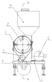
Referring to fig. 3, a double-shaft crusher for producing organic fertilizer comprises a frame 1, a crushing cavity and a power mechanism, wherein the crushing cavity and the power mechanism are arranged on the frame 1, a feed inlet is arranged above the crushing cavity 1, a discharge outlet (not shown) is arranged below the crushing cavity, a crushing mechanism is arranged in the crushing cavity, the crushing mechanism comprises a rotating shaft and a plurality of crushing cutter discs 2 fixedly sleeved on the rotating shaft, all the crushing cutter discs 2 are arranged at intervals and connected through a plurality of cutter shafts uniformly arranged along the circumference of each crushing cutter disc 2, and a plurality of hammer sheets 3 are arranged on the cutter shafts between two adjacent crushing cutter discs at intervals; the crushing mechanism is by two, and two pivot levels that two crushing mechanisms correspond are placed and are set up from top to bottom to two pivots are parallel to each other, thereby two crushing mechanisms that set up from top to bottom correspond broken district and form first broken chamber and the broken chamber of second in broken intracavity, and the pivot that is located first broken chamber is first pivot 41, and the pivot that is located the broken chamber of second is second pivot 42, first broken chamber is located to the feed inlet, and the broken chamber of second is located to the discharge gate, and first broken chamber and the broken chamber of second communicate with each other and set up, are convenient for the material after the first broken chamber is broken gets into the broken chamber of second. Thus, the crushing cutterhead and the hammer blades on the first rotating shaft 41 are referred to as the first crushing cutterhead 21 and the first hammer blade 31, respectively; the breaker discs and the hammer blades on the second rotor shaft 42 are referred to as the second breaker disc 22 and the second hammer blade 32, respectively.
The power mechanism is two motors with different powers, a motor with smaller relative power (called as a first motor 51) is connected with the first rotating shaft to drive the hammer sheets of all the crushing cutter discs on the first rotating shaft to rotate so as to crush the materials entering the first crushing cavity, and a motor with larger relative power (called as a second motor 52) is connected with the second rotating shaft to drive the hammer sheets of all the crushing cutter discs on the second rotating shaft to rotate so as to crush the materials entering the second crushing cavity.
The power of first motor is 37 kw in this embodiment, the power of second motor is 45 kw, the material gets into first broken chamber and carries out preliminary breakage, the material that will be about 10 cm is preliminary broken into the particle diameter and is 3~5 cm, then the material after preliminary breakage under the effect of material gravity and centrifugal force gets into the broken chamber of second, because of having passed through preliminary breakage, the material is good at the broken chamber dispersibility of second, the broken dynamics of motor to the material that adopts power higher is bigger, thereby can be broken into the particle diameter below 2 cm once more with the material that the particle diameter is 3~5 cm.
In specific implementation, the first rotating shaft 41 and the second rotating shaft 42 are spaced apart by a distance in the horizontal direction, so that an included angle is formed between the plane where the first rotating shaft 41 and the second rotating shaft 42 are located and the horizontal plane, and the lower surface of the plane where the first rotating shaft and the second rotating shaft are located is parallel to the plane where the first rotating shaft and the second rotating shaft are located corresponding to the inner wall of the crushing cavity.
Like this, first pivot and the slope of second pivot set up, and the crushing intracavity wall that corresponds simultaneously is the same slopes, can avoid getting into the broken not abundant of material in the first crushing intracavity, just directly gets into the broken chamber of second under the action of gravity.
In specific implementation, the included angle is 45 °.
Therefore, the crushing loads of the first crushing cavity and the second crushing cavity can be balanced, if the included angle is 30 degrees, the inner wall of the crushing cavity supports materials to a certain extent, so that the speed of the materials entering the second crushing cavity is low, the materials conveyed into the first crushing cavity are kept unchanged, and the crushing load of the first crushing cavity is increased; similarly, when the contained angle is 60, the speed that gets into the material in the broken chamber of second is very fast, has just so increaseed the crushing load in the broken chamber of second for the breaker keeps lasting stable work, has improved crushing efficiency, can handle 15~20 t materials per hour.
In specific implementation, through holes are formed in the crushing cutter heads corresponding to the cutter shafts, and the cutter shafts penetrate through the through holes of all the corresponding crushing cutter heads 2 and are fixed on the crushing cutter heads 2 through welding; the hammer slice 3 is sleeved on the corresponding cutter shaft and can do circular motion with a certain angle on the cutter shaft; and a spacer block is arranged between every two adjacent hammer sheets to separate the two adjacent hammer sheets, and the spacer block is sleeved on the cutter shaft.
In the embodiment, the four cutter shafts are arranged, and the hammer blades on the adjacent cutter shafts of the same crushing mechanism are arranged in a staggered manner, so that a gap can be formed to crush the material, and the material can be fully crushed; meanwhile, the number of the hammer sheets on each cutter shaft on the same crushing mechanism is consistent, so that the power balance of the crushing mechanism is favorably ensured.
During specific implementation, through holes which correspond to the first rotating shaft 41 and the second rotating shaft 42 and are equal in size are respectively formed in the wall of each of the first crushing cavity and the second crushing cavity, two ends of the first rotating shaft 41 and two ends of the second rotating shaft 42 extend out of the corresponding crushing cavities, and supporting frames are respectively arranged on the outer walls of the crushing cavities corresponding to two ends of the first rotating shaft 3 and two ends of the second rotating shaft 4, wherein the first supporting frame 10 is used for supporting the first rotating shaft 41, and the second supporting frame 11 is used for supporting the second rotating shaft 42.
During specific implementation, feed inlet department is equipped with feeder hopper 9, feeder hopper 9 department is equipped with the feeding conveyer belt, is convenient for carry the material.
When the material conveying device is specifically implemented, a discharging conveyor belt is arranged below the discharging port, so that the crushed materials can be conveyed away in time.
When the device is specifically implemented, the output shafts of the two motors are respectively provided with a driving wheel, the corresponding rotating shafts are provided with driven wheels, and the driving wheels and the corresponding driven wheels are connected through belts.
Finally, it should be noted that the above-mentioned embodiments of the present invention are only examples for illustrating the present invention, and are not limitations to the embodiments of the present invention. Variations and modifications in other variations will occur to those skilled in the art upon reading the foregoing description. Not all embodiments are exhaustive. All obvious changes or variations which are introduced by the technical solution of the present invention are still within the scope of the present invention.
Claims (8)
1. A double-shaft crusher for producing organic fertilizers comprises a rack, a crushing cavity and a power mechanism, wherein the crushing cavity and the power mechanism are arranged on the rack, a feed inlet is formed above the crushing cavity, a discharge outlet is formed below the crushing cavity, a crushing mechanism is arranged in the crushing cavity and comprises a rotating shaft and a plurality of crushing cutter discs fixedly sleeved on the rotating shaft, all the crushing cutter discs are arranged at intervals and connected through a plurality of cutter shafts uniformly arranged along the circumference of each crushing cutter disc, and a plurality of hammer sheets are arranged on the cutter shafts between every two adjacent crushing cutter discs at intervals; the crushing mechanism is characterized by comprising two crushing mechanisms, wherein two rotating shafts corresponding to the two crushing mechanisms are horizontally arranged and vertically arranged and are parallel to each other, so that the two crushing mechanisms vertically arranged correspond to a crushing area to form a first crushing cavity and a second crushing cavity in the crushing cavity, the rotating shaft in the first crushing cavity is the first rotating shaft, the rotating shaft in the second crushing cavity is the second rotating shaft, the feeding hole is formed in the first crushing cavity, the discharging hole is formed in the second crushing cavity, and the first crushing cavity and the second crushing cavity are communicated with each other so that materials crushed in the first crushing cavity can conveniently enter the second crushing cavity;
the power mechanism is two motors with different powers, the motor with smaller relative power is connected with the first rotating shaft to drive the hammer sheets of all the crushing cutter discs on the first rotating shaft to rotate so as to crush the materials entering the first crushing cavity, and the motor with larger relative power is connected with the second rotating shaft to drive the hammer sheets of all the crushing cutter discs on the second rotating shaft to rotate so as to crush the materials entering the second crushing cavity.
2. The twin-shaft crusher for producing organic fertilizer as claimed in claim 1, wherein the first rotating shaft and the second rotating shaft are spaced apart from each other at a distance in the horizontal direction, so that the plane of the first rotating shaft and the plane of the second rotating shaft form an included angle with the horizontal plane, and the lower surface of the plane of the first rotating shaft and the second rotating shaft is parallel to the plane of the first rotating shaft and the second rotating shaft corresponding to the inner wall of the crushing chamber.
3. The twin-shaft crusher for producing organic fertilizer as claimed in claim 2, wherein the included angle is 45 °.
4. The double-shaft crusher for producing the organic fertilizer as claimed in claim 1, wherein through holes are formed in the positions of the crushing cutter discs corresponding to the cutter shafts, and the cutter shafts penetrate through the through holes of all the corresponding crushing cutter discs and are fixed on the crushing cutter discs through welding; the hammer sheets are sleeved on the corresponding cutter shafts and can do circular motion with a certain angle on the cutter shafts, and a spacer block is arranged between every two adjacent hammer sheets to separate the two adjacent hammer sheets, and the spacer block is sleeved on the cutter shafts.
5. The double-shaft crusher for producing organic fertilizer as claimed in claim 1, wherein through holes with the same size as the first rotating shaft and the second rotating shaft are respectively arranged on the wall of the first crushing cavity and the wall of the second crushing cavity, two ends of the first rotating shaft and two ends of the second rotating shaft extend out of the corresponding crushing cavities, and supporting frames are respectively arranged on the outer walls of the crushing cavities corresponding to the two ends of the first rotating shaft and the second rotating shaft and used for supporting the first rotating shaft and the second rotating shaft.
6. The double-shaft crusher for producing organic fertilizers as claimed in claim 1, wherein a feed hopper is arranged at the feed inlet, and a feed conveyor belt is arranged at the feed hopper for conveying materials conveniently.
7. The double-shaft crusher for producing organic fertilizers according to claim 1, wherein a discharge conveyor belt is arranged below the discharge port, so that crushed materials can be conveyed away in time.
8. The double-shaft crusher for producing organic fertilizers as claimed in claim 1, wherein the output shafts of the two motors are respectively provided with a driving wheel, the corresponding rotating shafts are provided with a driven wheel, and the driving wheels and the corresponding driven wheels are connected through belts.
Priority Applications (1)
| Application Number | Priority Date | Filing Date | Title |
|---|---|---|---|
| CN201922080979.9U CN211190394U (en) | 2019-11-27 | 2019-11-27 | Double-shaft crusher for organic fertilizer production |
Applications Claiming Priority (1)
| Application Number | Priority Date | Filing Date | Title |
|---|---|---|---|
| CN201922080979.9U CN211190394U (en) | 2019-11-27 | 2019-11-27 | Double-shaft crusher for organic fertilizer production |
Publications (1)
| Publication Number | Publication Date |
|---|---|
| CN211190394U true CN211190394U (en) | 2020-08-07 |
Family
ID=71887813
Family Applications (1)
| Application Number | Title | Priority Date | Filing Date |
|---|---|---|---|
| CN201922080979.9U Active CN211190394U (en) | 2019-11-27 | 2019-11-27 | Double-shaft crusher for organic fertilizer production |
Country Status (1)
| Country | Link |
|---|---|
| CN (1) | CN211190394U (en) |
-
2019
- 2019-11-27 CN CN201922080979.9U patent/CN211190394U/en active Active
Similar Documents
| Publication | Publication Date | Title |
|---|---|---|
| CN206182320U (en) | Fodder granule apparatus for producing | |
| CN208050118U (en) | A kind of feed production technology rapidly and efficiently grinding device | |
| CN207287663U (en) | A kind of high-efficient feed grinder | |
| CN110934000A (en) | Crop straw pulverizer | |
| CN214178153U (en) | Rice straw crushing and returning equipment | |
| CN212142976U (en) | Rubbing crusher device of usefulness is made to amino acid fertilizer | |
| CN214155444U (en) | Straw cutting and rubbing machine | |
| CN211190394U (en) | Double-shaft crusher for organic fertilizer production | |
| CN215540472U (en) | Edible mushroom culture medium mixing arrangement | |
| CN211936737U (en) | Mixing arrangement is used in organic fertilizer production | |
| CN212936805U (en) | Straw smashing device | |
| CN211359092U (en) | Biax linkage fertilizer raw materials rubbing crusher | |
| CN211329625U (en) | Fertilizer reducing mechanism | |
| CN109845499B (en) | Novel crop pulverizer | |
| CN209772307U (en) | Fertilizer production is with high-efficient reducing mechanism | |
| CN209576906U (en) | A kind of crops crusher improving powder feeding efficiency | |
| CN207786742U (en) | A kind of crops stalk crushing device | |
| CN208771585U (en) | A kind of biological organic fertilizer production upender with crushing function | |
| CN111837670A (en) | Thousand heavy straw rubbing crusher that removes of formula that draws | |
| CN111686892A (en) | A raw materials crushing apparatus for bio-organic fertilizer | |
| CN206549599U (en) | Swine manure material amphitypy granulating system | |
| CN213886483U (en) | Crushing apparatus of fertilizer raw materials | |
| CN206027866U (en) | High -efficiency crusher | |
| CN218013061U (en) | Crusher for crop straws | |
| CN218742189U (en) | Rubbing crusher constructs for amino acid fertilizer production |
Legal Events
| Date | Code | Title | Description |
|---|---|---|---|
| GR01 | Patent grant | ||
| GR01 | Patent grant | ||
| TR01 | Transfer of patent right |
Effective date of registration: 20210525 Address after: 401120 guiwan village, LUOQI Town, Yubei District, Chongqing Patentee after: Chongqing Yuhuan bioenergy Co.,Ltd. Address before: Building 1, No. 174, east section of Huangshan Avenue, Renhe, Yubei District, Chongqing Patentee before: CHONGQING ENVIRONMENT & SANITATION GROUP Co.,Ltd. |
|
| TR01 | Transfer of patent right |