CN211166364U - Anti-dazzle mirror for automobile - Google Patents
Anti-dazzle mirror for automobile Download PDFInfo
- Publication number
- CN211166364U CN211166364U CN201922212260.6U CN201922212260U CN211166364U CN 211166364 U CN211166364 U CN 211166364U CN 201922212260 U CN201922212260 U CN 201922212260U CN 211166364 U CN211166364 U CN 211166364U
- Authority
- CN
- China
- Prior art keywords
- rotating piece
- knob
- piece
- spherical joint
- latch
- Prior art date
- Legal status (The legal status is an assumption and is not a legal conclusion. Google has not performed a legal analysis and makes no representation as to the accuracy of the status listed.)
- Expired - Fee Related
Links
- 238000009434 installation Methods 0.000 claims abstract description 7
- 230000000149 penetrating effect Effects 0.000 claims description 3
- 238000010586 diagram Methods 0.000 description 2
- 208000003464 asthenopia Diseases 0.000 description 1
- 230000009286 beneficial effect Effects 0.000 description 1
- 210000005252 bulbus oculi Anatomy 0.000 description 1
- 210000001508 eye Anatomy 0.000 description 1
- 230000000638 stimulation Effects 0.000 description 1
Images


Landscapes
- Rear-View Mirror Devices That Are Mounted On The Exterior Of The Vehicle (AREA)
Abstract
The utility model discloses an anti-dazzle mirror for automobiles, which comprises a base; a spherical joint mounting groove is formed in one side of the top of the base; a spherical joint is arranged in the spherical joint mounting groove; the spherical joint is rotationally matched with the spherical joint mounting groove by three hundred and sixty degrees; the other end of the spherical joint is connected with a rotating piece mounting seat; the rotating piece mounting base is provided with a first rotating piece and a second rotating piece which are in rotating fit with the rotating piece mounting base at intervals; mounting grooves are formed in the first rotating piece and the second rotating piece; the installation groove of the first rotating piece is fixedly provided with a gray sun shield, and the installation groove of the second rotating piece is provided with a yellow far-shading light plate.
Description
Technical Field
The utility model particularly relates to an anti-dazzle mirror of car.
Background
The automobile anti-dazzle mirror is used for preventing sunlight and lamplight, effectively filters and absorbs the sunlight, the lamplight and various strong lights to enhance definition, filters and blocks pollution light harmful to eyeballs, reduces stimulation of stray light, ultraviolet rays and the like to vision, achieves effective anti-dazzle degrees of different degrees, is comfortable to feel by eyes, clearly reduces eye fatigue, and effectively ensures driving safety under the strong lights;
the following problems exist in the market at present: the base of the existing automobile anti-dazzle mirror does not have a spherical joint, and can not be adjusted by three hundred and sixty degrees, so that the automobile anti-dazzle mirror is inconvenient to use; the length adjusting mechanism of the base has poor adjustability and is inconvenient to adjust; a single lens is difficult to satisfy both day and night use.
SUMMERY OF THE UTILITY MODEL
The utility model discloses an it is not enough to overcome above-mentioned condition, aims at providing the technical scheme that can solve above-mentioned problem.
An automotive anti-glare mirror comprising a base; a spherical joint mounting groove is formed in one side of the top of the base; a spherical joint is arranged in the spherical joint mounting groove; the spherical joint is rotationally matched with the spherical joint mounting groove by three hundred and sixty degrees; the other end of the spherical joint is connected with a rotating piece mounting seat; the rotating piece mounting base is provided with a first rotating piece and a second rotating piece which are in rotating fit with the rotating piece mounting base at intervals; mounting grooves are formed in the first rotating piece and the second rotating piece; the installation groove of the first rotating piece is fixedly provided with a gray sun shield, and the installation groove of the second rotating piece is provided with a yellow far-shading light plate.
Preferably, the mounting seat is in threaded fit with a first knob and a second knob; the first knob is positioned on one side of the first rotating piece, and when the first knob is rotated clockwise, the first knob moves towards the first rotating piece and finally abuts against the first rotating piece to enable the first rotating piece to be fixed; the second knob is located on one side of the second rotating piece, and when the second knob rotates clockwise, the second knob moves towards the direction of the second rotating piece and finally abuts against the second rotating piece to enable the second rotating piece to be fixed.
Preferably, the sun shield and the far-shading light plate are both in a long strip shape and a sheet shape, and four corners of the sun shield and the far-shading light plate are subjected to smooth processing.
Preferably, the base comprises a fixing member and an adjusting member; a strip-shaped chute is formed inside the fixed part; the adjusting piece is in sliding fit with the sliding groove, and a slot penetrating through the adjusting piece is vertically formed in the top of the adjusting piece; grooving to form a long strip; two clamping teeth are formed at the bottom of the adjusting piece; the top of the fixed part is fixedly provided with a spring button; the bottom of the spring button is fixedly connected with a clamping and connecting plate; the clamping plate is positioned in the sliding groove and below the adjusting piece; a second clamping tooth corresponding to the clamping tooth is formed at the top of the clamping plate; second latch and latch joint, when pressing spring button, spring button is driving the joint board and is moving down, and the second latch breaks away from the joint with the latch, and after loosening spring button, the joint board resets, and second latch and latch resume the joint state.
Preferably, the left end of the bottom of the fixed part and the right end of the bottom of the adjusting part are both formed with semicircular sliding blocks; the two sliding blocks are oppositely arranged.
Compared with the prior art, the beneficial effects of the utility model are that: the anti-dazzle mirror for the automobile is provided with the spherical joint, and can be adjusted by three hundred and sixty degrees; the base is composed of a fixed part and an adjusting part, and the length of the base can be adjusted so as to facilitate the installation and use of different vehicles; the sun shield and the distance shielding light plate are arranged, and the device is suitable for daytime and night; the first rotating piece, the second rotating piece, the first knob and the second knob are arranged, so that the angles of the sun shield and the far shielding light plate can be adjusted, and the sun shield is more convenient to use.
Additional aspects and advantages of the invention will be set forth in part in the description which follows and, in part, will be obvious from the description, or may be learned by practice of the invention.
Drawings
In order to more clearly illustrate the embodiments of the present invention or the technical solutions in the prior art, the drawings needed to be used in the description of the embodiments or the prior art will be briefly described below, it is obvious that the drawings in the following description are only some embodiments of the present invention, and for those skilled in the art, other drawings can be obtained according to these drawings without inventive exercise.
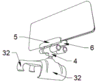
Fig. 1 is a schematic structural diagram of the present invention.
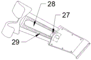
Fig. 2 is a schematic view of the latch structure of the present invention.
Fig. 3 is a schematic structural view of the sun visor of the present invention.
Fig. 4 is a schematic structural diagram of the spring button of the present invention.
Fig. 5 is a schematic view of the ball joint structure of the present invention.
In the figure: a base 1; a ball joint mounting groove 2; a ball joint 3; a rotating member mounting base 4; a first rotating member 5; a second rotating member 6; a mounting groove 7; a sun visor 8; a distance light shielding plate 9; a first knob 20; a second knob 21; a fixing member 25; an adjustment member 26; a chute 27; a slot 28; a latch 29; a spring button 30; a chucking plate 31; a slider 32.
Detailed Description
The technical solutions in the embodiments of the present invention will be described clearly and completely below, and it should be understood that the described embodiments are only some embodiments of the present invention, but not all embodiments. Based on the embodiments in the present invention, all other embodiments obtained by a person skilled in the art without creative work belong to the protection scope of the present invention.
Referring to fig. 1-5, in the embodiment of the present invention, an anti-glare mirror for an automobile includes a base 1; a spherical joint mounting groove 2 is formed in one side of the top of the base 1; a spherical joint 3 is arranged in the spherical joint mounting groove 2; the spherical joint 3 is rotationally matched with the spherical joint mounting groove 2 by three hundred and sixty degrees; the other end of the spherical joint 3 is connected with a rotating part mounting seat 4; the rotating member mounting base 4 is provided with a first rotating member 5 and a second rotating member 6 which are in rotating fit with the rotating member mounting base 4 at intervals; the first rotating piece 5 and the second rotating piece 6 are both provided with mounting grooves 7; a gray sun shield 8 is fixedly mounted on the mounting groove 7 of the first rotating member 5, and a yellow far-shading light plate 9 is mounted on the mounting groove 7 of the second rotating member 6.
Preferably, the rotating member mounting seat 4 is in threaded fit with a first knob 20 and a second knob 21; the first knob 20 is located at one side of the first rotating member 5, and when the first knob 20 is rotated clockwise, the first knob 20 moves towards the first rotating member 5, and finally abuts against the first rotating member 5 to fix the first rotating member 5; the second knob 21 is located at one side of the second rotation member 6, and when the second knob 21 is rotated clockwise, the second knob 21 moves toward the second rotation member 6, and finally abuts against the second rotation member 6 to fix the second rotation member 6.
Preferably, the sun visor 8 and the distance light visor 9 are both long-strip-shaped and sheet-shaped, and the four corners of the sun visor are smoothly processed.
Preferably, the base 1 comprises a fixing member 25 and an adjusting member 26; a long strip-shaped sliding groove 27 is formed inside the fixing piece 25; the adjusting piece 26 is in sliding fit with the sliding groove 27, and a slot 28 penetrating through the adjusting piece 26 is vertically formed at the top of the adjusting piece 26; the slot 28 is in a long strip shape; two clamping teeth 29 are formed at the bottom of the adjusting piece 26; the top of the fixed part 25 is fixedly provided with a spring button 30; the bottom of the spring button 30 is fixedly connected with a clamping plate 31; the clamping plate 31 is positioned in the sliding groove 27 and below the adjusting piece 26; a second latch corresponding to the latch 29 is formed at the top of the latch plate 31; the second latch and latch 29 joint, when pressing spring button 30, spring button 30 is driving joint board 31 and is moving downwards, and the second latch breaks away from the joint with latch 29, and when unclamping spring button 30 back, joint board 31 resets, and second latch and latch 29 resume the joint state.
Preferably, the left end of the bottom of the fixed part 25 and the right end of the bottom of the adjusting part 26 are both formed with a semicircular sliding block 32; the two sliders 32 are disposed opposite to each other.
It is obvious to a person skilled in the art that the invention is not restricted to details of the above-described exemplary embodiments, but that it can be implemented in other specific forms without departing from the spirit or essential characteristics of the invention. The present embodiments are therefore to be considered in all respects as illustrative and not restrictive, the scope of the invention being indicated by the appended claims rather than by the foregoing description, and all changes which come within the meaning and range of equivalency of the claims are therefore intended to be embraced therein.
Claims (5)
1. The anti-dazzle mirror for the automobile is characterized by comprising a base; a spherical joint mounting groove is formed in one side of the top of the base; a spherical joint is arranged in the spherical joint mounting groove; the spherical joint is rotationally matched with the spherical joint mounting groove by three hundred and sixty degrees; the other end of the spherical joint is connected with a rotating piece mounting seat; the rotating piece mounting base is provided with a first rotating piece and a second rotating piece which are in rotating fit with the rotating piece mounting base at intervals; mounting grooves are formed in the first rotating piece and the second rotating piece; the installation groove of the first rotating piece is fixedly provided with a gray sun shield, and the installation groove of the second rotating piece is provided with a yellow far-shading light plate.
2. The automotive anti-glare mirror according to claim 1, wherein the mounting base is in threaded fit with a first knob and a second knob; the first knob is positioned on one side of the first rotating piece, and when the first knob is rotated clockwise, the first knob moves towards the first rotating piece and finally abuts against the first rotating piece to enable the first rotating piece to be fixed; the second knob is located on one side of the second rotating piece, and when the second knob rotates clockwise, the second knob moves towards the direction of the second rotating piece and finally abuts against the second rotating piece to enable the second rotating piece to be fixed.
3. The antiglare mirror for vehicle of claim 1, wherein the sun visor and the light shielding plate are both long strip-shaped and sheet-shaped, and the four corners are rounded.
4. The automotive anti-glare mirror according to claim 1, wherein the base comprises a fixing member and an adjusting member; a strip-shaped chute is formed inside the fixed part; the adjusting piece is in sliding fit with the sliding groove, and a slot penetrating through the adjusting piece is vertically formed in the top of the adjusting piece; grooving to form a long strip; two clamping teeth are formed at the bottom of the adjusting piece; the top of the fixed part is fixedly provided with a spring button; the bottom of the spring button is fixedly connected with a clamping and connecting plate; the clamping plate is positioned in the sliding groove and below the adjusting piece; a second clamping tooth corresponding to the clamping tooth is formed at the top of the clamping plate; second latch and latch joint, when pressing spring button, spring button is driving the joint board and is moving down, and the second latch breaks away from the joint with the latch, and after loosening spring button, the joint board resets, and second latch and latch resume the joint state.
5. The automotive anti-glare mirror according to claim 4, wherein the bottom left end of the fixed member and the bottom right end of the adjusting member are each formed with a semicircular sliding block; the two sliding blocks are oppositely arranged.
Priority Applications (1)
| Application Number | Priority Date | Filing Date | Title |
|---|---|---|---|
| CN201922212260.6U CN211166364U (en) | 2019-12-11 | 2019-12-11 | Anti-dazzle mirror for automobile |
Applications Claiming Priority (1)
| Application Number | Priority Date | Filing Date | Title |
|---|---|---|---|
| CN201922212260.6U CN211166364U (en) | 2019-12-11 | 2019-12-11 | Anti-dazzle mirror for automobile |
Publications (1)
| Publication Number | Publication Date |
|---|---|
| CN211166364U true CN211166364U (en) | 2020-08-04 |
Family
ID=71793586
Family Applications (1)
| Application Number | Title | Priority Date | Filing Date |
|---|---|---|---|
| CN201922212260.6U Expired - Fee Related CN211166364U (en) | 2019-12-11 | 2019-12-11 | Anti-dazzle mirror for automobile |
Country Status (1)
| Country | Link |
|---|---|
| CN (1) | CN211166364U (en) |
-
2019
- 2019-12-11 CN CN201922212260.6U patent/CN211166364U/en not_active Expired - Fee Related
Similar Documents
| Publication | Publication Date | Title |
|---|---|---|
| JPS6250248A (en) | Back mirror | |
| US6224137B1 (en) | Auxiliary sun shield for a front windshield visor | |
| US9669684B2 (en) | Clip on car visor extension | |
| CN211166364U (en) | Anti-dazzle mirror for automobile | |
| GB2235172A (en) | Cassette visor | |
| CN220129922U (en) | Anti-dazzle mirror | |
| US10933723B2 (en) | Apparatuses for reducing light glare and related methods | |
| US3837703A (en) | Glare shields | |
| JP2019093897A (en) | On-vehicle sun visor | |
| CN200974456Y (en) | Vehicular visible anti-dazzle sun-shading board | |
| CN203402066U (en) | Auxiliary rear view mirror of motor vehicle | |
| CN209521517U (en) | Adjustable double-deck sunshading board on automobile | |
| CN206297383U (en) | The anti-dazzle protective spectacles of intelligent Driver anti glare anti static coatingses | |
| CN205768535U (en) | A kind of adjustable sun-shading plate for automobile | |
| CN223355361U (en) | A sun visor | |
| CN223821433U (en) | A sun visor and a vehicle | |
| CN201745416U (en) | Light shading plate capable of changing angles | |
| CN201054049Y (en) | Dazzle-proof dimmer | |
| CN211139171U (en) | Automobile rearview mirror with pitching angle adjusting function | |
| CN215398108U (en) | Built-in sun-shading plate structure for automobile front windshield | |
| CN201366978Y (en) | Anti-glaring lens 360-degree rotation rearview mirror | |
| CN2616417Y (en) | Strong-direct-light-proof shading device for motor vehicle | |
| CN211869118U (en) | Novel automobile sun shield | |
| JP3097711U (en) | Auxiliary sun visor | |
| CN110626151A (en) | Sun shield for automobile |
Legal Events
| Date | Code | Title | Description |
|---|---|---|---|
| GR01 | Patent grant | ||
| GR01 | Patent grant | ||
| CF01 | Termination of patent right due to non-payment of annual fee |
Granted publication date: 20200804 Termination date: 20211211 |
|
| CF01 | Termination of patent right due to non-payment of annual fee |