CN211161486U - Multi-station stamping device for producing automobile metal parts - Google Patents
Multi-station stamping device for producing automobile metal parts Download PDFInfo
- Publication number
- CN211161486U CN211161486U CN201922218058.4U CN201922218058U CN211161486U CN 211161486 U CN211161486 U CN 211161486U CN 201922218058 U CN201922218058 U CN 201922218058U CN 211161486 U CN211161486 U CN 211161486U
- Authority
- CN
- China
- Prior art keywords
- base
- module
- fixed
- fixed mounting
- lower die
- Prior art date
- Legal status (The legal status is an assumption and is not a legal conclusion. Google has not performed a legal analysis and makes no representation as to the accuracy of the status listed.)
- Expired - Fee Related
Links
Images


Abstract
The utility model relates to an auto-parts punching press technical field just discloses car is multistation stamping device for metal accessories production, including fixed baseplate, fixed baseplate's upper end fixed mounting has lower mould base, and fixed mounting has evenly distributed's lower mould device on the lower mould base, and the equal fixed mounting in both ends has the fixed block about lower mould device is inside, and movable mounting has first module between two fixed blocks, and the bottom fixed mounting of first module has first spring. The device drives the upper die base to move downwards through the driving device, the part is punched by the punching block in the upper die base, the first module punches one shape, the second shape is punched when the first module passes through the second module, the first module is rebounded under the action of the first spring after the punching of the upper die, and therefore the part can be extruded, the three modules can work on one part simultaneously, the operation steps are reduced, and the time is saved.
Description
Technical Field
The utility model relates to an auto-parts punching press technical field specifically is multistation stamping device is used in auto-metal parts production.
Background
The stamping is a forming processing method for applying external force to plates, strips, pipes, profiles and the like by a press and a die to cause plastic deformation or separation of the plates, the strips, the pipes, the profiles and the like so as to obtain workpieces (stamping parts) with required shapes and sizes.
The stamping process is characterized in that materials and resources are saved, efficiency is high, technical requirements on operators are not high, products which cannot be achieved by mechanical processing can be manufactured through various die applications, the stamping process is more and more extensive in application, but with the rapid development of the automobile industry, more and more automobile parts are complex in shape and cannot be sequentially stamped, higher requirements on stamping equipment are provided, and in stamping, multi-position stamping cannot be completed, most of the automobile parts only can stamp the upper end of the product, but cannot stamp the side edge, so that a device is needed for stamping the upper end of the product and stamping the side edge of the product.
SUMMERY OF THE UTILITY MODEL
Technical problem to be solved
The utility model provides a not enough to prior art, the utility model provides a multistation stamping device is used in automobile metal accessory production possesses not only can carry out the punching press of upper end to the product, can accomplish simultaneously moreover and carry out the punching press to the side of part, and advantage such as punching press high efficiency has solved present most stamping device and is the problem that needs carry out manual upset to the part at punching press part side.
(II) technical scheme
For realize above-mentioned punching press that not only can carry out the upper end to the product, can accomplish simultaneously moreover and carry out the punching press to the side of part, purpose such as punching press is efficient, the utility model provides a following technical scheme: the multi-station stamping device for producing the metal fittings of the automobiles comprises a fixed base, wherein a lower die base is fixedly arranged at the upper end of the fixed base, lower die devices which are uniformly distributed are fixedly arranged on the lower die base, fixed blocks are fixedly arranged at the left end and the right end inside the lower die device, a first module is movably arranged between the two fixed blocks, a first spring is fixedly arranged at the bottom of the first module, the lower end of the first spring is fixedly arranged at the upper end of a fixed plate, the fixed plate is fixedly arranged at the bottom end inside the lower die device, a second module is fixedly arranged at the top end of the fixed plate, a third module is movably arranged at the front end of the lower die device, a stabilizing base is fixedly arranged at the front end of the third module, a connecting rod is fixedly arranged at the front end of the stabilizing base, the connecting rod is movably arranged inside a fixed, the bottom fixed mounting of going up the mould backup pad has evenly distributed's last mould base, goes up the equal fixed mounting in both ends about the mould base and has the guide bar, goes up the inside movable mounting of mould base and has the punching press piece.
Preferably, the front end of connecting rod extends to fixed frame's inside, and the front end fixed mounting of connecting rod has the limiting plate, and fixed mounting has the second spring between limiting plate and the fixed frame, drives mould base downstream through drive arrangement, goes up the punching press piece in the mould base and carries out the punching press to the part, and first module punching press goes out a shape, and when the second module, the punching press goes out the second shape, and first module is after the punching press of mould, is rebounded under the effect of first spring to can extrude the part.
Preferably, the third module is the tip design, and the third module is installed at the front end of lower mould device, drives the dead lever downstream through drive arrangement, can extrude the stable base when the dead lever downstream, and the slope design of the stable base of deuterogamying to can be with the third module to putting down the extrusion of part, because the third module be the tip design, so can be with the part punching press become required shape.
Preferably, the stabilizing base is designed to be a slope, the fixing frame is fixedly mounted on the right side of the stabilizing base, the stabilizing base is close to the part under the action of the fixing rod, and the stabilizing base is reset under the action of the spring after the part is stamped to prepare for the next action.
Preferably, both ends all fixed mounting have and the stand pipe about the lower mould device, when stamping part downwards at last mould base, the guide bar can get into corresponding stand pipe, has guaranteed the stability in carrying out the punching press, can not let the position of going up mould base and lower mould device take place to deviate.
Preferably, the top end of the upper die base is fixedly installed at the lower end of the driving device, the lower end of the driving device is fixedly installed with a fixing rod corresponding to the upper die base, and the lower end of the fixing rod is designed to be a slope and corresponds to the slope of the stabilizing base.
(III) advantageous effects
Compared with the prior art, the utility model provides a multistation stamping device is used in automobile metal accessory production possesses following beneficial effect:
1. This multistation stamping device is used in automobile metal accessory production, drive through drive arrangement and go up the mould base downstream, go up the punching press piece in the mould base and carry out the punching press to the part, first module punching press goes out a shape, when the second module, the punching press goes out the second shape, first module is after the punching press of mould, by the bounce-back under the effect of first spring, thereby can extrude the part, three module can simultaneous working on a part, the step of operation has been reduced, the time has been saved.
2. This multistation stamping device is used in automobile metal accessory production drives the dead lever downstream through drive arrangement, can extrude when the dead lever downstream and stabilize the base, the slope design of the base is stabilized in the cooperation again to can be with the third module to the extrusion of putting down of part, because the third module be the tip design, so can become the shape that needs with the part punching press, reached and to have carried out the effect of punching press to the part side.
Drawings
FIG. 1 is a front view of the structure of the present invention;
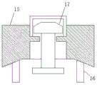
FIG. 2 is a schematic structural view of the upper mold base of the present invention;
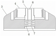
FIG. 3 is a schematic structural view of a lower mold device of the present invention;
Fig. 4 is a schematic structural diagram of a third module of the present invention;
Fig. 5 is a side view of the structure of the present invention.
In the figure: 1 fixed base, 2 lower die bases, 3 lower die devices, 4 fixed blocks, 5 first modules, 6 first springs, 7 fixed plates, 8 second modules, 9 third modules and 10 Stabilization The device comprises a base, 11 connecting rods, 12 fixing frames, 13 supporting rods, 14 upper die supporting rods, 15 upper die bases, 16 guide rods, 17 stamping blocks, 18 limiting plates, 19 second springs, 20 driving devices and 21 fixing rods.
Detailed Description
The technical solutions in the embodiments of the present invention will be described clearly and completely with reference to the accompanying drawings in the embodiments of the present invention, and it is obvious that the described embodiments are only some embodiments of the present invention, not all embodiments. Based on the embodiments in the present invention, all other embodiments obtained by a person skilled in the art without creative work belong to the protection scope of the present invention.
Referring to fig. 1-5, the multi-station stamping device for producing metal fittings of automobiles comprises a fixed base 1, a lower die base 2 is fixedly installed at the upper end of the fixed base 1, lower die devices 3 which are uniformly distributed are fixedly installed on the lower die base 2, guide pipes are fixedly installed at the left and right ends of the lower die devices 3, when parts are stamped downwards by an upper die base 15, guide rods 16 enter the corresponding guide pipes to ensure stability in the stamping process and prevent the positions of the upper die base 15 and the lower die devices from deviating, fixed blocks 4 are fixedly installed at the left and right ends inside the lower die devices 3, a first module 5 is movably installed between the two fixed blocks 4, a first spring 6 is fixedly installed at the bottom of the first module, the lower end of the first spring 6 is fixedly installed at the upper end of a fixed plate 7, and the fixed plate 7 is fixedly installed at the bottom inside the lower die devices 3, the top end of the fixed plate 7 is fixedly provided with a second module 8, the front end of the lower die device 3 is movably provided with a third module 9, the third module 9 is in a pointed design, the third module 9 is arranged at the front end of the lower die device 3, the fixed rod 21 is driven by the driving device 20 to move downwards, the fixed rod 21 can extrude the stabilizing base 10 while moving downwards, the stabilizing base 10 is in a slope design, the right side of the stabilizing base 10 is fixedly provided with a fixed frame 12, the stabilizing base 10 can approach to the direction of a part under the action of the fixed rod 21 and can be reset under the action of a spring after the part is stamped, the next action is prepared, the slope design of the stabilizing base 10 is matched, so that the third module 9 can be put down and extruded to the part, the part can be stamped into a required shape due to the pointed design of the third module 9, the front end of the third module 9 is fixedly provided with the stabilizing base 10, the front end of the stabilizing base 10 is fixedly provided with a connecting rod 11, the front end of the connecting rod 11 extends into the fixing frame 12, the front end of the connecting rod 11 is fixedly provided with a limiting plate 18, a second spring 19 is fixedly arranged between the limiting plate 18 and the fixing frame 12, the upper die base 15 is driven to move downwards by a driving device 20, the top end of the upper die base 15 is fixedly arranged at the lower end of the driving device 20, the lower end of the driving device 20 is fixedly provided with a fixing rod 21 corresponding to the upper die base 15, the lower end of the fixing rod 21 is designed to be a slope and corresponds to the slope of the stabilizing base 10, a stamping block 17 in the upper die base 15 stamps parts, the first module 5 stamps out one shape, when the first module passes through the second module 8, the second shape is stamped out, the first module 5 is rebounded under the action of the first spring 6 after being stamped out of the upper die 15, connecting rod 11 movable mounting has bracing piece 13 in the inside of fixed frame 12, and the equal fixed mounting in both ends has bracing piece 13 about lower mould base 2, and the upper end fixed mounting of bracing piece 13 has last mould backup pad 14, and the bottom fixed mounting who goes up mould backup pad 14 has evenly distributed's last mould base 15, goes up the equal fixed mounting in both ends about mould base 15 and has guide bar 16, and the inside movable mounting who goes up mould base 15 has punching press piece 17.
The working principle is as follows: when in use, the driving device 20 drives the upper die base 15 to move downwards, the stamping block 17 in the upper die base 15 stamps the parts, the first die block 5 stamps a shape, while passing through the second die block 8, a second shape is stamped, the first die block 5, after being stamped by the upper die 15, the part can be extruded by rebounding under the action of the first spring 6, the three modules can work on one part at the same time, the operation steps are reduced, the time is saved, the fixing rod 21 moves downwards, the fixing rod 21 can extrude the stabilizing base 10 when moving downwards, and then the slope design of the stabilizing base 10 is matched, so that the third module 9 can be pressed down towards the part, because the third module 9 is of pointed design, therefore, the part can be punched into a required shape, and the effect of punching the side edge of the part is achieved.
To sum up, this multistation stamping device is used in automobile metal accessory production can be with the part punching press out our desired shape simultaneously through last mould and the lower mould that has changed the punching press, and first module 5, second module 8, third module 9 are mated again, have practiced thrift production line length and place, have also accelerated the speed of production simultaneously.
Although embodiments of the present invention have been shown and described, it will be appreciated by those skilled in the art that changes, modifications, substitutions and alterations can be made in these embodiments without departing from the principles and spirit of the invention, the scope of which is defined in the appended claims and their equivalents.
Claims (6)
1. Multistation stamping device is used in automobile metal accessory production, including fixed baseplate (1), its characterized in that: the upper end of the fixed base (1) is fixedly provided with a lower die base (2), the lower die base (2) is fixedly provided with a lower die device (3) which is uniformly distributed, the left end and the right end of the interior of the lower die device (3) are fixedly provided with fixed blocks (4), a first module (5) is movably arranged between the two fixed blocks (4), the bottom of the first module is fixedly provided with a first spring (6), the lower end of the first spring (6) is fixedly arranged at the upper end of a fixed plate (7), the fixed plate (7) is fixedly arranged at the bottom end of the interior of the lower die device (3), the top of the fixed plate (7) is fixedly provided with a second module (8), the front end of the lower die device (3) is movably provided with a third module (9), the front end of the third module (9) is fixedly provided with a stabilizing base (10), and the front, connecting rod (11) movable mounting has bracing piece (13) in the inside of fixed frame (12), the equal fixed mounting in both ends has in the left and right sides of lower mould base (2), the upper end fixed mounting of bracing piece (13) has last mould backup pad (14), the bottom fixed mounting who goes up mould backup pad (14) has evenly distributed's last mould base (15), the equal fixed mounting in both ends has guide bar (16) about last mould base (15), the inside movable mounting who goes up mould base (15) has punching press piece (17).
2. The multi-station stamping device for producing the automobile metal fittings as claimed in claim 1, wherein: the front end of connecting rod (11) extends to the inside of fixed frame (12), and the front end fixed mounting of connecting rod (11) has limiting plate (18), and fixed mounting has second spring (19) between limiting plate (18) and fixed frame (12).
3. The multi-station stamping device for producing the automobile metal fittings as claimed in claim 1, wherein: the third module (9) is of pointed design.
4. The multi-station stamping device for producing the automobile metal fittings as claimed in claim 1, wherein: the stabilization base (10) is of ramp design.
5. The multi-station stamping device for producing the automobile metal fittings as claimed in claim 1, wherein: the left end and the right end of the lower die device (3) are fixedly provided with guide pipes.
6. The multi-station stamping device for producing the automobile metal fittings as claimed in claim 1, wherein: the top end of the upper die base (15) is fixedly installed at the lower end of the driving device (20), the lower end of the driving device (20) is fixedly installed with a fixing rod (21) corresponding to the upper die base (15), and the lower end of the fixing rod (21) is designed to be a slope and corresponds to the slope of the stabilizing base (10).
Priority Applications (1)
| Application Number | Priority Date | Filing Date | Title |
|---|---|---|---|
| CN201922218058.4U CN211161486U (en) | 2019-12-12 | 2019-12-12 | Multi-station stamping device for producing automobile metal parts |
Applications Claiming Priority (1)
| Application Number | Priority Date | Filing Date | Title |
|---|---|---|---|
| CN201922218058.4U CN211161486U (en) | 2019-12-12 | 2019-12-12 | Multi-station stamping device for producing automobile metal parts |
Publications (1)
| Publication Number | Publication Date |
|---|---|
| CN211161486U true CN211161486U (en) | 2020-08-04 |
Family
ID=71793335
Family Applications (1)
| Application Number | Title | Priority Date | Filing Date |
|---|---|---|---|
| CN201922218058.4U Expired - Fee Related CN211161486U (en) | 2019-12-12 | 2019-12-12 | Multi-station stamping device for producing automobile metal parts |
Country Status (1)
| Country | Link |
|---|---|
| CN (1) | CN211161486U (en) |
-
2019
- 2019-12-12 CN CN201922218058.4U patent/CN211161486U/en not_active Expired - Fee Related
Similar Documents
| Publication | Publication Date | Title |
|---|---|---|
| CN103350152B (en) | Punching machine with automatic feeding function | |
| CN213002076U (en) | Stamping die who facilitates use | |
| CN211161486U (en) | Multi-station stamping device for producing automobile metal parts | |
| CN108097807A (en) | A kind of processing unit (plant) of sheet metal member automation side punching bending and forming integral type | |
| CN211218208U (en) | Stamping device for hardware manufacturing | |
| CN217432795U (en) | Die ejection device for punch forming equipment | |
| CN115532966A (en) | Metal processing continuous stamping device and stamping method thereof | |
| CN114289627A (en) | Automatic demolding and stamping equipment for automobile parts | |
| CN214820095U (en) | Plastic casing mold processing | |
| CN214108509U (en) | Automatic panel stamping die of material loading | |
| CN113369380A (en) | Steel strip and manufacturing process thereof | |
| CN215965718U (en) | Freezer door plate bending and forming equipment | |
| CN217141840U (en) | Bending device for open type fixed table press | |
| CN217191971U (en) | Automatic waste discharge device for stamping | |
| CN214768240U (en) | Positioning device for punching of cathode frame transverse tube | |
| CN216369905U (en) | Hardware stamping device with automatic discharging function | |
| CN205085289U (en) | Mold processing of open hasp of steel band for packaging | |
| CN212285509U (en) | High-efficient sheet metal component general mould that punches a hole | |
| CN216679880U (en) | Stamping die machine tool capable of quickly positioning die | |
| CN214639444U (en) | Automatic demolding and stamping die for automobile front floor | |
| CN216655951U (en) | Stamping equipment of low defective percentage | |
| CN220092782U (en) | Bending die with return bending part | |
| CN208840310U (en) | The automatic punching device of L-shape spanner | |
| CN218134416U (en) | Multi-station stamping die for machining expansion sleeve | |
| CN219966142U (en) | Square metal section cold press molding device |
Legal Events
| Date | Code | Title | Description |
|---|---|---|---|
| GR01 | Patent grant | ||
| GR01 | Patent grant | ||
| CF01 | Termination of patent right due to non-payment of annual fee | ||
| CF01 | Termination of patent right due to non-payment of annual fee |
Granted publication date: 20200804 Termination date: 20211212 |