CN211147094U - A dehydration mechanism for scutching machine - Google Patents
A dehydration mechanism for scutching machine Download PDFInfo
- Publication number
- CN211147094U CN211147094U CN201921807154.6U CN201921807154U CN211147094U CN 211147094 U CN211147094 U CN 211147094U CN 201921807154 U CN201921807154 U CN 201921807154U CN 211147094 U CN211147094 U CN 211147094U
- Authority
- CN
- China
- Prior art keywords
- frame
- dehydration
- drying
- stoving
- cloth
- Prior art date
- Legal status (The legal status is an assumption and is not a legal conclusion. Google has not performed a legal analysis and makes no representation as to the accuracy of the status listed.)
- Active
Links
- 230000018044 dehydration Effects 0.000 title claims abstract description 47
- 238000006297 dehydration reaction Methods 0.000 title claims abstract description 47
- 239000004744 fabric Substances 0.000 claims abstract description 26
- 238000001035 drying Methods 0.000 claims abstract description 25
- 238000001125 extrusion Methods 0.000 claims abstract description 19
- 238000005192 partition Methods 0.000 claims description 7
- 239000002918 waste heat Substances 0.000 abstract description 2
- 238000010438 heat treatment Methods 0.000 description 4
- 238000000034 method Methods 0.000 description 4
- XLYOFNOQVPJJNP-UHFFFAOYSA-N water Substances O XLYOFNOQVPJJNP-UHFFFAOYSA-N 0.000 description 4
- 238000004043 dyeing Methods 0.000 description 2
- 238000001704 evaporation Methods 0.000 description 2
- 239000004753 textile Substances 0.000 description 2
- 230000005540 biological transmission Effects 0.000 description 1
- 238000004061 bleaching Methods 0.000 description 1
- 238000009990 desizing Methods 0.000 description 1
- 230000008020 evaporation Effects 0.000 description 1
- 230000004048 modification Effects 0.000 description 1
- 238000012986 modification Methods 0.000 description 1
- 238000006213 oxygenation reaction Methods 0.000 description 1
- 238000005406 washing Methods 0.000 description 1
Images


Abstract
The utility model discloses a dewatering mechanism for scutching machine, put up, dry including dehydration, the frame of drying, the both sides of drying frame and dehydration frame all are equipped with the logical groove that supplies the cloth to pass through, the pivot has the extrusion rod in the dehydration frame, the roof that the frame of drying is opening decurrent segmental arc and horizontal segment, and the top of horizontal segment is equipped with the inlet scoop, the inlet scoop communicates with each other through output pipeline and the air pump input of locating the frame outside of drying, and the output of air pump leads to the inside to the frame of drying through input pipeline. The utility model relates to a dewatering mechanism for scutching machine better must realize the dehydration through setting up heater and air pump in relative confined stoving frame to can discharge inside steam fast, this steam that has certain waste heat simultaneously can be arranged to preheat the cloth in the dehydration frame, make full use of heat energy, secondly can keep drying lower humidity in the frame, the utilization ratio of energy is bigger, and the efficiency of cloth dehydration is higher.
Description
Technical Field
The utility model relates to a textile machinery equipment technical field specifically is a dewatering mechanism for scutching machine.
Background
In the textile printing and dyeing process, the fabric has the processing procedures of rope-shaped cloth in the procedures of desizing, bleaching, dyeing and washing after printing, the cloth is generally scutched through a scutching machine before entering the next procedure, and the cloth is dehydrated before scutching. The cloth with high water content has high quality, increases the cloth transmission pressure of the scutching machine, and meanwhile, the cloth with water is easy to adhere to each other, so that the scutching machine is inconvenient to scutch.
As patent numbers: 201721371272.8, entitled "dewatering mechanism of scutcher", including the dehydration frame, the dehydration frame is provided with feeding ring and dehydration delivery roll, and dehydration frame inner chamber is provided with dehydration roller and lower dehydration roller, goes up dehydration roller and is the level setting down, and the dehydration frame still is provided with the stoving subassembly, mainly dehydrates cloth through a plurality of dehydration rollers that set up, and subsidiary steam heats the evaporation. However, the device is exposed to the outside, so that the heating effect is poor on one hand, the dehydration efficiency is not high, the heat is easy to dissipate and is large on the other hand, and meanwhile, the steam after the cloth is heated still has high preheating and is not used, so that the energy loss is large.
In order to solve the problems, the scheme is developed accordingly.
SUMMERY OF THE UTILITY MODEL
Technical problem to be solved
An object of the utility model is to overcome prior art's not enough, provide a dehydration mechanism for scutching machine that has higher dehydration efficiency and higher energy usage rate.
(II) technical scheme
In order to achieve the above purpose, the utility model discloses a following technical scheme realizes: the utility model provides a dewatering mechanism for scutching machine, includes dehydration frame, stoving frame, the both sides of stoving frame and dehydration frame all are equipped with the logical groove that supplies the cloth to pass through, the pivot has the extrusion rod in the dehydration frame, the roof of stoving frame is opening decurrent segmental arc and horizontal segment, and the top of horizontal segment is equipped with the inlet scoop, the inlet scoop communicates with each other through output pipeline and the air pump input of locating stoving frame outside, and the output of air pump leads to the inside of dehydration frame through input pipeline, be equipped with the multiunit deflector roll of arranging along its length direction in the stoving frame, the lateral part of every group deflector roll be equipped with the communicating tuber pipe of fan, the bottom of stoving frame is equipped with the heater.
Preferably, the dehydration frame is divided into two layers by a partition plate, the upper layer is used for accommodating the extrusion rod, the end part of the input conduit is communicated with the inner part of the lower layer, and the partition plate is provided with a through hole.
Preferably, it is equipped with a plurality ofly to go out the tuber pipe, and is located the frame inside of drying, and the fan is located the frame outside of drying, it all is rectangular form all to go out the corresponding air outlet of tuber pipe, and is located the top of deflector roll in vertical direction.
Preferably, the extrusion rods are provided with a plurality of groups, two of the extrusion rods are taken as a group, and the two groups are sequentially arranged along the length direction of the dewatering frame in a curve shape.
Preferably, the drying rack is wider than the guide roller, and the heater is located right below the guide roller.
Preferably, the highest position of the arc-shaped section in the top wall of the drying rack is connected with the horizontal section, the lowest position of the arc-shaped section is connected with the extrusion rack, and the opening of the arc-shaped section is downward.
(III) advantageous effects
After the technical scheme is adopted, compared with the prior art, the utility model, possess following advantage: the utility model relates to a dewatering mechanism for scutching machine better must realize the dehydration through setting up heater and air pump in relative confined stoving frame to can discharge inside steam fast, this steam that has certain waste heat simultaneously can be arranged to preheat the cloth in the dehydration frame, make full use of heat energy, secondly can keep drying lower humidity in the frame, the utilization ratio of energy is bigger, and the efficiency of cloth dehydration is higher.
Drawings
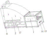
FIG. 1 is a schematic view of the present invention;
fig. 2 is a side view of the present invention;
fig. 3 is a sectional side view of the structure of the middle drying rack of the present invention.
In the figure: the device comprises a dehydration frame 1, a drying frame 2, a through groove 3, an extrusion rod 4, an arc section 5, a horizontal section 6, an air suction opening 7, an output pipeline 8, an air pump 9, an input pipeline 10, a guide roller 11, an air outlet pipe 12, a heater 13, a partition plate 14, a through hole 15, an air outlet 16 and a fan 17.
Detailed Description
The invention is explained in more detail below with reference to the figures and examples.
As shown in fig. 1-3: the utility model provides a dewatering mechanism for scutching machine, includes dehydration frame 1, dries and puts up 2 and all is equipped with the logical groove 3 that supplies the cloth to pass through with the both sides of dehydration frame 1, and the pivot has extrusion rod 4 in the dehydration frame 1, and extrusion rod 4 is equipped with the multiunit, and uses two to be a set of, is the curvilinear figure along the length direction of dehydration frame 1 and arranges in proper order.
The pressing roller 4 arranged in a curve shape mainly aims at increasing the travel of the cloth in the dewatering frame 1, and the same occupation size stays for a longer time so as to be convenient for heating the cloth (the steam allowance is heated, and the specific mode is shown as follows).
The roof of stoving frame 2 is the decurrent segmental arc 5 of opening and horizontal segment 6, and wherein 5 highest departments of segmental arc in the 2 roof of stoving frame link up with horizontal segment 6, and the lowest department links up with the extrusion frame, and the opening of this segmental arc 5 is downward. An air suction opening 7 is arranged above the horizontal section 6, the air suction opening 7 is communicated with an input end of an air pump 9 arranged outside the drying rack 2 through an output pipeline 8, an output end of the air pump 9 is communicated with the inside of the dewatering rack 1 through an input pipeline 10, a plurality of groups of guide rollers 11 arranged along the length direction of the drying rack 2 are arranged in the drying rack 2, a wind outlet pipe 12 communicated with a fan 17 is arranged on the side part of each group of guide rollers 11, and a heater 13 is arranged at the bottom of the drying rack 2.
The air pump 9 in the scheme needs to be high-temperature resistant, and the vortex air pump 9 with the model of XGB712-3KW and the Aileide oxygenation high-temperature-resistant explosion-proof high-pressure fan 17 can be selected.
Because when the first time gets into stoving frame 2, the cloth is lower through the heat of heating, and moves to when deriving stoving frame 2 soon, and the temperature of cloth reaches the extreme point, consequently is the biggest because of the output of heating back steam in the cloth of this section, so this scheme is here to dry and put up 2 and establish to the highest point that links up the arc end, and the holding steam of a bigger amount, the increase of being convenient for is discharged two times.
Set up air pump 9 in this scheme, mainly used is quick with inside steam discharge to lead to and preheat the cloth in dehydration frame 1, make full use of heat energy, secondly can keep the humidity in the frame of drying 2 (moisture in the hot steam mainly comes from wet cloth), better must realize the dehydration in frame of drying 2 that seals relatively, and the utilization ratio of energy can reach the maximize.
Set up air outlet 16 in stoving frame 2 both sides, set up inlet scoop 7 at the top for hot steam forms a thermal cycle from bottom to top in the box, wherein can flow at arc roof department hot steam and conduct to leveling roof department, and finally assemble and discharge by inlet scoop 7 leveling roof department.
The dehydration frame 1 is divided into two layers by a partition plate 14, the upper layer is used for accommodating the extrusion rod 4, the end part of the input conduit is communicated to the inner part of the lower layer, and the partition plate 14 is provided with a through hole 15.
Because the cloth is more at dehydration frame 1 after 4 extrusion of extrusion rod, consequently the baffle 14 setting in this scheme dehydration frame 1 is mainly in order to avoid arousing equipment trouble in the input pipeline 10 that leads to dehydration frame 1 from the lateral wall inflow of dehydration frame 1 after the water through the through-hole 15 water conservancy diversion on baffle 14 after will extruding (also can avoid setting up baffle 14 through letting in dehydration frame 1 with input pipeline 10 downward sloping ground in this scheme).
The air outlet pipe 12 is provided with a plurality of air outlets and is positioned inside the drying frame 2, the fan 17 is positioned outside the drying frame 2, and the air outlet 16 corresponding to the air outlet pipe 12 is in a long strip shape and is positioned above the guide roller 11 in the vertical direction. The air outlet pipe 12 is mainly arranged to accelerate the steam generated by evaporating the moisture on the cloth to be quickly blown to the air suction opening 7, so that the steam is quickly discharged.
The drying rack 2 has a width greater than that of the guide roller 11, and the heater 13 is positioned right below the guide roller 11.
In light of the foregoing, it will be apparent to those skilled in the art from this disclosure that various changes and modifications can be made without departing from the spirit and scope of the invention. The technical scope of the present invention is not limited to the content of the specification, and the protection scope must be determined by the scope of the claims.
Claims (6)
1. The utility model provides a dewatering mechanism for scutching machine, includes dehydration frame, stoving frame, the stoving frame all is equipped with the logical groove that supplies the cloth to pass through with the both sides of dehydration frame, the pivot has extrusion rod, its characterized in that in the dehydration frame: the roof of stoving frame is decurrent segmental arc and the horizontal segment of opening, and the top of horizontal segment is equipped with the inlet scoop, the inlet scoop communicates with each other through output pipeline and the air pump input of locating stoving frame outside, and the output of air pump leads to the inside to the dehydration frame through input pipeline, the stoving is put up and is equipped with the multiunit deflector roll of arranging along its length direction, and the lateral part of every group deflector roll is equipped with the tuber pipe that goes out with the fan communicates with each other, the bottom of stoving frame is equipped with the heater.
2. The dewatering mechanism for a scutcher according to claim 1, wherein: the dehydration frame is divided into two layers by a partition plate, the upper layer is used for accommodating the extrusion rod, the end part of the input conduit is communicated with the inner part of the lower layer, and the partition plate is provided with a through hole.
3. The dewatering mechanism for a scutcher according to claim 1, wherein: the air outlet pipe is provided with a plurality of air outlets, is located inside the drying frame, is located outside the drying frame, and is in a long strip shape at the corresponding air outlet of the air outlet pipe and is located above the guide roller in the vertical direction.
4. The dewatering mechanism for a scutcher according to claim 1, wherein: the extrusion rods are provided with a plurality of groups, two extrusion rods are used as a group, and the two extrusion rods are sequentially arranged in a curve shape along the length direction of the dehydration frame.
5. The dewatering mechanism for a scutcher according to claim 1, wherein: the width of drying frame is greater than the width of deflector roll, and the heater is located the deflector roll under.
6. The dewatering mechanism for a scutcher according to claim 1, wherein: the segmental arc highest point in the stoving frame roof links up with the horizontal segment, and the lowest is linked up with the extrusion frame, and the opening of this segmental arc is downward.
Priority Applications (1)
| Application Number | Priority Date | Filing Date | Title |
|---|---|---|---|
| CN201921807154.6U CN211147094U (en) | 2019-10-25 | 2019-10-25 | A dehydration mechanism for scutching machine |
Applications Claiming Priority (1)
| Application Number | Priority Date | Filing Date | Title |
|---|---|---|---|
| CN201921807154.6U CN211147094U (en) | 2019-10-25 | 2019-10-25 | A dehydration mechanism for scutching machine |
Publications (1)
| Publication Number | Publication Date |
|---|---|
| CN211147094U true CN211147094U (en) | 2020-07-31 |
Family
ID=71768015
Family Applications (1)
| Application Number | Title | Priority Date | Filing Date |
|---|---|---|---|
| CN201921807154.6U Active CN211147094U (en) | 2019-10-25 | 2019-10-25 | A dehydration mechanism for scutching machine |
Country Status (1)
| Country | Link |
|---|---|
| CN (1) | CN211147094U (en) |
-
2019
- 2019-10-25 CN CN201921807154.6U patent/CN211147094U/en active Active
Similar Documents
| Publication | Publication Date | Title |
|---|---|---|
| CN107974786B (en) | Printing and dyeing equipment | |
| CN208668063U (en) | The shaping and drying device of jacquard fabric | |
| CN111271943A (en) | Cloth drying and dewatering device for textile processing | |
| CN110735262A (en) | non-woven fabric drying system with ironing effect | |
| CN213086335U (en) | Extrusion dewatering device for textile fabric dyeing and finishing assembly line | |
| CN207147151U (en) | The drying unit of fabric dyeing machine | |
| CN211147094U (en) | A dehydration mechanism for scutching machine | |
| CN207471987U (en) | Cloth drying device | |
| CN109402907A (en) | A kind of reactive dye carry out the device of salt-free dyeing to un-scoured and unbleached cotton textile | |
| CN104913623A (en) | Spinning fabric energy-saving dryer | |
| CN111321537A (en) | Drying device for dip dyeing and desizing of woven fabric | |
| CN209211162U (en) | A kind of cleaning paper grade (stock) paper drying unit | |
| CN211112679U (en) | Dyeing machine goes out cloth stoving winding mechanism | |
| CN208012313U (en) | A kind of cloth drying device for producing underpants | |
| CN213066960U (en) | Air duct circulating box of hot air tentering setting machine | |
| CN204730611U (en) | A kind of woven fabric energy-saving dryer | |
| CN205133983U (en) | Reduction steam ager | |
| CN211596040U (en) | Printing and dyeing equipment for textile processing | |
| CN211171255U (en) | Fabric pre-shrinking machine | |
| CN218915775U (en) | Drying device for textile printing and dyeing | |
| CN111365949A (en) | Fabric drying device | |
| CN219820380U (en) | Air distribution plate of dryer for chlorinated polyethylene | |
| CN215571913U (en) | Drying equipment for textile processing | |
| CN220689695U (en) | Drying equipment for printing and dyeing | |
| CN208072054U (en) | A kind of good cloth drying machine of drying effect |
Legal Events
| Date | Code | Title | Description |
|---|---|---|---|
| GR01 | Patent grant | ||
| GR01 | Patent grant | ||
| TR01 | Transfer of patent right | ||
| TR01 | Transfer of patent right |
Effective date of registration: 20231109 Address after: Room 217, Building A2, No. 6 Industrial Road (Headquarters Economic Office Area), Wuji Town, Shuyang County, Suqian City, Jiangsu Province, 223700 Patentee after: Jiangsu Shengbai Construction Engineering Co.,Ltd. Address before: 312500 No. 18, Guodao East Road, Ru'ao Town, Xinchang County, Shaoxing City, Zhejiang Province Patentee before: Zhejiang Yuefeng intelligent electromechanical Co.,Ltd. |