CN211111331U - Rotatory aquaculture aeration equipment of over-and-under type - Google Patents
Rotatory aquaculture aeration equipment of over-and-under type Download PDFInfo
- Publication number
- CN211111331U CN211111331U CN201921895855.XU CN201921895855U CN211111331U CN 211111331 U CN211111331 U CN 211111331U CN 201921895855 U CN201921895855 U CN 201921895855U CN 211111331 U CN211111331 U CN 211111331U
- Authority
- CN
- China
- Prior art keywords
- aeration
- aquaculture
- rotary
- pipe
- mounting panel
- Prior art date
- Legal status (The legal status is an assumption and is not a legal conclusion. Google has not performed a legal analysis and makes no representation as to the accuracy of the status listed.)
- Expired - Fee Related
Links
Images


Classifications
-
- Y—GENERAL TAGGING OF NEW TECHNOLOGICAL DEVELOPMENTS; GENERAL TAGGING OF CROSS-SECTIONAL TECHNOLOGIES SPANNING OVER SEVERAL SECTIONS OF THE IPC; TECHNICAL SUBJECTS COVERED BY FORMER USPC CROSS-REFERENCE ART COLLECTIONS [XRACs] AND DIGESTS
- Y02—TECHNOLOGIES OR APPLICATIONS FOR MITIGATION OR ADAPTATION AGAINST CLIMATE CHANGE
- Y02W—CLIMATE CHANGE MITIGATION TECHNOLOGIES RELATED TO WASTEWATER TREATMENT OR WASTE MANAGEMENT
- Y02W10/00—Technologies for wastewater treatment
- Y02W10/10—Biological treatment of water, waste water, or sewage
Landscapes
- Farming Of Fish And Shellfish (AREA)
Abstract
The utility model relates to the technical field of aquaculture, in particular to a lifting rotary aquaculture aeration device, which comprises a float, wherein two fixed plates which are arranged in a cross way are arranged above the float; the lifting type rotary aquaculture aeration device adjusts the depth of the rotary aeration mechanism through the fixed plate, the connecting mechanism and the like, so that the rotary aeration mechanism has a lifting function, is suitable for culture ponds with different depths, and solves the problem of the diving depth of the existing submersible aeration device; this rotatory aquaculture aeration equipment of over-and-under type is through the support frame, rotatory aeration mechanism and the mechanism of admitting air that are equipped with, and the oxygen in the bubble of being convenient for dissolves in aquatic rapidly, has changed traditional aeration mechanism and has leaded to the poor situation of aeration efficiency because of static work, has solved the problem of current dive formula aeration equipment's aeration inefficiency.
Description
Technical Field
The utility model relates to an aquaculture technical field specifically is a rotatory aquaculture aeration equipment of over-and-under type.
Background
In order to ensure the oxygen content in the water body, aquaculture personnel need to use an aeration device to carry out oxygen aeration on the water body, wherein the aeration device comprises water aeration and submersible aeration; the existing submersible aeration device has the following defects: on one hand, the diving depth of the submersible aeration device can not be adjusted, and the submersible aeration device can not be suitable for culture ponds with different depths, and on the other hand, the existing submersible aeration device is still in a water body during aeration, so that the oxygenation efficiency of the water body is low.
SUMMERY OF THE UTILITY MODEL
An object of the utility model is to provide a rotatory aquaculture aeration equipment of over-and-under type to the dive degree of depth of the current dive aeration equipment who provides in solving above-mentioned background art can not adjust and current dive aeration equipment's the problem of aeration inefficiency.
In order to achieve the above object, the utility model provides a following technical scheme:
a lifting type rotary aquaculture aeration device comprises a buoy, wherein two fixing plates which are arranged in a crossed mode are arranged above the buoy, two connecting mechanisms which are parallel to each other are arranged on the fixing plates, a supporting frame is arranged below the fixing plates, a rotary aeration mechanism is arranged on the supporting frame, and an air inlet mechanism is arranged between the supporting frame and the fixing plates; the buoy is of a hollow structure; through holes are formed in the fixing plate close to the two ends, and the two ends of the fixing plate are fixedly connected with the floating barrel through bolts; the connecting mechanism comprises a threaded rod, the threaded rod penetrates through the corresponding through hole, a nut is connected to the threaded rod in a threaded mode, and the nut is located above the buoy; the support frame includes two mounting panels that are parallel to each other, two be equipped with four pillars between the mounting panel, the pillar is located the four corners department of mounting panel, the bottom of threaded rod with be located the top mounting panel fixed connection is located the below the bottom surface of mounting panel passes through bolt fixedly connected with motor.
Preferably, the peripheral outer wall of the buoy is tightly bonded with hanging rings which are distributed at equal intervals.
Preferably, a plurality of water permeable holes are formed in the mounting plate in a matrix distribution manner.
Preferably, the rotary aeration mechanism comprises two aeration discs positioned between the two mounting plates, the aeration discs are rotatably connected with the top surfaces of the mounting plates positioned below through bearings, the output shaft of the motor penetrates through the mounting plates positioned below and is fixedly connected with the aeration discs coaxially, each aeration disc is of a hollow structure, a plurality of blades are annularly and equidistantly distributed on the outer circumferential wall of each aeration disc, a plurality of air holes are annularly and equidistantly distributed on the outer circumferential wall of each aeration disc, and the interiors of the aeration discs are communicated with the air holes.
Preferably, the mechanism of admitting air includes from last to being vertical intake pipe, flexible pipe and the connecting pipe that is equipped with in proper order down, flexible pipe both ends respectively with the intake pipe with the connecting pipe closely bonds, just the intake pipe flexible pipe with the connecting pipe is linked together in proper order, the intake pipe inlays to be established two the intersection of fixed plate, the connecting pipe passes and is located the top the mounting panel, the bottom of connecting pipe through the bearing with the aeration dish rotates to be connected, just the connecting pipe with the inside of aeration dish is linked together.
Preferably, the overall shape of the telescopic tube is spiral.
Preferably, the aeration disc has a drum shape as a whole.
Compared with the prior art, the beneficial effects of the utility model are that:
1. the lifting type rotary aquaculture aeration device adjusts the depth of the threaded rod extending into the water body by the aid of the fixed plate, the connecting mechanism and the like, namely, the nut is rotated to adjust the depth of the rotary aeration mechanism, so that the rotary aeration mechanism has a lifting function, is suitable for culture ponds with different depths, and solves the problem of the diving depth of the conventional submersible aeration device;
2. this rotatory aquaculture aeration equipment of over-and-under type is through the support frame that is equipped with, rotatory aeration mechanism and air inlet mechanism, the air supply enters into in rotatory aeration mechanism and oxygenates the water through air inlet mechanism promptly, and the motor that is equipped with drives the aeration dish and rotates, thereby make the bubble that the gas pocket produced throw away with higher speed, and then the oxygen in the bubble of being convenient for is dissolved in aquatic rapidly, traditional aeration mechanism has been changed and has leaded to the poor situation of aeration efficiency because of static work, the problem of current dive formula aeration equipment's aeration inefficiency has been solved.
Drawings
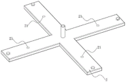
Fig. 1 is a schematic view of the overall structure of the present invention;
FIG. 2 is a schematic view of a part of the structure of the present invention;
fig. 3 is a schematic structural view of the connection mechanism of the present invention;
fig. 4 is a schematic structural view of a fixing plate of the present invention;
FIG. 5 is a schematic structural view of the middle buoy of the present invention;
fig. 6 is a schematic structural view of the support frame of the present invention;
fig. 7 is a schematic structural view of the middle aeration mechanism of the present invention.
In the figure: 1. a float bowl; 11. hanging a ring; 2. a fixing plate; 21. a through hole; 3. a connecting mechanism; 31. a threaded rod; 32. a nut; 4. a support frame; 41. mounting a plate; 411. water permeable holes; 42. a pillar; 5. rotating the aeration mechanism; 51. an aeration disc; 511. air holes; 52. a paddle; 6. an air intake mechanism; 61. an air inlet pipe; 62. a telescopic pipe; 63. a connecting pipe; 7. an electric motor.
Detailed Description
The technical solutions in the embodiments of the present invention will be described clearly and completely with reference to the accompanying drawings in the embodiments of the present invention, and it is obvious that the described embodiments are only some embodiments of the present invention, not all embodiments. Based on the embodiments in the present invention, all other embodiments obtained by a person skilled in the art without creative work belong to the protection scope of the present invention.
In the description of the present invention, it is to be understood that the terms "center", "longitudinal", "lateral", "length", "width", "thickness", "upper", "lower", "front", "rear", "left", "right", "vertical", "horizontal", "top", "bottom", "inner", "outer", "clockwise", "counterclockwise", and the like indicate orientations or positional relationships based on the orientations or positional relationships shown in the drawings, and are only for convenience of description and to simplify the description, but do not indicate or imply that the device or element referred to must have a particular orientation, be constructed and operated in a particular orientation, and therefore should not be construed as limiting the present invention.
In addition, in the description of the present invention, "a plurality" means two or more unless specifically limited otherwise.
Example 1
A lifting rotary aquaculture aeration device is shown in figures 1, 2, 4 and 5 and comprises a buoy 1, two fixing plates 2 which are arranged in a cross mode are arranged above the buoy 1, the two fixing plates 2 are of an integrally formed structure, two connecting mechanisms 3 which are parallel to each other are arranged on the fixing plates 2, and a support frame 4 is arranged below the fixing plates 2. Specifically, the buoy 1 is of a hollow structure; through holes 21 are formed in the fixing plate 2 close to the two ends, and the two ends of the fixing plate 2 are fixedly connected with the buoy 1 through bolts; the connecting mechanism 3 comprises a threaded rod 31, the threaded rod 31 penetrates through the corresponding through hole 21, a nut 32 is connected to the threaded rod 31 in a threaded mode, and the nut 32 is located above the buoy 1; the support frame 4 includes two mounting panels 41 that are parallel to each other, is equipped with four pillars 42 between two mounting panels 41, and the pillar 42 is located the four corners department of mounting panel 41, and the both ends of pillar 42 closely weld with two mounting panels 41 respectively, the bottom of threaded rod 31 with be located the mounting panel 41 fixed connection of top, and the bottom of threaded rod 31 closely welds with the top surface that is located the mounting panel 41 of top, the bottom surface of the mounting panel 41 that is located the below passes through bolt fixedly connected with motor 7.
In this embodiment, there are hanging rings 11 in the circumference outer wall of flotation pontoon 1 that is the inseparable bonding of equidistant distribution, and hanging rings 11 are used for hanging the hawser, are convenient for fix flotation pontoon 1.
Further, be a plurality of holes 411 of permeating water of having seted up that the matrix distributes on the mounting panel 41, a plurality of holes 411 of permeating water are convenient for place support frame 4 to the water in, have reduced the resistance of water.
Referring to fig. 6 and 7, the rotary aeration mechanism 5 is provided on the support frame 4. Specifically, rotatory aeration mechanism 5 is including being located the aeration dish 51 between two mounting panels 41, and the aeration dish 51 passes through the bearing rotation with the top surface of the mounting panel 41 that is located the below and is connected, the output shaft of motor 7 passes the mounting panel 41 that is located the below and with aeration dish 51 coaxial fixed connection, the output shaft tip of motor 7 and the coaxial inseparable welding in bottom of aeration dish 51, aeration dish 51 is the hollow structure, be annular equidistant distribution on the circumference outer wall of aeration dish 51 and be equipped with a plurality of paddles 52, paddle 52 and aeration dish 51 inseparable welding, be annular equidistant distribution on the circumference outer wall of aeration dish 51 and seted up a plurality of gas pockets 511, the inside and the gas pocket 511 of aeration dish 51 are linked together.
In this embodiment, the aeration disk 51 has a drum shape as a whole, and the drum-shaped aeration disk 51 facilitates the rotary aeration.
Referring to fig. 3, an air inlet mechanism 6 is disposed between the supporting frame 4 and the fixing plate 2. Specifically, air inlet mechanism 6 includes from last to being the vertical intake pipe 61 that is equipped with in proper order down, flexible pipe 62 and connecting pipe 63, the both ends of flexible pipe 62 closely bond with intake pipe 61 and connecting pipe 63 respectively, and intake pipe 61, flexible pipe 62 and connecting pipe 63 are linked together in proper order, intake pipe 61 inlays to be established at the intersection of two fixed plates 2, connecting pipe 63 passes the mounting panel 41 that is located the top, and connecting pipe 63 closely welds with the mounting panel 41 that is located the top, the bottom of connecting pipe 63 is passed through the bearing and is connected with aeration dish 51 rotation, and connecting pipe 63 is linked together with the inside of aeration dish 51.
In this embodiment, the overall shape of the extension tube 62 is spiral, and the spiral extension tube 62 is convenient to extend and retract when the depth of the rotary aeration device 5 is adjusted.
It should be noted that the motor 7 in this embodiment may be an underwater brushless motor with a model number of F2838-350KV manufactured by shenzhen dongxingwei motor limited, and its matching circuit and power module may also be provided by the manufacturer.
It should be added that the air inlet pipe 61 in this embodiment is connected to an external air source (such as an air pump) through a hose, which provides a stable air source for the air inlet pipe 61, and is convenient for aerating the water body.
When the lifting rotary aquaculture aeration device is used, a user firstly screws the nut 32 and adjusts the nut to a proper position, then puts the support frame 4 into water, the support frame 4 drives the rotary aeration mechanism 5 to sink into water, meanwhile, the buoy 1 and the fixed plate 2 slide along the threaded rod 31 under the action of the through hole 21, when the nut 32 abuts against the fixed plate 2, the support frame 4 does not sink any more, the buoy 1 floats on the water surface, then the user connects the air pump and the air inlet pipe 61 through the hose, the air enters the telescopic pipe 62 and the connecting pipe 63 through the air inlet pipe, meanwhile, the air enters the aeration disc 51 and overflows in a bubble form through the air hole 511, at the moment, the user switches on the power supply of the motor 7, the motor 7 drives the aeration disc 51 to rotate, the blades 52 rotate, the aeration disc 51 rotates at a high speed and throws out the bubbles, the paddles 52 break up the bubbles, which break up into smaller gases and dissolve into the water.
The foregoing shows and describes the general principles, essential features, and advantages of the invention. It should be understood by those skilled in the art that the present invention is not limited by the above embodiments, and the description in the above embodiments and the description is only preferred examples of the present invention, and is not intended to limit the present invention, and that the present invention can have various changes and modifications without departing from the spirit and scope of the present invention, and these changes and modifications all fall into the scope of the claimed invention. The scope of the invention is defined by the appended claims and equivalents thereof.
Claims (7)
1. The utility model provides a rotatory aquaculture aeration equipment of over-and-under type, includes flotation pontoon (1), its characterized in that: two fixing plates (2) which are arranged in a cross mode are arranged above the buoy (1), two connecting mechanisms (3) which are parallel to each other are arranged on the fixing plates (2), a supporting frame (4) is arranged below the fixing plates (2), a rotary aeration mechanism (5) is arranged on the supporting frame (4), and an air inlet mechanism (6) is arranged between the supporting frame (4) and the fixing plates (2); the buoy (1) is of a hollow structure; through holes (21) are formed in the fixing plate (2) close to the two ends, and the two ends of the fixing plate (2) are fixedly connected with the buoy (1) through bolts; the connecting mechanism (3) comprises a threaded rod (31), the threaded rod (31) penetrates through the corresponding through hole (21), a nut (32) is connected to the threaded rod (31) in a threaded mode, and the nut (32) is located above the buoy (1); support frame (4) include two mounting panel (41) that are parallel to each other, two be equipped with four pillars (42) between mounting panel (41), pillar (42) are located the four corners department of mounting panel (41), the bottom of threaded rod (31) with be located the top mounting panel (41) fixed connection is located the below the underrun bolt fixedly connected with motor (7) of mounting panel (41).
2. The elevating rotary aquaculture aeration apparatus of claim 1 wherein: hanging rings (11) are closely adhered to the circumferential outer wall of the buoy (1) at equal intervals.
3. The elevating rotary aquaculture aeration apparatus of claim 1 wherein: a plurality of water permeable holes (411) are formed in the mounting plate (41) in a matrix distribution mode.
4. The elevating rotary aquaculture aeration apparatus of claim 1 wherein: the rotary aeration mechanism (5) comprises two aeration discs (51) positioned between the two mounting plates (41), the aeration discs (51) are rotatably connected with the top surfaces of the mounting plates (41) positioned below through bearings, the output shaft of the motor (7) penetrates through the mounting plates (41) positioned below and is coaxially and fixedly connected with the aeration discs (51), the aeration discs (51) are of a hollow structure, a plurality of blades (52) are annularly and equidistantly distributed on the outer wall of the circumference of each aeration disc (51), a plurality of air holes (511) are annularly and equidistantly distributed on the outer wall of the circumference of each aeration disc (51), and the insides of the aeration discs (51) are communicated with the air holes (511).
5. The elevating rotary aquaculture aeration apparatus of claim 1 wherein: air inlet mechanism (6) include from last to being vertical intake pipe (61), flexible pipe (62) and connecting pipe (63) that are equipped with in proper order down, the both ends of flexible pipe (62) respectively with intake pipe (61) with connecting pipe (63) closely bond, just intake pipe (61) flexible pipe (62) with connecting pipe (63) are linked together in proper order, intake pipe (61) inlay and establish two the intersection of fixed plate (2), connecting pipe (63) pass and are located the top mounting panel (41), the bottom of connecting pipe (63) pass through the bearing with aeration dish (51) rotate to be connected, just connecting pipe (63) with the inside of aeration dish (51) is linked together.
6. The elevating rotary aquaculture aeration apparatus of claim 5, wherein: the overall shape of the telescopic pipe (62) is spiral.
7. The elevating rotary aquaculture aeration apparatus of claim 1 wherein: the aeration disc (51) is drum-shaped in overall shape.
Priority Applications (1)
| Application Number | Priority Date | Filing Date | Title |
|---|---|---|---|
| CN201921895855.XU CN211111331U (en) | 2019-11-05 | 2019-11-05 | Rotatory aquaculture aeration equipment of over-and-under type |
Applications Claiming Priority (1)
| Application Number | Priority Date | Filing Date | Title |
|---|---|---|---|
| CN201921895855.XU CN211111331U (en) | 2019-11-05 | 2019-11-05 | Rotatory aquaculture aeration equipment of over-and-under type |
Publications (1)
| Publication Number | Publication Date |
|---|---|
| CN211111331U true CN211111331U (en) | 2020-07-28 |
Family
ID=71704158
Family Applications (1)
| Application Number | Title | Priority Date | Filing Date |
|---|---|---|---|
| CN201921895855.XU Expired - Fee Related CN211111331U (en) | 2019-11-05 | 2019-11-05 | Rotatory aquaculture aeration equipment of over-and-under type |
Country Status (1)
| Country | Link |
|---|---|
| CN (1) | CN211111331U (en) |
Cited By (1)
| Publication number | Priority date | Publication date | Assignee | Title |
|---|---|---|---|---|
| CN114426343A (en) * | 2022-01-24 | 2022-05-03 | 安徽麒麟正大饲料有限公司 | Floated pond aeration equipment |
-
2019
- 2019-11-05 CN CN201921895855.XU patent/CN211111331U/en not_active Expired - Fee Related
Cited By (1)
| Publication number | Priority date | Publication date | Assignee | Title |
|---|---|---|---|---|
| CN114426343A (en) * | 2022-01-24 | 2022-05-03 | 安徽麒麟正大饲料有限公司 | Floated pond aeration equipment |
Similar Documents
| Publication | Publication Date | Title |
|---|---|---|
| CN201226733Y (en) | Efficient energy-saving micro-pore oxygen increasing device | |
| CN204634770U (en) | Formula aerator is goed deep into for aquaculture | |
| CN106342743A (en) | Wind power oxygenation and turbulence device | |
| JP5977108B2 (en) | Water purification device | |
| CN206390041U (en) | A kind of fish pond even oxygen aeration device | |
| CN211111331U (en) | Rotatory aquaculture aeration equipment of over-and-under type | |
| CN207072854U (en) | A kind of submersible type aeration oxygen increasing machine | |
| CN201789847U (en) | Rotary water-jet aerator | |
| US20190134577A1 (en) | Stirring device | |
| CN102578026A (en) | Microporous impeller aerator | |
| CN208129251U (en) | A kind of circular movable aerator | |
| CN213680041U (en) | Solar aeration platform for ecological reconstruction of lake water quality | |
| CN206324051U (en) | A kind of self-propelled aerator applied to big-and-middle-sized fish pond | |
| AU2021105925A4 (en) | Multifunctional mechanical mixing oxygenator | |
| CN212488032U (en) | Swingable waterwheel type aerator | |
| CN211532392U (en) | Frame is removed in oxygenation equipment fixing | |
| CN207072857U (en) | A kind of environment protection-type aeration oxygen increasing machine | |
| CN208708499U (en) | A kind of oxygen-increasing device for pond | |
| CN201010588Y (en) | Water pumping oxygen-supplying machine | |
| TWM582760U (en) | Energy-saving waterwheel aerator | |
| CN105036374A (en) | Movable water plowing machine | |
| JPH11336687A (en) | Gas-liquid pump device | |
| CN213214954U (en) | Movable solar air pump aerator | |
| CN220413050U (en) | Novel aerator for sewage treatment | |
| CN205275314U (en) | Dive pushes away a class oxygen -increasing machine |
Legal Events
| Date | Code | Title | Description |
|---|---|---|---|
| GR01 | Patent grant | ||
| GR01 | Patent grant | ||
| CF01 | Termination of patent right due to non-payment of annual fee | ||
| CF01 | Termination of patent right due to non-payment of annual fee |
Granted publication date: 20200728 Termination date: 20211105 |