CN211110760U - Underframe system convenient for wind power hoisting tower crane to transfer - Google Patents
Underframe system convenient for wind power hoisting tower crane to transfer Download PDFInfo
- Publication number
- CN211110760U CN211110760U CN201922099352.8U CN201922099352U CN211110760U CN 211110760 U CN211110760 U CN 211110760U CN 201922099352 U CN201922099352 U CN 201922099352U CN 211110760 U CN211110760 U CN 211110760U
- Authority
- CN
- China
- Prior art keywords
- section
- convenient
- tower
- transition
- hinged
- Prior art date
- Legal status (The legal status is an assumption and is not a legal conclusion. Google has not performed a legal analysis and makes no representation as to the accuracy of the status listed.)
- Active
Links
Images


Landscapes
- Wind Motors (AREA)
Abstract
The utility model discloses an underframe system convenient to wind-powered electricity generation hoist and mount tower machine changes a place belongs to hoisting machinery technical field. The underframe system comprises a tower bottom foundation section with the same section as a tower body standard section, a middle connecting piece which is supported below the bottom of the tower bottom foundation section in a butt joint mode and consists of an upper connecting section and a diagonal cross at the lower part, linear beams which are respectively hinged to four ends of the diagonal cross and extend outwards, four inclined supports which are respectively hinged between the top surfaces of the far ends of the four linear beams and the upper parts of chord rods of the foundation section at the corresponding side of the tower bottom foundation section, and four sets of supports and supporting legs which are respectively supported at the bottom of the far ends of the linear beams. The utility model has the advantages of convenient transition, convenient assembly and disassembly, convenient transportation, simple operation, convenient use, reasonable stress, low bearing capacity demand on the foundation, simple structure, light dead weight, economy and practicality.
Description
Technical Field
The utility model belongs to the technical field of hoisting machinery, more specifically say and relate to an underframe system convenient to wind-powered electricity generation hoist and mount tower machine changes.
Background
The self-standing tower crane stands on the ground through a set of underframe structures and transfers load to the ground foundation: for example, by using a pre-buried chassis as a foundation, or by connecting a ground anchor chassis or a ballast chassis to the ground. Although the pre-buried underframe has low cost, the pre-buried underframe is difficult to dismantle and cannot be reused, and is only suitable for working occasions with long construction period and infrequent transition. The ground anchor type underframe or the ballast type underframe generally adopts a box girder structure, although the construction cost is higher, the box girder structure can be repeatedly used, but the structure is often very heavy and the installation is difficult due to the complex stress of the underframe, the size is larger, and the transition transportation is not light enough. For a wind power hoisting tower crane, due to the fact that the engineering construction period is short (about 5-10 days), transition is very frequent, the underframe part needs to be frequently disassembled and assembled, and in addition, due to the fact that the economy and convenience of construction are considered, a permanent foundation is not suitable to be made, and therefore an underframe system which is convenient to transition and low in foundation bearing capacity requirement needs to be designed.
Disclosure of Invention
The utility model aims at providing an underframe system convenient to wind-powered electricity generation hoist and mount tower machine transition just to the weak point that exists among the above-mentioned prior art. The utility model has the advantages of convenient transition, convenient assembly and disassembly, convenient transportation, simple operation, convenient use, reasonable stress, low bearing capacity demand on the foundation, simple structure, light dead weight, economy and practicality.
The purpose of the utility model can be realized by the following technical measures:
the utility model discloses a chassis system convenient for wind power hoisting tower crane to transition, which comprises a tower bottom base section with the same cross section as the tower body standard section (when the wind power hoisting tower crane is assembled by the utility model, the tower bottom base section is directly lapped on the tower body standard section, the operation is simple and the use is convenient), an intermediate connecting piece is butt-jointed and supported below the bottom of the tower bottom base section and consists of an upper connecting section and a lower diagonal cross (the intermediate connecting piece is supported and connected with the tower bottom base section through the upper connecting section, the intermediate connecting piece is hinged with four straight beams through the diagonal cross to form a cross big chassis), four ends of the diagonal cross are respectively hinged with a straight beam which extends outwards (the straight beam can be quickly opened or closed according to the work or transportation requirements, the chassis system has the advantages of convenient transition, convenient assembly and disassembly, convenient transportation, simple operation and convenient use, four inclined struts (the inclined struts are connected with the base section chord members and form a right-angle large triangular support frame behind the linear beam to bear the load on the upper part of the tower crane, the stress condition that the cross section of the tower bottom base section is used as a main support in the prior art is greatly improved, the stress is reasonable, the structure is simple, the dead weight is light, the economy and the practicability are realized, four sets of supports and supporting legs are respectively supported at the bottom of the far end of the linear beam (the stress when the supporting legs are grounded is greatly reduced by relatively reasonable base distance), the requirement on the bearing capacity of the foundation is correspondingly greatly reduced, and meanwhile, the fixed tower body foundation is saved, the economy, the practicability and the convenience in transition are realized.
The utility model discloses in form two opposite vertex triangles after articulated two horizontal long vaulting poles of support between the distal end of four word roof beams (the long vaulting pole of level encloses into stable A-frame with two adjacent word roof beams, makes in word roof beam and the diagonal angle cross corresponding short roof beam fix into a straight line, increases the lateral stability of word roof beam, transmits horizontal direction's load) to articulated two horizontal short vaulting poles (increase the rigidity of A-frame, and transmit horizontal direction load) between the middle part of every horizontal long vaulting pole and two near-end ends of diagonal angle cross.
The utility model discloses in it comprises four vertical connecting piece chords of arranging and connecting piece web member to go up even the section, and the bottom of four connecting piece chords is fixed respectively on the top surface of four ends at diagonal angle cross (the support basis of four ends at diagonal angle cross as the section of going up even).
The utility model discloses in hinge seat I and hinge seat II have been put to the both ends equipartition of a word roof beam, hinge seat I with diagonal cross articulated mutually, the axis of pinhole be vertical direction (the axis of pinhole is vertical direction, then the round pin axle is vertical direction, just so can guarantee that a word roof beam can carry out the level around the round pin axle and rotate, can open or fold promptly according to the needs of work or transportation fast), hinge seat II is articulated mutually with the bearing diagonal, the axis of pinhole is the horizontal direction (can follow the facade in the installation of bearing diagonal and rotate).
The utility model discloses in the support is by lower plate, upper plate, found four prismatic table structures that gusset and shrouding are constituteed (big-end-up prismatic table structure is convenient for transmit the below landing leg with upper portion load homodisperse down on), and the lower plate outwards extends the shrouding down outside along (the briquetting of being convenient for compresses tightly the lower plate fast).
The utility model discloses in the landing leg is cuboid box structure (be convenient for evenly pass to ground with the load), is provided with location strip (be convenient for fix a position the lower plate fast) and briquetting (be used for compressing tightly the lower plate fast) on the landing leg.
The utility model discloses some design principles as follows:
the utility model forms a cross-shaped large underframe which can be rapidly opened or closed according to the needs of work or transportation by the diagonal cross at the lower part of the middle connecting piece and the four straight beams which are hinged and connected, can be transported integrally without splitting, and has the advantages of convenient transition, convenient transportation, simple operation and convenient use; the utility model supports the tower bottom foundation section through the upper connecting section of the middle connecting piece, when the wind power hoisting tower crane is assembled, the standard section of the tower body is directly lapped above the tower bottom foundation section, the operation is simple, and the use is convenient; and simultaneously, the utility model discloses it has four bearing diagonal to articulate the support between the distal end of four I roof beams and the basic festival chord member upper portion of tower bottom basis festival corresponding side, formed by basic festival chord member, the big triangular support frame in four right angles that bearing diagonal and I roof beam constitute, cross big chassis like this, big triangular support frame and tower bottom basis festival constitute a big rigidity body, can bear the vertical load and the moment of flexure of tower body, the vertical load on tower machine upper portion passes through basic festival chord member and the web member transmission of tower bottom basis festival and gives the bearing diagonal, cross big chassis and landing leg, the atress situation that the tradition made main support with the cross section of tower bottom basis festival has been improved greatly, in addition because bearing diagonal and cross big chassis only need bear pulling force and pressure, consequently the utility model discloses can greatly increased chassis structural rigidity, lighten chassis weight. Meanwhile, the long stay bar and the short stay bar enclose a stable triangular support together with the linear beam and the diagonal cross in the horizontal direction, so that the lateral stability of the linear beam is improved, and the load in the horizontal direction is transferred. Furthermore, the utility model discloses a four sets of supports and landing leg support respectively in the distal end bottom of a word roof beam, and the atress when every landing leg ground connection is reduced greatly to the great base distance of reasonable relatively, and corresponding greatly reduced has saved fixed body of tower basis, economy, practicality, the transition of being convenient for simultaneously to the demand of ground bearing capacity. To sum up, the utility model has the advantages of convenient transition, be convenient for install and remove, the transportation is convenient, easy operation, convenient to use, atress are reasonable, low, simple structure, light, economical, practical to the ground bearing capacity demand.
The utility model has the advantages of as follows:
the utility model has the advantages of convenient transition, convenient assembly and disassembly, convenient transportation, simple operation, convenient use, reasonable stress, low bearing capacity demand on the foundation, simple structure, light dead weight, economy and practicality.
Drawings
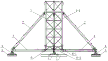
Fig. 1 is a schematic structural diagram of the present invention.
Fig. 2 is a top view of fig. 1.
Fig. 3 is a schematic view of the state of the linear beam and the intermediate connecting member during folding transportation.
Fig. 4 is a top view of fig. 3.
Fig. 5 is a schematic structural view of a linear beam.
Fig. 6 is a top view of fig. 5.
Fig. 7 is a schematic structural view of the stand.
Fig. 8 is a top view of fig. 7.
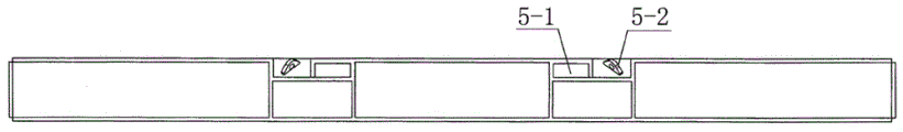
Fig. 9 is a schematic structural view of the leg.
Fig. 10 is a top view of fig. 9.
The sequence numbers in the figures illustrate: 1. 1-1 parts of tower bottom base sections and base section chord members; 2. obliquely supporting; 3. the hinge comprises a I-shaped beam 3-1, hinge bases I and 3-2 and a hinge base II; 4. 4-1 of a support, 4-2 of a lower bottom plate, 4-3 of an upper bottom plate, 4-4 of a vertical rib plate and 4-4 of a sealing plate; 5. 5-1 parts of supporting legs, 5-2 parts of positioning strips and 5-2 parts of pressing blocks; 6. the middle connecting piece 6-1, the upper connecting section 6-1-1, the connecting piece chord member 6-1-2, the connecting piece web member 6-2 and the diagonal cross; 7. a horizontally long stay bar; 8. horizontal short stay bar.
Detailed Description
The present invention will be further described with reference to the accompanying drawings:
as shown in figures 1-10, the utility model discloses an underframe system convenient to wind-powered electricity generation hoist and mount tower machine changes place includes tower bottom foundation festival (1) the same with tower body standard festival cross-section (when utilizing the utility model discloses when assembling wind-powered electricity generation hoist and mount tower machine, directly at the top overlap joint tower body standard festival of tower bottom foundation festival (1) can, easy operation, convenient to use, butt joint supports in the bottom of tower bottom foundation festival (1) below, by last continuous section (6-1) and the intermediate junction spare (6) that the diagonal angle cross (6-2) of lower part constitutes (intermediate junction spare (6) support through last continuous section (6-1) and connect tower bottom foundation festival (1), intermediate junction spare (6) form the big chassis of cross through four horizontal beams (3) articulated diagonal angle cross (6-2), articulate four ends at diagonal angle cross (6-2) respectively, The straight beam (3) which extends outwards (the straight beam (3) can be opened or closed quickly according to the needs of work or transportation, has the advantages of convenient transition, convenient assembly and disassembly, convenient transportation, simple operation and convenient use), four inclined supports (2) (the inclined supports (2) are respectively hinged between the top surfaces of the far ends of the four straight beams (3) and the upper parts of the base section chord rods (1-1) at the corresponding sides of the tower bottom base section (1) to form a right-angle large triangular support frame after being connected with the base section chord rods (1-1) and the straight beam (3), the load on the upper part of the tower crane is borne, the stress condition that the cross section of the traditional tower bottom base section is used as a main support is greatly improved, the stress is reasonable, the structure is simple, the dead weight is light, the economy and the practicability are realized, four sets of supports (4) which are respectively supported at the bottom of the far end of the straight beam (3) and the supporting legs (5) (the relatively reasonable base distance ensures that the stress when the supporting, correspondingly greatly reducing the requirement on the bearing capacity of the foundation, simultaneously saving the fixed tower body foundation, and being economical, practical and convenient for transition).
The utility model discloses in form two long vaulting poles of opposite vertex triangle-shaped (horizontal long vaulting pole (7) enclose into stable A-frame with two adjacent I-beam (3) after articulated two horizontal long vaulting poles (7) of support between the distal end of four I-beam (3), make I-beam (3) and diagonal angle cross (6-2) in corresponding short roof beam fix into a straight line, increase the lateral stability of I-beam (3), transmit horizontal direction's load to articulate two horizontal short vaulting poles (8) (increase A-frame's rigidity, and transmit horizontal direction load) between the middle part of every horizontal long vaulting pole (7) and two near-end ends of diagonal angle cross (6-2).
The utility model discloses in even section (6-1) is by four connecting piece chord members (6-1-1) and connecting piece web member (6-1-2) of vertical arrangement constitution, and the bottom of four connecting piece chord members (6-1-1) is fixed respectively on the top surface of four ends of diagonal angle cross (6-2) (four ends of diagonal angle cross (6-2) are as the support basis of even section (6-1) on.
The utility model discloses in hinge seat I (3-1) and hinge seat II (3-2) have been put to the both ends equipartition of a word roof beam (3), hinge seat I (3-1) is articulated mutually with diagonal cross (6-2), the axis of pinhole is vertical direction (the axis of pinhole is vertical direction, then the round pin axle is vertical direction, just so can guarantee that a word roof beam can carry out the horizontal rotation around the round pin axle, can open or fold according to the needs of work or transportation fast promptly), hinge seat II (3-2) is articulated mutually with bearing diagonal (2), the axis of pinhole is the horizontal direction (can follow the facade in the installation of bearing diagonal (2) and rotate).
The utility model discloses in support (4) is the four prismatic table structures (big end up down) that constitute by lower plate (4-1), upper plate (4-2), upright gusset (4-3) and shrouding (4-4) (prismatic table structure big end up is convenient for transmit upper portion load homodisperse to on landing leg (5) below, and lower plate (4-1) outwards extend shrouding (4-4) down outside along (be convenient for briquetting (5-2) compress tightly lower plate (4-1) fast).
The utility model discloses in landing leg (5) are cuboid box structure (be convenient for evenly pass to ground with the load), are provided with location strip (5-1) (be convenient for fix a position lower plate (4-1)) and briquetting (5-2) (be used for compressing tightly lower plate (4-1)) fast on landing leg (5).
The utility model discloses a concrete in service behavior as follows:
will the utility model discloses when transporting to the job site, carry out the spelling according to above-mentioned structure description earlier: firstly, arranging four sets of supports (4) and support legs (5) which are quickly positioned and pressed into a whole on corresponding positions on the ground; then, the intermediate connection (6) is placed on the ground in the centre; then horizontally rotating the two groups of folded linear beams (3) along the hinged ends of the diagonal crosses (6-2) to open, namely rotating the linear beams (3) and the corresponding short beams in the diagonal crosses (6-2) to be positioned on the same straight line, hoisting the middle connecting piece (6) and the four linear beams (3) to be positioned and installed right above the support (4); then, two long horizontal support rods (7) are hinged and supported between the far ends of the four straight beams (3) to form two opposite-vertex triangles, and two short horizontal support rods (8) are hinged between the middle part of each long horizontal support rod (7) and two near-end ends of the diagonal cross (6-2); then, butting the tower bottom base section (1) on the top of the upper connecting section (6-1) of the middle connecting piece (6); and finally, respectively hinging four inclined supports (2) between the top surfaces of the far ends of the four straight beams (3) and the upper parts of the base section chords (1-1) on the corresponding sides of the tower bottom base section (1). Thus, the utility model discloses just assembled fast and finish. Utilize the utility model discloses during equipment wind-powered electricity generation hoist and mount tower machine, only need at the tower bottom the direct overlap joint of top of foundation festival (1) with the tower body standard festival of cross-section can, easy operation, convenient to use.
After this stage of engineering construction finishes, when wind-powered electricity generation hoist and mount tower machine need carry out the circulation of changeing and use, demolish the tower body standard festival of upper portion with the cross-section earlier, will again the utility model discloses dismantle fast and transport: only need tear down four bearing diagonal (2) earlier promptly, demolish basic festival (1) at the bottom of the tower again, then tear down short vaulting pole of level (8), the long vaulting pole of level (7), will divide two sets of horizontal rotation of carrying on with four word roof beams (3) that diagonal angle cross (6-2) are articulated mutually and fold back whole transportation, unscrew briquetting (5-2), separation support (4) and landing leg (5), like this, the utility model discloses just, dismantle fast and finish, can transport and transition.
Claims (6)
1. The utility model provides an underframe system convenient to wind-powered electricity generation hoist and mount tower machine transition which characterized in that: the tower bottom foundation section comprises a tower bottom foundation section (1) with the same section as a tower body standard section, a middle connecting piece (6) which is supported below the tower bottom foundation section (1) in a butt joint mode and consists of an upper connecting section (6-1) and a diagonal cross (6-2) at the lower part, a linear beam (3) which is hinged to four ends of the diagonal cross (6-2) respectively and extends outwards, four inclined supports (2) which are hinged to the top surfaces of the far ends of the four linear beams (3) respectively and the upper parts of base section chord rods (1-1) at the corresponding side of the tower bottom foundation section (1), and four sets of supports (4) and four sets of supporting legs (5) which are supported at the bottom of the far ends of the linear beams (3) respectively.
2. The underframe system convenient for wind power hoisting tower crane to transition as claimed in claim 1, characterized in that: two long horizontal support rods (7) are hinged and supported between the far ends of the four straight beams (3) to form two opposite-vertex triangles, and two short horizontal support rods (8) are hinged between the middle part of each long horizontal support rod (7) and two near-end ends of the diagonal cross (6-2).
3. The underframe system convenient for wind power hoisting tower crane to transition as claimed in claim 1, characterized in that: the upper connecting section (6-1) is composed of four vertically arranged connecting piece chords (6-1-1) and connecting piece web members (6-1-2), and the bottoms of the four connecting piece chords (6-1-1) are respectively fixed on the top surfaces of four ends of the diagonal cross (6-2).
4. The underframe system convenient for wind power hoisting tower crane to transition as claimed in claim 1, characterized in that: the hinge base I (3-1) and the hinge base II (3-2) are uniformly arranged at two ends of the straight beam (3), the hinge base I (3-1) is hinged with the diagonal cross (6-2), the axis of the pin hole is in the vertical direction, the hinge base II (3-2) is hinged with the diagonal support (2), and the axis of the pin hole is in the horizontal direction.
5. The underframe system convenient for wind power hoisting tower crane to transition as claimed in claim 1, characterized in that: the support (4) is of a quadrangular frustum pyramid structure consisting of a lower bottom plate (4-1), an upper bottom plate (4-2), a vertical rib plate (4-3) and a sealing plate (4-4), and the lower bottom plate (4-1) extends outwards beyond the lower edge of the sealing plate (4-4).
6. The underframe system convenient for wind power hoisting tower crane to transition as claimed in claim 1, characterized in that: the supporting leg (5) is of a cuboid box-shaped structure, and a positioning strip (5-1) and a pressing block (5-2) are arranged on the supporting leg (5).
Priority Applications (1)
| Application Number | Priority Date | Filing Date | Title |
|---|---|---|---|
| CN201922099352.8U CN211110760U (en) | 2019-11-29 | 2019-11-29 | Underframe system convenient for wind power hoisting tower crane to transfer |
Applications Claiming Priority (1)
| Application Number | Priority Date | Filing Date | Title |
|---|---|---|---|
| CN201922099352.8U CN211110760U (en) | 2019-11-29 | 2019-11-29 | Underframe system convenient for wind power hoisting tower crane to transfer |
Publications (1)
| Publication Number | Publication Date |
|---|---|
| CN211110760U true CN211110760U (en) | 2020-07-28 |
Family
ID=71695734
Family Applications (1)
| Application Number | Title | Priority Date | Filing Date |
|---|---|---|---|
| CN201922099352.8U Active CN211110760U (en) | 2019-11-29 | 2019-11-29 | Underframe system convenient for wind power hoisting tower crane to transfer |
Country Status (1)
| Country | Link |
|---|---|
| CN (1) | CN211110760U (en) |
-
2019
- 2019-11-29 CN CN201922099352.8U patent/CN211110760U/en active Active
Similar Documents
| Publication | Publication Date | Title |
|---|---|---|
| CN202370253U (en) | Assembly type single-row vertical rod machining shed for building construction site | |
| CN205295918U (en) | Purlin piece is assembled to multipurpose standard | |
| CN103437283A (en) | Hanging basket truss fast to assemble | |
| CN102261043A (en) | Assembled steel pipe upright post system | |
| CN211110760U (en) | Underframe system convenient for wind power hoisting tower crane to transfer | |
| CN203034345U (en) | Coal transporting trestle of integral continuous steel truss | |
| CN202347867U (en) | Adjustable temporary support of high-altitude large-span truss | |
| CN217266925U (en) | Multipurpose standard H-shaped steel tower frame and connecting structure of cable hoisting system | |
| CN211470589U (en) | Tower crane for wind power hoisting convenient to transition | |
| CN202090612U (en) | Concrete distributing arm support and concrete pump truck | |
| CN205637164U (en) | Weak axle disconnect -type double T shape connection structure of I -shaped post who easily assembles | |
| CN214577533U (en) | Can realize cross chassis of wind-powered electricity generation tower machine of quick installation of diagonal brace | |
| CN202152442U (en) | Assembling type steel tube-vertical post system | |
| CN114704029A (en) | Steel-wood combined roof truss structure | |
| CN214570298U (en) | Wind power hoisting tower crane truss type chassis suitable for all-terrain weak earth pressure anti-inclination | |
| CN203247920U (en) | Frame structure used for 220kV or 500kV or 1000kV transformer station | |
| CN202864744U (en) | Space truss type tower crane | |
| CN218029366U (en) | Double-flat-arm electric holding rod arm support system capable of being folded into small caliber | |
| CN110745711B (en) | Tower crane convenient to transfer for wind power hoisting | |
| CN215561835U (en) | Quick expandable bridge based on X-shaped two-dimensional tensioning integral structure | |
| CN111550115B (en) | Reinforcing structure and reinforcing method for independent anchor column of railway T-beam bridge contact net | |
| CN211922250U (en) | Reinforced steel bridge | |
| CN214993177U (en) | Bearing structure is used in bent cap construction | |
| CN219528565U (en) | Hearth overhauling platform | |
| CN112551396A (en) | Wind power hoisting tower crane truss type chassis suitable for all-terrain weak earth pressure anti-inclination |
Legal Events
| Date | Code | Title | Description |
|---|---|---|---|
| GR01 | Patent grant | ||
| GR01 | Patent grant | ||
| TR01 | Transfer of patent right | ||
| TR01 | Transfer of patent right |
Effective date of registration: 20200818 Address after: High tech Zone of Henan city in Zhengzhou province 450001 pagoda Street No. 8 Co-patentee after: HUADIAN ZHENGZHOU MECHANICAL DESIGN INSTITUTE Co.,Ltd. Patentee after: KERUN ELECTRO-MECHANICAL ENGINEERING Co.,Ltd. Address before: High tech Zone of Henan city in Zhengzhou province 450001 pagoda Street No. 8 Patentee before: KERUN ELECTRO-MECHANICAL ENGINEERING Co.,Ltd. |