CN211102401U - Welding jig frame for spray pipe nozzle of dust remover - Google Patents
Welding jig frame for spray pipe nozzle of dust remover Download PDFInfo
- Publication number
- CN211102401U CN211102401U CN201921958750.4U CN201921958750U CN211102401U CN 211102401 U CN211102401 U CN 211102401U CN 201921958750 U CN201921958750 U CN 201921958750U CN 211102401 U CN211102401 U CN 211102401U
- Authority
- CN
- China
- Prior art keywords
- nozzle
- welding
- spray pipe
- spray tube
- dust remover
- Prior art date
- Legal status (The legal status is an assumption and is not a legal conclusion. Google has not performed a legal analysis and makes no representation as to the accuracy of the status listed.)
- Active
Links
Images


Abstract
The utility model relates to a dust remover spray tube nozzle welding bed-jig has the welding platen, is provided with a dovetail groove along length direction on the welding platen, sliding connection has a plurality of nozzle positioning baffle in the dovetail groove, one side of welding platen is equipped with L shape spray tube shelf, and the outside is arranged in to the curb plate of L shape spray tube shelf, and the diaphragm of L shape spray tube shelf is facing to the lateral wall of welding platen and reciprocates along the lateral wall, and lift jacking device is still equipped with to the bottom of L shape spray tube shelf, and L shape spray tube shelf reciprocates under lift jacking device's effect and adjusts, the utility model discloses welding bed-jig structural design is simple, but uses and adjusts all very conveniently, easily operates, and is very obvious to machining efficiency's promotion effect.
Description
Technical Field
The utility model belongs to the technical field of machine tooling equipment technique and specifically relates to a dust remover spray tube nozzle welding bed-jig.
Background
In the production process of large-scale dust remover, weld on the dust removal spray tube of blowing and be equipped with a plurality of little nozzles and blow, the nozzle all is the circular steel tube usually, with the circular steel tube welding on the spray tube lateral wall, traditional way all adopts fixed manual welding that makes progress of fixture equipment, but this kind of way leads to the crooked condition of welding to appear in the nozzle pipe very easily, influence product quality, and also relatively consume time at the in-process of confirming the nozzle interval, every nozzle of welding just need confirm interval repetitive operation, waste time and energy, welding machining efficiency is low.
Disclosure of Invention
The utility model aims at providing a dust remover spray tube nozzle welding bed-jig to above-mentioned condition, this welding bed-jig structural design is simple, but it is all very convenient to use and adjust, and easily operation is very obvious to machining efficiency's promotion effect.
The utility model discloses a dust remover spray tube nozzle welding bed-jig has the welding platen, is provided with a dovetail groove along length direction on the welding platen, sliding connection has a plurality of nozzle positioning baffle in the dovetail groove, one side of welding platen is equipped with L shape spray tube shelf, and the curb plate of L shape spray tube shelf is arranged in the outside, and the diaphragm of L shape spray tube shelf faces the lateral wall of welding platen and reciprocates along the lateral wall, and the bottom of L shape spray tube shelf still is equipped with lift jacking device, and L shape spray tube shelf reciprocates under the effect of lift jacking device and adjusts.
Further, in the utility model discloses in nozzle location baffle is L shape angle steel piece, and the bottom of L shape angle steel piece is equipped with trapezoidal slider, trapezoidal slider slides in the dovetail groove that corresponds.
Furthermore, in the utility model discloses in the one end of L shape spray tube shelf still is equipped with spray tube end baffle.
Further, in the utility model discloses in lift jacking device adopts the pneumatic cylinder to carry out the jacking action.
Further, the utility model discloses in along dovetail groove still is equipped with the scale in its upper portion edge, and this scale is used for nozzle positioning baffle's regulation location.
The utility model discloses a welding bed-jig all utilizes some current corner material preparations in the workshop to form, and preparation low cost uses more nimble convenience, and the most important is the welding adjustment that can adapt to different nozzle spray tube sizes in the certain limit, has greatly promoted the welding quality of welding machining efficiency and product.
Drawings
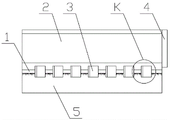
Fig. 1 is a schematic view of the top view structure of the present invention;
fig. 2 is a schematic side view of the structure of the present invention;
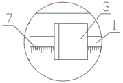
FIG. 3 is an enlarged view of the structure at K in FIG. 1;
FIG. 4 is a schematic side view of the utility model in use;
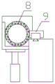
fig. 5 is a schematic view of a nozzle of the present invention.
In the figure, 1-trapezoidal groove, 2-L-shaped spray pipe shelf, 3-nozzle positioning baffle, 4-spray pipe end baffle, 5-welding platen, 6-trapezoidal slide block, 7-graduated scale, 8-spray pipe, 9-nozzle, 10-hydraulic cylinder.
Detailed Description
Referring to fig. 1-5, the utility model relates to a dust remover spray tube nozzle welding bed-jig has welding platen 5, is provided with a dovetail groove 1 along length direction on the welding platen, sliding connection has a plurality of nozzle positioning baffle 3 in the dovetail groove, one side of welding platen is equipped with L shape spray tube shelf 2, the curb plate of L shape spray tube shelf is arranged in the outside, the diaphragm of L shape spray tube shelf is facing to the lateral wall of welding platen and is reciprocated along the lateral wall, lift jacking device is still equipped with to the bottom of L shape spray tube shelf, L shape spray tube shelf reciprocates under the effect of lift jacking device and adjusts.
Further, in this embodiment, the nozzle positioning baffle is an L-shaped angle steel block, and a trapezoidal sliding block 6 is arranged at the bottom of the L-shaped angle steel block and slides in a corresponding trapezoidal groove.
Further, in this embodiment, one end of the L-shaped spout shelf is also provided with a spout end baffle 4.
Further, in this embodiment, the lifting and jacking device adopts the hydraulic cylinder 10 to perform jacking operation.
Further, in the embodiment, a graduated scale 7 is further arranged along the upper edge of the trapezoidal groove, and the graduated scale is used for adjusting and positioning the nozzle positioning baffle.
The utility model discloses when carrying out welding operation, arrange the spray tube in L shape spray tube shelves earlier, and support the one end of spray tube on spray tube end baffle, because before the welding, corresponding welding hole has just been seted up on the spray tube, consequently only need place the welding hole side direction this moment, then each nozzle positioning baffle in the removal dovetail groove aligns to the welding hole department on the spray tube, after aligning, place the nozzle stub pipe on nozzle positioning baffle in every welding hole department again, carry out whole welding completions after the first spot welding location of last one more.
In the process, the nozzles are positioned and aligned by adopting the uniform and level nozzle positioning baffle plates, so that the welded nozzles have relatively good quality and are very flat and attractive.
In actual operation process, operating personnel can adjust L shape spray tube shelf's height through lift jacking device according to the spray tube nozzle size of difference, comes real-time adjustment interval through the removal of nozzle positioning baffle in the dovetail groove simultaneously, and it is all very convenient to adjust.
Claims (5)
1. A nozzle welding jig frame of a dust remover spray pipe is characterized by comprising a welding bedplate, wherein a trapezoidal groove is formed in the welding bedplate along the length direction, a plurality of nozzle positioning baffle plates are connected in the trapezoidal groove in a sliding mode, an L-shaped spray pipe shelf is arranged on one side of the welding bedplate, a side plate of the L-shaped spray pipe shelf is arranged on the outer side, a transverse plate of the L-shaped spray pipe shelf faces the side wall of the welding bedplate and moves up and down along the side wall, a lifting and jacking device is further arranged at the bottom of the L-shaped spray pipe shelf, and the L-shaped spray pipe shelf moves up and down under the action of the lifting and.
2. The welding jig for the nozzle of the dust remover nozzle pipe as claimed in claim 1, wherein the nozzle positioning baffle is an L-shaped angle steel block, and a trapezoidal sliding block is arranged at the bottom of the L-shaped angle steel block and slides in a corresponding trapezoidal groove.
3. The welding jig frame for the spray pipe nozzle of the dust remover as claimed in claim 1, wherein one end of the L-shaped spray pipe shelf is further provided with a spray pipe end baffle.
4. The nozzle welding jig of the dust remover nozzle pipe according to claim 1, wherein: and the lifting jacking device adopts a hydraulic cylinder to perform jacking action.
5. The nozzle welding jig of the dust remover nozzle pipe according to claim 1, wherein: and a graduated scale is further arranged at the upper edge of the trapezoid groove and used for adjusting and positioning the nozzle positioning baffle.
Priority Applications (1)
| Application Number | Priority Date | Filing Date | Title |
|---|---|---|---|
| CN201921958750.4U CN211102401U (en) | 2019-11-14 | 2019-11-14 | Welding jig frame for spray pipe nozzle of dust remover |
Applications Claiming Priority (1)
| Application Number | Priority Date | Filing Date | Title |
|---|---|---|---|
| CN201921958750.4U CN211102401U (en) | 2019-11-14 | 2019-11-14 | Welding jig frame for spray pipe nozzle of dust remover |
Publications (1)
| Publication Number | Publication Date |
|---|---|
| CN211102401U true CN211102401U (en) | 2020-07-28 |
Family
ID=71724265
Family Applications (1)
| Application Number | Title | Priority Date | Filing Date |
|---|---|---|---|
| CN201921958750.4U Active CN211102401U (en) | 2019-11-14 | 2019-11-14 | Welding jig frame for spray pipe nozzle of dust remover |
Country Status (1)
| Country | Link |
|---|---|
| CN (1) | CN211102401U (en) |
-
2019
- 2019-11-14 CN CN201921958750.4U patent/CN211102401U/en active Active
Similar Documents
| Publication | Publication Date | Title |
|---|---|---|
| CN103151550A (en) | Device for assembling laminated stacks | |
| CN104525813A (en) | Double-station pre-pressing forming hydraulic machine | |
| CN107695736A (en) | Milling groove positioning device | |
| CN203676004U (en) | Four-station rotating disc type tea pressing machine | |
| CN211102401U (en) | Welding jig frame for spray pipe nozzle of dust remover | |
| CN207431333U (en) | Clamping workpiece blanking units | |
| CN210413167U (en) | Multi-station high-efficiency welding device | |
| CN207239570U (en) | A kind of pneumatic localization machine of welding tooling | |
| CN209579398U (en) | A kind of adjustable multistation spacing pressing mounting tool | |
| CN215034932U (en) | Adjustable positioning welding tool for stator core punching sheet of traction machine motor | |
| CN108687237A (en) | A kind of high-precision flange hardware dies | |
| CN202984943U (en) | Upright H-shaped steel clamping device | |
| CN208292229U (en) | Automatic blanking device | |
| CN210060298U (en) | Die-casting box sizing device | |
| CN204209292U (en) | A kind of building aluminum alloy pattern plate welding equipment | |
| CN208290592U (en) | A kind of fiber can grinds edge equipment automatically | |
| CN208787838U (en) | Fuel tank cap puppet's mounted welder | |
| CN208214901U (en) | One kind being used for coupler cavity punching positioning tool | |
| CN208513423U (en) | A kind of easily demoulding die punching machine | |
| CN214978968U (en) | Smelting workpiece welding tool | |
| CN201625875U (en) | Eccentric rapid clamping tool | |
| CN206276979U (en) | Chassis feeds steel billet cutter sweep | |
| CN108637101A (en) | A kind of drilling rod protective case production technology | |
| CN204817568U (en) | Workstation is rectified to fixed base crane end beam | |
| CN211360394U (en) | Auto-parts punching press automatic production line |
Legal Events
| Date | Code | Title | Description |
|---|---|---|---|
| GR01 | Patent grant | ||
| GR01 | Patent grant |