CN211101192U - Automatic platen mechanism and automatic loading and unloading indexing punching device - Google Patents

Automatic platen mechanism and automatic loading and unloading indexing punching device Download PDF

Info

Publication number
CN211101192U
CN211101192U CN201921216332.8U CN201921216332U CN211101192U CN 211101192 U CN211101192 U CN 211101192U CN 201921216332 U CN201921216332 U CN 201921216332U CN 211101192 U CN211101192 U CN 211101192U
Authority
CN
China
Prior art keywords
piece
automatic
punching
sliding
pressing plate
Prior art date
Legal status (The legal status is an assumption and is not a legal conclusion. Google has not performed a legal analysis and makes no representation as to the accuracy of the status listed.)
Active
Application number
CN201921216332.8U
Other languages
Chinese (zh)
Inventor
杨向东
樊金标
梁志昌
尹定红
蒋科
刘烨
胡泳涛
赵波
卢文德
龚继林
张燕航
刘洁
文春鱼
曾德发
Current Assignee (The listed assignees may be inaccurate. Google has not performed a legal analysis and makes no representation or warranty as to the accuracy of the list.)
Tangjia Hardware Products Jiangsu Co ltd
Original Assignee
Guangdong Jingubang Pipe Pile Foundation Co ltd
Guangdong Yima Group Co ltd
Guangzhou Yima Casting & Forging Industry Co ltd
Jiangsu Yima Casting & Forging Co ltd
Jurong Yima Hardware Product Co ltd
Jurong Zhongsheng Belt Technology Co ltd
Liaoning Yima Hardware Co ltd
Tianjin Yima Metal Products Co ltd
Wuzhou Yima Hardware Products Co ltd
Zhongshan Stainless Steel Technology Co ltd
Zhongshan Zhongsheng Metal Plate And Strip Technology Co ltd
Zhongshan Liuliuliu Intelligent Equipment Co ltd
Priority date (The priority date is an assumption and is not a legal conclusion. Google has not performed a legal analysis and makes no representation as to the accuracy of the date listed.)
Filing date
Publication date
Application filed by Guangdong Jingubang Pipe Pile Foundation Co ltd, Guangdong Yima Group Co ltd, Guangzhou Yima Casting & Forging Industry Co ltd, Jiangsu Yima Casting & Forging Co ltd, Jurong Yima Hardware Product Co ltd, Jurong Zhongsheng Belt Technology Co ltd, Liaoning Yima Hardware Co ltd, Tianjin Yima Metal Products Co ltd, Wuzhou Yima Hardware Products Co ltd, Zhongshan Stainless Steel Technology Co ltd, Zhongshan Zhongsheng Metal Plate And Strip Technology Co ltd, Zhongshan Liuliuliu Intelligent Equipment Co ltd filed Critical Guangdong Jingubang Pipe Pile Foundation Co ltd
Priority to CN201921216332.8U priority Critical patent/CN211101192U/en
Application granted granted Critical
Publication of CN211101192U publication Critical patent/CN211101192U/en
Active legal-status Critical Current
Anticipated expiration legal-status Critical

Links

Images

Landscapes

  • Perforating, Stamping-Out Or Severing By Means Other Than Cutting (AREA)

Abstract

本实用新型涉及自动压板机构及自动上下料分度冲孔装置,该自动压板机构包括底座、第一驱动件和滑动件,第一驱动件包括连接在底座上的第一主体以及可从第一主体沿水平方向伸缩的第一推动件,滑动件与第一推动件连接;自动压板机构还包括第二驱动件、升降件、悬臂件以及压板件,升降件与滑动件连接,第二驱动件驱动所述升降件在滑动件上沿竖直方向移动;悬臂件第一端与升降件连接,悬臂件第二端下方与压板件连接;当第一驱动件驱动滑动件移动时,悬臂件第二端能够伸出到底座的外侧。该自动上下料分度冲孔装置包括冲孔工作台、输送机构以及自动压板机构。本实用新型能够实现自动压板和自动上下料冲孔,生产效率高。

Figure 201921216332

The utility model relates to an automatic platen pressing mechanism and an automatic loading and unloading indexing punching device. The automatic platen pressing mechanism comprises a base, a first driving part and a sliding part. The first driving part comprises a first main body connected on the base and a The main body is stretched and retracted in the horizontal direction, and the sliding piece is connected with the first pushing piece; the automatic platen pressing mechanism also includes a second driving piece, a lifting piece, a cantilever piece and a pressing board piece, the lifting piece is connected with the sliding piece, and the second driving piece The lifting member is driven to move in the vertical direction on the sliding member; the first end of the cantilever member is connected with the lifting member, and the lower part of the second end of the cantilever member is connected with the pressing plate member; when the first driving member drives the sliding member to move, the cantilever member first The two ends can protrude to the outside of the base. The automatic loading and unloading indexing punching device includes a punching table, a conveying mechanism and an automatic pressing plate mechanism. The utility model can realize automatic plate pressing and automatic loading and unloading punching, and has high production efficiency.

Figure 201921216332

Description

自动压板机构及自动上下料分度冲孔装置Automatic platen mechanism and automatic loading and unloading indexing punching device

技术领域technical field

本实用新型涉及自动化设备技术领域,具体涉及自动压板机构及自动上下料分度冲孔装置。The utility model relates to the technical field of automation equipment, in particular to an automatic pressing plate mechanism and an automatic loading and unloading indexing punching device.

背景技术Background technique

法兰端板是管桩的重要零部件,主要用于管桩的连接。如图9所示,端板工件600上设有攻丝孔610和沉头孔620,在攻丝孔610和沉头孔620 之间设有连接孔630。现有的冲孔装置对端板进行冲孔加工以形成连接孔 630,可以采用单孔冲孔,单孔冲孔加工是一个一个孔进行的,通过移动或转动端板进行加工,获得多个孔。为避免端板移动,在单孔冲孔时通常需要对端板法兰压紧固定。现有的单孔冲孔装置无法自动压板固定,也无法自动上下料,人力劳动强度大,生产效率低,生产成本高。Flange end plate is an important part of pipe pile, mainly used for the connection of pipe pile. As shown in FIG. 9 , the end plate workpiece 600 is provided with a tapping hole 610 and a countersunk hole 620 , and a connecting hole 630 is provided between the tapping hole 610 and the countersunk hole 620 . The existing punching device punches the end plate to form the connecting hole 630. Single-hole punching can be used. The single-hole punching process is carried out one hole at a time. By moving or rotating the end plate for processing, multiple hole. In order to avoid the movement of the end plate, it is usually necessary to press and fix the flange of the end plate when punching a single hole. The existing single-hole punching device cannot be automatically fixed by a platen, nor can it be automatically loaded and unloaded, the labor intensity is high, the production efficiency is low, and the production cost is high.

实用新型内容Utility model content

针对现有技术的不足,本实用新型的第一目的是提供一种能够自动将端板压紧在冲孔工作台上的自动压板机构。In view of the deficiencies of the prior art, the first objective of the present invention is to provide an automatic platen pressing mechanism capable of automatically pressing the end plate on the punching table.

本实用新型的第二目的是提供一种能够自动输料进行冲孔、节省人力、提高生产效率、节约成本的自动上下料分度冲孔装置。The second purpose of the utility model is to provide an automatic loading and unloading indexing punching device capable of automatically feeding materials for punching, saving manpower, improving production efficiency and saving costs.

为实现本实用新型的第一目的,本实用新型提供了一种自动压板机构,包括底座、第一驱动件和滑动件,第一驱动件包括连接在底座上的第一主体以及可从第一主体沿水平方向伸缩的第一推动件,滑动件与第一推动件连接;自动压板机构还包括第二驱动件、升降件、悬臂件以及压板件,升降件与滑动件连接,第二驱动件驱动所述升降件在滑动件上沿竖直方向移动;悬臂件第一端与升降件连接,悬臂件第二端下方与压板件连接;当第一驱动件驱动滑动件移动时,悬臂件第二端能够伸出到底座的外侧。In order to achieve the first object of the present utility model, the present utility model provides an automatic pressing plate mechanism, which includes a base, a first driving member and a sliding member, and the first driving member includes a first main body connected to the base and a The main body is stretched and retracted in the horizontal direction, and the sliding part is connected with the first pushing part; the automatic platen pressing mechanism also includes a second driving part, a lifting part, a cantilever part and a pressing plate part, the lifting part is connected with the sliding part, and the second driving part The lifting member is driven to move in the vertical direction on the sliding member; the first end of the cantilever member is connected with the lifting member, and the lower part of the second end of the cantilever member is connected with the pressing plate member; when the first driving member drives the sliding member to move, the cantilever member first The two ends can protrude to the outside of the base.

进一步的技术方案是,压板件设有缺口。A further technical solution is that the pressing plate member is provided with a notch.

进一步的技术方案是,自动压板机构还包括导向件;导向件连接在底座上,导向件的延伸方向与第一推动件的伸缩方向平行;滑动件包括相互连接的滑块和滑座,滑块与导向件可移动地配合;第二驱动件包括第二主体以及可从第二主体沿竖直方向伸缩的第二推动件,第二主体与滑座连接,第二推动件与升降件连接。A further technical solution is that the automatic platen pressing mechanism further includes a guide; the guide is connected to the base, and the extension direction of the guide is parallel to the telescopic direction of the first pusher; It is movably matched with the guide piece; the second driving piece includes a second main body and a second pushing piece that can be extended and retracted from the second main body in the vertical direction, the second main body is connected with the sliding seat, and the second pushing piece is connected with the lifting piece.

进一步的技术方案是,自动压板机构还包括定位件,定位件连接压板件和悬臂件;自动压板机构还包括第三驱动件以及顶紧件,第三驱动件驱动顶紧件向定位件移动并顶紧定位件。A further technical solution is that the automatic platen pressing mechanism further includes a positioning member, which connects the pressing plate member and the cantilever member; the automatic platen pressing mechanism further includes a third driving member and a pressing member, and the third driving member drives the pressing member to move toward the positioning member and Tighten the positioning piece.

进一步的技术方案是,第一驱动件、第二驱动件和第三驱动件分别为气缸或油缸。A further technical solution is that the first driving member, the second driving member and the third driving member are cylinders or oil cylinders, respectively.

进一步的技术方案是,自动压板机构还包括位于底座下方的托架和位于底座一端的安装块。A further technical solution is that the automatic plate-pressing mechanism further includes a bracket located below the base and a mounting block located at one end of the base.

为实现本实用新型的第二目的,本实用新型提供了一种自动上下料分度冲孔装置,包括冲孔工作台、输送机构和自动压板机构,输送机构的末端与冲孔工作台的端部邻接,自动压板机构包括底座、第一驱动件和滑动件,底座设置在冲孔工作台一侧,第一驱动件包括连接在底座上的第一主体以及可从第一主体沿水平方向伸缩的第一推动件,滑动件与第一推动件连接;自动压板机构还包括第二驱动件、升降件、悬臂件以及压板件,升降件与滑动件连接,第二驱动件驱动升降件在滑动件上沿竖直方向移动;悬臂件第一端与升降件连接,悬臂件第二端下方与压板件连接;当第一驱动件驱动滑动件移动时,悬臂件第二端能够伸出到冲孔工作台的上方。In order to achieve the second purpose of the present utility model, the present utility model provides an automatic loading and unloading indexing punching device, which includes a punching table, a conveying mechanism and an automatic platen mechanism, the end of the conveying mechanism and the end of the punching table. The automatic pressing plate mechanism includes a base, a first driving member and a sliding member, the base is arranged on one side of the punching table, and the first driving member includes a first main body connected to the base and can be extended and retracted from the first main body in the horizontal direction. The first pusher is connected with the first pusher; the automatic platen mechanism also includes a second drive, a lifter, a cantilever and a platen, the lifter is connected with the slider, and the second drive drives the lifter to slide The upper part of the cantilever part moves in the vertical direction; the first end of the cantilever part is connected with the lifting part, and the lower part of the second end of the cantilever part is connected with the pressing plate part; when the first driving part drives the sliding part to move, the second end of the cantilever part can extend to the punching part. above the hole table.

进一步的技术方案是,压板件设有缺口。A further technical solution is that the pressing plate member is provided with a notch.

进一步的技术方案是,自动压板机构还包括导向件;导向件连接在底座上,导向件的延伸方向与第一推动件的伸缩方向平行;滑动件包括相互连接的滑块和滑座,滑块与导向件可移动地配合;第二驱动件包括第二主体以及可从第二主体沿竖直方向伸缩的第二推动件,第二主体与滑座连接,第二推动件与升降件连接。A further technical solution is that the automatic platen pressing mechanism further includes a guide; the guide is connected to the base, and the extension direction of the guide is parallel to the telescopic direction of the first pusher; It is movably matched with the guide piece; the second driving piece includes a second main body and a second pushing piece that can be extended and retracted from the second main body in the vertical direction, the second main body is connected with the sliding seat, and the second pushing piece is connected with the lifting piece.

进一步的技术方案是,自动压板机构还包括定位件,定位件连接压板件和悬臂件;自动压板机构还包括第三驱动件以及顶紧件,第三驱动件可驱动顶紧件向定位件移动并顶紧定位件。A further technical solution is that the automatic platen pressing mechanism further includes a positioning member, and the positioning member connects the pressing plate member and the cantilever member; the automatic platen pressing mechanism further includes a third driving member and a pressing member, and the third driving member can drive the pressing member to move toward the positioning member. And tighten the positioning piece.

进一步的技术方案是,第一驱动件、第二驱动件和第三驱动件分别为气缸或油缸。A further technical solution is that the first driving member, the second driving member and the third driving member are cylinders or oil cylinders, respectively.

进一步的技术方案是,自动压板机构还包括位于底座下方的托架和位于底座一端的安装块;底座与安装块连接到冲孔工作台。A further technical solution is that the automatic platen pressing mechanism further comprises a bracket located below the base and a mounting block located at one end of the base; the base and the mounting block are connected to the punching table.

进一步的技术方案是,冲孔工作台包括支撑台和分度转动机构,支撑台用于支撑工件,分度转动机构带动工件转动;自动上下料分度冲孔装置还包括冲孔机,冲孔机包括单个冲孔头,冲孔头位于支撑台的上方,冲孔头可上下移动。A further technical solution is that the punching table includes a support table and an indexing and rotating mechanism, the support table is used to support the workpiece, and the indexing and rotating mechanism drives the workpiece to rotate; the automatic loading and unloading indexing punching device also includes a punching machine, which is used for punching. The machine includes a single punching head, the punching head is located above the support table, and the punching head can move up and down.

进一步的技术方案是,分度转动机构包括设在蜗轮以及由电机驱动的蜗杆,所述蜗杆与所述蜗轮配合。A further technical solution is that the indexing rotation mechanism includes a worm gear provided on the worm wheel and a worm screw driven by a motor, and the worm screw is matched with the worm wheel.

进一步的技术方案是,输送机构包括进料辊道和出料辊道,进料辊道和出料辊道分别连接冲孔工作台的两端。A further technical solution is that the conveying mechanism includes a feeding roller table and a discharging roller table, and the feeding roller table and the discharging roller table are respectively connected to both ends of the punching table.

与现有技术相比,本实用新型能够取得以下有益效果:Compared with the prior art, the utility model can achieve the following beneficial effects:

1.本实用新型提供了一种自动压板机构,该自动压板机构适用于自动上下料分度冲孔装置,该自动压板机构通过第一驱动件驱动滑动件水平移动、第二驱动件驱动升降件垂直移动,使得压板件能够伸到冲孔工作台的上方,并且下压压紧工件,在对工件进行单孔冲孔时,能够有效避免工件移动。本实用新型的自动压板机构还具有结构简单、稳定性高的优点。1. The utility model provides an automatic platen pressing mechanism, which is suitable for an automatic loading and unloading indexing and punching device. The automatic platen pressing mechanism drives the sliding member to move horizontally through the first driving member, and the second driving member drives the lifting member. The vertical movement enables the pressing plate to extend above the punching table and press down the workpiece, which can effectively prevent the workpiece from moving when single-hole punching is performed on the workpiece. The automatic plate pressing mechanism of the utility model also has the advantages of simple structure and high stability.

2.本实用新型的自动上下料分度冲孔装置包括输送机构和自动压板机构,通过进料辊道向冲孔工作台输送待冲孔工件,自动压板机构压紧工件进行单孔冲孔,单孔冲孔完成后,自动压板机构解除对工件的压紧,分度转动机构带动工件转动特定角度,自动压板机构再压紧工件进行下一个孔的冲孔,直至完成端板所有孔的冲孔。端板冲孔完成后,工件离开冲孔工作台,进入出料辊道。此时,下一个待冲孔工件可以进入冲孔工作台,进行下一个工件的冲孔加工。如此重复,能够实现工件的连续上料、冲孔和下料,降低了人力劳动强度,提高了生产效率,降低了生产成本。2. The automatic loading and unloading indexing punching device of the present utility model includes a conveying mechanism and an automatic pressing plate mechanism. The workpiece to be punched is transported to the punching table through the feeding roller, and the automatic pressing plate mechanism presses the workpiece to perform single-hole punching. After the single-hole punching is completed, the automatic pressing plate mechanism releases the pressing of the workpiece, the indexing and rotating mechanism drives the workpiece to rotate at a specific angle, and the automatic pressing plate mechanism presses the workpiece again to punch the next hole until the punching of all the holes in the end plate is completed. hole. After the end plate punching is completed, the workpiece leaves the punching table and enters the discharge roller table. At this time, the next workpiece to be punched can enter the punching table for punching processing of the next workpiece. Such repetition can realize the continuous feeding, punching and unloading of the workpiece, which reduces the labor intensity, improves the production efficiency, and reduces the production cost.

附图说明Description of drawings

图1是本实用新型自动压板机构实施例的立体结构示意图。FIG. 1 is a schematic three-dimensional structure diagram of an embodiment of an automatic platen pressing mechanism of the present invention.

图2是本实用新型自动压板机构实施例的主视图。FIG. 2 is a front view of the embodiment of the automatic platen pressing mechanism of the present invention.

图3是本实用新型自动压板机构实施例的俯视图。FIG. 3 is a top view of an embodiment of the automatic platen pressing mechanism of the present invention.

图4是本实用新型自动推板机构实施例的左视图。Fig. 4 is the left side view of the embodiment of the automatic push plate mechanism of the present invention.
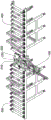
图5是本实用新型自动上下料分度冲孔装置实施例的立体结构示意图。Figure 5 is a schematic three-dimensional structure diagram of an embodiment of the automatic loading and unloading indexing punching device of the present invention.

图6是本实用新型自动上下料分度冲孔装置实施例(包括冲孔机)的主视图。6 is a front view of an embodiment of the automatic loading and unloading indexing punching device of the present invention (including a punching machine).

图7是本实用新型自动上下料分度冲孔装置实施例的俯视图。7 is a top view of an embodiment of the automatic loading and unloading indexing punching device of the present invention.

图8是本实用新型自动上下料分度冲孔装置实施例的左视图。Fig. 8 is the left side view of the embodiment of the automatic loading and unloading indexing punching device of the present invention.

图9是本实用新型自动上下料分度冲孔装置实施例待冲孔工件(a)和冲孔后工件(b)的结构示意图。9 is a schematic structural diagram of the workpiece to be punched (a) and the workpiece after punching (b) according to the embodiment of the automatic loading and unloading indexing punching device of the present invention.

具体实施方式Detailed ways

自动压板机构实施例Example of automatic platen mechanism

如图1至4所示,本实施例的自动压板机构100包括底座110、第一驱动件120、滑动件130、第二驱动件140、升降件150、悬臂件160、压板件 170、定位件180和导向件190。As shown in FIGS. 1 to 4 , the automatic platen pressing mechanism 100 of this embodiment includes a base 110 , a first driving member 120 , a sliding member 130 , a second driving member 140 , a lifting member 150 , a cantilever member 160 , a pressing plate member 170 , and a positioning member 180 and guide 190.

第一驱动件120包括连接在底座110上的第一主体121以及可从第一主体121沿水平方向伸缩的第一推动件122。在本实施例中,第一驱动件 120为气缸,第一主体121为气缸缸体,第一推动件122为推杆。The first driving member 120 includes a first main body 121 connected to the base 110 and a first pushing member 122 that can extend and contract from the first main body 121 in a horizontal direction. In this embodiment, the first driving member 120 is a cylinder, the first main body 121 is a cylinder block, and the first pushing member 122 is a push rod.

滑动件130包括滑座131和滑块132。第一推动件122的末端与滑座 131连接,因此第一驱动件120能够驱动滑动件130水平移动。滑块132连接在滑座131的下方。The sliding member 130 includes a sliding seat 131 and a sliding block 132 . The end of the first pushing member 122 is connected with the sliding seat 131, so the first driving member 120 can drive the sliding member 130 to move horizontally. The sliding block 132 is connected below the sliding seat 131 .

第二驱动件140包括第二主体141和可从第二主体141沿竖直方向伸缩的第二推动件142,第二主体141固定在滑座131下方,第二推动件142 穿过滑座131且第二推动件的末端连接升降件150,因此第二驱动件140能够驱动升降件150上下移动。在本实施例中,第二驱动件181为气缸。The second driving member 140 includes a second main body 141 and a second pushing member 142 that can be extended and retracted from the second main body 141 in the vertical direction. The second main body 141 is fixed under the sliding seat 131 , and the second pushing member 142 passes through the sliding seat 131 And the end of the second pushing member is connected to the lifting member 150 , so the second driving member 140 can drive the lifting member 150 to move up and down. In this embodiment, the second driving member 181 is an air cylinder.

升降件150与悬臂件160的第一端固定连接,悬臂件160的第二端通过定位件180连接压板件170。当第一驱动件120驱动滑动件130移动时,悬臂件160第二端能够伸出到底座110的外侧,即悬臂件160第二端能够离开底座110所在的区域,能够压住底座110外侧的待冲孔的工件600。压板件170设有缺口171,缺口171的设置是为了便于冲孔。The lifting member 150 is fixedly connected to the first end of the cantilever member 160 , and the second end of the cantilever member 160 is connected to the pressing plate member 170 through the positioning member 180 . When the first driving member 120 drives the sliding member 130 to move, the second end of the cantilever member 160 can protrude to the outside of the base 110 , that is, the second end of the cantilever member 160 can be away from the area where the base 110 is located, and can press the outer side of the base 110 . Workpiece 600 to be punched. The pressing plate member 170 is provided with a notch 171 , and the notch 171 is provided to facilitate punching.

导向件190设置在底座110上,在本实施例中,导向件190为两个导轨,导轨的延伸方向与第一推动件122的伸缩方向平行。滑块132为4个,每两个滑块132与一个导轨配合,使得滑动件130的水平移动更加稳定。The guide member 190 is disposed on the base 110 . In this embodiment, the guide member 190 is two guide rails, and the extension direction of the guide rails is parallel to the extension direction of the first push member 122 . There are four sliding blocks 132 , and every two sliding blocks 132 is matched with a guide rail, so that the horizontal movement of the sliding member 130 is more stable.

自动压板机构100还包括第三驱动件181以及顶紧件182,第三驱动件 181能够驱动顶紧件182向定位件180移动并顶紧定位件180,避免定位件移动或转动。在本实施例中,第三驱动件181为气缸。The automatic platen pressing mechanism 100 further includes a third driving member 181 and a pressing member 182. The third driving member 181 can drive the pressing member 182 to move toward the positioning member 180 and press the positioning member 180 to prevent the positioning member from moving or rotating. In this embodiment, the third driving member 181 is an air cylinder.

自动压板机构100还包括位于底座110下方的托架111和位于底座一端的安装块112。托架111和安装块112用于将自动压板机构100安装到其他固定机构中。The automatic platen pressing mechanism 100 further includes a bracket 111 located below the base 110 and a mounting block 112 located at one end of the base. The bracket 111 and the mounting block 112 are used to mount the automatic platen mechanism 100 into other fixing mechanisms.

自动上下料分度冲孔装置实施例Example of automatic loading and unloading indexing punching device

如图5至8所示,本实施例的自动上下料分度冲孔装置包括冲孔工作台200、输送机构、上述自动压板机构实施例中的自动压板机构100以及冲孔机300。自动压板机构100设置在冲孔工作台200的第一侧,冲孔机300 设置在冲孔工作台200的第二侧。其中自动压板机构100的底座110通过托架111和安装块112安装到冲孔工作台200上,第一驱动件120的第二推动件122的伸出方向指向冲孔工作台200的第二侧,悬臂件160第二端能够伸出到冲孔工作台200的上方。As shown in FIGS. 5 to 8 , the automatic loading and unloading indexing punching device of this embodiment includes a punching table 200 , a conveying mechanism, an automatic platen pressing mechanism 100 and a punching machine 300 in the above-mentioned automatic platen pressing mechanism embodiments. The automatic platen pressing mechanism 100 is arranged on the first side of the punching table 200 , and the punching machine 300 is arranged on the second side of the punching table 200 . The base 110 of the automatic platen mechanism 100 is mounted on the punching table 200 through the bracket 111 and the mounting block 112 , and the protruding direction of the second pushing member 122 of the first driving member 120 points to the second side of the punching table 200 , the second end of the cantilever member 160 can protrude above the punching table 200 .

输送机构包括进料辊道400和出料辊道500,进料辊道400和出料辊道 500分别连接冲孔工作台200的两端。输送机构还可以与推动机构配合,同通过推动机构的推头或挂钩将待冲孔的工件600从进料辊道400移到冲孔工作台200,将完成冲孔的工件600从冲孔工作台200移到出料辊道500。The conveying mechanism includes a feeding roller table 400 and a discharging roller table 500, and the feeding roller table 400 and the discharging roller table 500 are respectively connected to two ends of the punching table 200. The conveying mechanism can also cooperate with the pushing mechanism to move the workpiece 600 to be punched from the feeding roller table 400 to the punching table 200 through the pusher or hook of the pushing mechanism, and the workpiece 600 that has been punched is removed from the punching work. The table 200 is moved to the discharge roller table 500 .

冲孔工作台200包括支撑台210和分度转动机构220,支撑台210用于承接工件600,分度转动机构220用于带动工件600转动。分度转动机构 220包括设在蜗轮221以及由电机驱动的蜗杆222,蜗杆222与所述蜗轮221 配合,实现分度转动,分度冲孔累计误差在0.1mm内。从而实现工件600 环面上的多个孔冲孔。冲孔机300包括单个冲孔头310,冲孔头310位于支撑台210靠近第二侧的上方,冲孔头310可上下移动。冲孔机300通过光栅或红外线获得工件600的孔位信息,使冲孔头310对准冲孔位置,提高定位精度。The punching table 200 includes a support table 210 and an indexing and rotating mechanism 220 . The supporting table 210 is used to receive the workpiece 600 , and the indexing and rotating mechanism 220 is used to drive the workpiece 600 to rotate. The indexing rotation mechanism 220 includes a worm gear 221 and a worm 222 driven by a motor. The worm 222 cooperates with the worm gear 221 to achieve indexing rotation, and the cumulative error of indexing punching is within 0.1mm. Thereby, multiple hole punching on the annular surface of the workpiece 600 is realized. The punching machine 300 includes a single punching head 310, the punching head 310 is located above the support table 210 near the second side, and the punching head 310 can move up and down. The punching machine 300 obtains the hole position information of the workpiece 600 through grating or infrared rays, so that the punching head 310 is aligned with the punching position, and the positioning accuracy is improved.

本实施例的自动上下料分度冲孔装置工作时,通过进料辊道400向冲孔工作台200输送如图9中(a)所示的待冲孔工件600,自动压板机构100 的压板件170压紧工件600,冲孔头310对工件600进行单孔冲孔,攻丝孔 610和沉头孔620之间冲孔形成连接孔630。单孔冲孔完成后,自动压板机构100解除对工件600的压紧,分度转动机构220带动工件600转动特定角度,自动压板机构100再压紧工件600进行下一个孔的冲孔,直至完成工件600的所有孔位的冲孔,得到如图9中(b)所示的工件600。冲孔完成后,工件600离开冲孔工作台200,进入出料辊道500。此时,下一个待冲孔的工件600可以进入冲孔工作台200,进行下一个工件600的冲孔加工。如此重复,能够实现工件600的连续上料、冲孔和下料。When the automatic loading and unloading indexing punching device of this embodiment is working, the workpiece 600 to be punched as shown in (a) in FIG. 9 is conveyed to the punching table 200 through the feeding roller table 400 . The piece 170 presses the workpiece 600, the punching head 310 punches a single hole on the workpiece 600, and the connection hole 630 is formed between the tapping hole 610 and the countersunk hole 620. After the single-hole punching is completed, the automatic pressing plate mechanism 100 releases the pressing of the workpiece 600, the indexing and rotating mechanism 220 drives the workpiece 600 to rotate by a specific angle, and the automatic pressing plate mechanism 100 presses the workpiece 600 again to carry out the punching of the next hole until completion. All holes of the workpiece 600 are punched to obtain the workpiece 600 as shown in (b) of FIG. 9 . After the punching is completed, the workpiece 600 leaves the punching table 200 and enters the discharge roller table 500 . At this time, the next workpiece 600 to be punched can enter the punching table 200 to perform punching processing of the next workpiece 600 . By repeating this, the workpiece 600 can be continuously loaded, punched and unloaded.

由上可见,本实用新型的自动压板机构以及具有该自动压板机构的自动上下料分度冲孔装置,实现了连续自动压板以及自动上下料单孔冲孔,并且结构简单,能够降低人工劳动强度,提高生产效率,节省生产成本。It can be seen from the above that the automatic platen pressing mechanism of the present invention and the automatic loading and unloading indexing punching device with the automatic platen pressing mechanism realize continuous automatic platen pressing and automatic loading and unloading single-hole punching, and the structure is simple, which can reduce the labor intensity of labor. , improve production efficiency and save production costs.

最后需要强调的是,以上所述仅为本实用新型的优选实施例,并不用于限制本实用新型。凡在本实用新型的精神和原则之内,所做的任何修改、等同替换、改进等,均应包含在本实用新型的保护范围之内。Finally, it should be emphasized that the above descriptions are only preferred embodiments of the present invention, and are not intended to limit the present invention. Any modification, equivalent replacement, improvement, etc. made within the spirit and principle of the present invention shall be included in the protection scope of the present invention.

Claims (10)

1. The automatic pressing plate mechanism comprises a base, a first driving piece and a sliding piece, wherein the first driving piece comprises a first main body connected to the base and a first pushing piece capable of extending and retracting along the horizontal direction from the first main body, and the sliding piece is connected with the first pushing piece; the method is characterized in that:
the automatic pressing plate mechanism further comprises a second driving piece, a lifting piece, a cantilever piece and a pressing plate piece, the lifting piece is connected with the sliding piece, and the second driving piece drives the lifting piece to move on the sliding piece along the vertical direction; the first end of the cantilever part is connected with the lifting part, and the lower part of the second end of the cantilever part is connected with the pressing plate part; when the first driving piece drives the sliding piece to move, the second end of the cantilever piece can extend out of the base.
2. The automatic platen mechanism of claim 1, wherein:
the pressure plate piece is provided with a notch;
the automatic pressing plate mechanism further comprises a guide piece;
the guide piece is connected to the base, and the extension direction of the guide piece is parallel to the extension direction of the first pushing piece;
the sliding part comprises a sliding block and a sliding seat which are connected with each other, and the sliding block is movably matched with the guide part;
the second driving piece comprises a second main body and a second pushing piece which can stretch out and draw back from the second main body along the vertical direction, the second main body is connected with the sliding seat, and the second pushing piece is connected with the lifting piece.
3. The automatic platen mechanism according to claim 1 or 2, wherein:
the automatic pressing plate mechanism further comprises a positioning piece, and the positioning piece is connected with the pressing plate piece and the cantilever piece;
the automatic pressing plate mechanism further comprises a third driving piece and a jacking piece, and the third driving piece can drive the jacking piece to move and jack the positioning piece.
4. The automatic platen mechanism of claim 3, wherein:
the first driving piece, the second driving piece and the third driving piece are respectively cylinders or oil cylinders;
the automatic pressing plate mechanism further comprises a bracket positioned below the base and a mounting block positioned at one end of the base.
5. Automatic go up unloading graduation punching device, including punching a hole workstation, conveying mechanism and automatic pressure plate mechanism, conveying mechanism's end with the tip of punching a hole workstation adjoins its characterized in that:
the automatic pressing plate mechanism comprises a base, a first driving piece and a sliding piece, the base is arranged on one side of the punching workbench, the first driving piece comprises a first main body connected to the base and a first pushing piece capable of extending and retracting along the horizontal direction from the first main body, and the sliding piece is connected with the first pushing piece;
the automatic pressing plate mechanism further comprises a second driving piece, a lifting piece, a cantilever piece and a pressing plate piece, the lifting piece is connected with the sliding piece, and the second driving piece drives the lifting piece to move on the sliding piece along the vertical direction; the first end of the cantilever part is connected with the lifting part, and the lower part of the second end of the cantilever part is connected with the pressing plate part; when the first driving piece drives the sliding piece to move, the second end of the cantilever piece can extend out of the punching workbench;
the punching workbench comprises a supporting table and an indexing rotating mechanism, the supporting table is used for bearing a workpiece, and the indexing rotating mechanism is used for driving the workpiece to rotate;
the automatic feeding and discharging indexing punching device further comprises a punching machine, the punching machine comprises a single punching head, the punching head is located above the supporting table, and the punching head can move up and down.
6. The automatic feeding and discharging indexing and punching device as claimed in claim 5, wherein: the pressure plate piece is provided with a notch;
the automatic pressing plate mechanism further comprises a guide piece;
the guide piece is connected to the base, and the extension direction of the guide piece is parallel to the extension direction of the first pushing piece;
the sliding part comprises a sliding block and a sliding seat which are connected with each other, and the sliding block is movably matched with the guide part;
the second driving piece comprises a second main body and a second pushing piece which can stretch out and draw back from the second main body along the vertical direction, the second main body is connected with the sliding seat, and the second pushing piece is connected with the lifting piece.
7. The automatic feeding and discharging indexing and punching device as claimed in claim 5 or 6, wherein:
the automatic pressing plate mechanism further comprises a positioning piece, and the positioning piece is connected with the pressing plate piece and the cantilever piece;
the automatic pressing plate mechanism further comprises a third driving piece and a jacking piece, and the third driving piece can drive the jacking piece to move and jack the positioning piece.
8. The automatic feeding and discharging indexing and punching device as claimed in claim 7, wherein: the first driving piece, the second driving piece and the third driving piece are respectively cylinders or oil cylinders;
the automatic pressing plate mechanism further comprises a bracket positioned below the base and a mounting block positioned at one end of the base; the bracket and the mounting block are connected to the punching station.
9. The automatic feeding and discharging indexing and punching device as claimed in claim 5 or 6, wherein:
the indexing rotation mechanism comprises a worm wheel and a worm driven by a motor, and the worm is matched with the worm wheel.
10. The automatic feeding and discharging indexing and punching device as claimed in claim 5 or 6, wherein:
the conveying mechanism comprises a feeding roller way and a discharging roller way, and the feeding roller way and the discharging roller way are respectively connected with two ends of the punching workbench.
CN201921216332.8U 2019-07-30 2019-07-30 Automatic platen mechanism and automatic loading and unloading indexing punching device Active CN211101192U (en)

Priority Applications (1)

Application Number Priority Date Filing Date Title
CN201921216332.8U CN211101192U (en) 2019-07-30 2019-07-30 Automatic platen mechanism and automatic loading and unloading indexing punching device

Applications Claiming Priority (1)

Application Number Priority Date Filing Date Title
CN201921216332.8U CN211101192U (en) 2019-07-30 2019-07-30 Automatic platen mechanism and automatic loading and unloading indexing punching device

Publications (1)

Publication Number Publication Date
CN211101192U true CN211101192U (en) 2020-07-28

Family

ID=71722913

Family Applications (1)

Application Number Title Priority Date Filing Date
CN201921216332.8U Active CN211101192U (en) 2019-07-30 2019-07-30 Automatic platen mechanism and automatic loading and unloading indexing punching device

Country Status (1)

Country Link
CN (1) CN211101192U (en)

Cited By (1)

* Cited by examiner, † Cited by third party
Publication number Priority date Publication date Assignee Title
CN110270640A (en) * 2019-07-30 2019-09-24 中山市六六六智能装备有限公司 Automatic plate press mechanism and automatic loading/unloading index hole punched device

Cited By (1)

* Cited by examiner, † Cited by third party
Publication number Priority date Publication date Assignee Title
CN110270640A (en) * 2019-07-30 2019-09-24 中山市六六六智能装备有限公司 Automatic plate press mechanism and automatic loading/unloading index hole punched device

Similar Documents

Publication Publication Date Title
CN205763105U (en) A kind of apparatus for bending by sheet metal bending
CN205764468U (en) A kind of sheet metal component laser cutting device of automatic charging
CN205325139U (en) Automatic tight screw machine
CN211101192U (en) Automatic platen mechanism and automatic loading and unloading indexing punching device
CN106739578A (en) Punching press steel stamp automatic governing coded system
CN116728097A (en) Automatic processing equipment for special pipe for outdoor furniture
CN211915280U (en) Punch automatic loading and unloading manipulator
CN209937140U (en) Machining center with automatic overturning function
CN219053473U (en) Seal ring preassembling equipment
CN110270640A (en) Automatic plate press mechanism and automatic loading/unloading index hole punched device
CN213350527U (en) Feeding device for stamping motor shell
CN209223793U (en) Rolling guide automatic cutting production line
CN215035777U (en) Feeding manipulator of multi-station chamfering machine
CN221515728U (en) Bending device is used in processing of high efficiency hardware precision fitting
CN219052702U (en) Positioning device for machining and forming
CN211895019U (en) An automatic rod feeding mechanism
CN211109790U (en) Automatic blanking device
CN211052805U (en) An automatic welding machine for multiple nuts on a plane
CN210996936U (en) Self-calibration interchange type machine tool workbench
CN222039747U (en) Press machine
CN208960829U (en) A kind of large pressing machine automatic loading/unloading unit
CN222903354U (en) Automatic profile feeding device
CN208292229U (en) Automatic blanking device
CN219484330U (en) An automatic centering and positioning clamping device for milling machine processing
CN217197474U (en) A pneumatic marking machine

Legal Events

Date Code Title Description
GR01 Patent grant
GR01 Patent grant
TR01 Transfer of patent right

Effective date of registration: 20220106

Address after: 528400 No. 15-2, Shazi Avenue, Shazi Industrial Zone, Minmin Town, Zhongshan City, Guangdong Province

Patentee after: ZHONGSHAN LIULIULIU INTELLIGENT EQUIPMENT Co.,Ltd.

Patentee after: TIANJIN YIMA METAL PRODUCTS Co.,Ltd.

Patentee after: GUANGDONG YIMA GROUP Co.,Ltd.

Patentee after: ZHONGSHAN STAINLESS STEEL TECHNOLOGY CO.,LTD.

Patentee after: WUZHOU YIMA HARDWARE PRODUCTS Co.,Ltd.

Patentee after: GUANGDONG JINGUBANG PIPE PILE FOUNDATION Co.,Ltd.

Patentee after: JURONG ZHONGSHENG BELT TECHNOLOGY CO.,LTD.

Patentee after: JURONG YIMA HARDWARE PRODUCT Co.,Ltd.

Patentee after: LIAONING YIMA HARDWARE Co.,Ltd.

Patentee after: JIANGSU YIMA CASTING & FORGING Co.,Ltd.

Address before: 528441 No. 15-2, Shazi Avenue, Shazi Industrial Zone, Minmin Town, Zhongshan City, Guangdong Province

Patentee before: ZHONGSHAN LIULIULIU INTELLIGENT EQUIPMENT Co.,Ltd.

Patentee before: JIANGSU YIMA CASTING & FORGING Co.,Ltd.

Patentee before: TIANJIN YIMA METAL PRODUCTS Co.,Ltd.

Patentee before: GUANGZHOU YIMA CASTING & FORGING INDUSTRY Co.,Ltd.

Patentee before: GUANGDONG YIMA GROUP Co.,Ltd.

Patentee before: ZHONGSHAN STAINLESS STEEL TECHNOLOGY CO.,LTD.

Patentee before: ZHONGSHAN ZHONGSHENG METAL PLATE AND STRIP TECHNOLOGY CO.,LTD.

Patentee before: WUZHOU YIMA HARDWARE PRODUCTS Co.,Ltd.

Patentee before: GUANGDONG JINGUBANG PIPE PILE FOUNDATION Co.,Ltd.

Patentee before: JURONG ZHONGSHENG BELT TECHNOLOGY CO.,LTD.

Patentee before: JURONG YIMA HARDWARE PRODUCT Co.,Ltd.

Patentee before: LIAONING YIMA HARDWARE Co.,Ltd.

TR01 Transfer of patent right
CP03 Change of name, title or address

Address after: 528400 No. 15-2, Shazi Avenue, Shazi Industrial Zone, Minmin Town, Zhongshan City, Guangdong Province

Patentee after: ZHONGSHAN LIULIULIU INTELLIGENT EQUIPMENT Co.,Ltd.

Country or region after: China

Patentee after: TIANJIN YIMA METAL PRODUCTS Co.,Ltd.

Patentee after: GUANGDONG YIMA GROUP Co.,Ltd.

Patentee after: ZHONGSHAN STAINLESS STEEL TECHNOLOGY CO.,LTD.

Patentee after: WUZHOU YIMA HARDWARE PRODUCTS Co.,Ltd.

Patentee after: GUANGDONG JINGUBANG PIPE PILE FOUNDATION Co.,Ltd.

Patentee after: Jiangsu Zhongsheng Electromagnetic Technology Co.,Ltd.

Patentee after: Tangjia Hardware Products (Jiangsu) Co.,Ltd.

Patentee after: Tangjia Hardware Products (Liaoning) Co.,Ltd.

Patentee after: Tangjia Casting and Forging (Jiangsu) Co.,Ltd.

Address before: 528400 No. 15-2, Shazi Avenue, Shazi Industrial Zone, Minmin Town, Zhongshan City, Guangdong Province

Patentee before: ZHONGSHAN LIULIULIU INTELLIGENT EQUIPMENT Co.,Ltd.

Country or region before: China

Patentee before: TIANJIN YIMA METAL PRODUCTS Co.,Ltd.

Patentee before: GUANGDONG YIMA GROUP Co.,Ltd.

Patentee before: ZHONGSHAN STAINLESS STEEL TECHNOLOGY CO.,LTD.

Country or region before: China

Patentee before: WUZHOU YIMA HARDWARE PRODUCTS Co.,Ltd.

Patentee before: GUANGDONG JINGUBANG PIPE PILE FOUNDATION Co.,Ltd.

Patentee before: JURONG ZHONGSHENG BELT TECHNOLOGY CO.,LTD.

Patentee before: JURONG YIMA HARDWARE PRODUCT Co.,Ltd.

Patentee before: LIAONING YIMA HARDWARE Co.,Ltd.

Patentee before: JIANGSU YIMA CASTING & FORGING Co.,Ltd.

CP03 Change of name, title or address
TR01 Transfer of patent right

Effective date of registration: 20240731

Address after: 543000 No.21 Huajing Avenue, Wuzhou imported renewable resources processing park, Wuzhou City, Guangxi Zhuang Autonomous Region

Patentee after: WUZHOU YIMA HARDWARE PRODUCTS Co.,Ltd.

Country or region after: China

Patentee after: Tangjia Hardware Products (Jiangsu) Co.,Ltd.

Patentee after: Tangjia Hardware Products (Liaoning) Co.,Ltd.

Address before: 528400 No. 15-2, Shazi Avenue, Shazi Industrial Zone, Minmin Town, Zhongshan City, Guangdong Province

Patentee before: ZHONGSHAN LIULIULIU INTELLIGENT EQUIPMENT Co.,Ltd.

Country or region before: China

Patentee before: TIANJIN YIMA METAL PRODUCTS Co.,Ltd.

Patentee before: GUANGDONG YIMA GROUP Co.,Ltd.

Patentee before: ZHONGSHAN STAINLESS STEEL TECHNOLOGY CO.,LTD.

Patentee before: WUZHOU YIMA HARDWARE PRODUCTS Co.,Ltd.

Patentee before: GUANGDONG JINGUBANG PIPE PILE FOUNDATION Co.,Ltd.

Patentee before: Jiangsu Zhongsheng Electromagnetic Technology Co.,Ltd.

Patentee before: Tangjia Hardware Products (Jiangsu) Co.,Ltd.

Patentee before: Tangjia Hardware Products (Liaoning) Co.,Ltd.

Patentee before: Tangjia Casting and Forging (Jiangsu) Co.,Ltd.

TR01 Transfer of patent right

Effective date of registration: 20241022

Address after: 212400 Yanjiang Development Zone, Xiashu Town, Jurong City, Zhenjiang City, Jiangsu Province

Patentee after: Tangjia Hardware Products (Jiangsu) Co.,Ltd.

Country or region after: China

Address before: 543000 No.21 Huajing Avenue, Wuzhou imported renewable resources processing park, Wuzhou City, Guangxi Zhuang Autonomous Region

Patentee before: WUZHOU YIMA HARDWARE PRODUCTS Co.,Ltd.

Country or region before: China

Patentee before: Tangjia Hardware Products (Jiangsu) Co.,Ltd.

Patentee before: Tangjia Hardware Products (Liaoning) Co.,Ltd.

TR01 Transfer of patent right