CN211078892U - Flexible shaft bent glass toughening equipment - Google Patents
Flexible shaft bent glass toughening equipment Download PDFInfo
- Publication number
- CN211078892U CN211078892U CN201921306495.5U CN201921306495U CN211078892U CN 211078892 U CN211078892 U CN 211078892U CN 201921306495 U CN201921306495 U CN 201921306495U CN 211078892 U CN211078892 U CN 211078892U
- Authority
- CN
- China
- Prior art keywords
- forming
- gradual change
- section
- glass
- shaping
- Prior art date
- Legal status (The legal status is an assumption and is not a legal conclusion. Google has not performed a legal analysis and makes no representation as to the accuracy of the status listed.)
- Withdrawn - After Issue
Links
Images


Landscapes
- Re-Forming, After-Treatment, Cutting And Transporting Of Glass Products (AREA)
Abstract
A flexible shaft bent glass toughening device comprises a gradual change section, a forming section and a toughening section, wherein the gradual change section comprises a plurality of tensioned flexible cables and a gradual change roller way arranged on the flexible cables, the flexible cables and the gradual change roller way form a forming net, and the glass is gradually formed in the process that heated glass passes through the forming net; the forming section is provided with a plurality of upper forming arc plates and a plurality of lower forming arc plates, forming roller ways or a plurality of rotatable forming rollers are respectively arranged on the upper forming arc plates and the lower forming arc plates, and forming channels are formed between the forming roller ways or the plurality of forming rollers on the upper forming arc plates and the forming roller ways or the plurality of forming rollers on the lower forming arc plates; the apparatus may also include a stabilizing section to correct the curved glass shape. By using the equipment, the curved glass meeting the requirements is obtained after the glass is subjected to the gradual change stage, the forming stage and the shape stabilization stage, and then the glass is tempered, so that the precision and the quality of the curved glass are improved.
Description
Technical Field
The utility model belongs to curved toughened glass shaping field, concretely relates to curved glass tempering equipment of flexible axle.
Background
The bent glass toughening forming device generally comprises an upper segment, a heating furnace, a forming segment, a toughening segment and a lower segment. Can be equipped with the forming mechanism who is used for glass bending, forming mechanism generally adopts the curved fashioned mode of flexible axle, realize the crooked arc of flexible axle by becoming arc mechanism, the glass board gets into the heating furnace through last section and heats to the softened state, then get into the shaping section, lean on dead weight bending on the flexible axle roll table of crooked arc, curved glass after the shaping is sent into the tempering section, blast cooling tempering in the tempering section, piece down through lower section after the tempering, accomplish curved toughened glass's production.
When the curved surface of the target glass is bent greatly or the curved surface is in a wavy shape or other irregular shapes, the target glass is difficult to form, the target glass is easy to rebound after forming, and the air grid in the existing tempering section is difficult to completely surround the glass, or even if the glass is completely surrounded, the air grid is difficult to adjust to a position with the same distance with the surface of the glass, so that the air pressure borne by each part of the surface of the glass is unequal, and the final forming precision and quality are affected. Therefore, the tempering equipment needs to be improved to adapt to the processing production of the curved glass.
SUMMERY OF THE UTILITY MODEL
The utility model aims at providing a curved glass tempering equipment of flexible axle, this equipment refines glass's forming process to set up corresponding device, make glass carry out the tempering again after gradual change shaping stage, the steady type stage obtain the curved surface glass that meets the requirements, thereby improve curved surface glass's precision and quality.
In order to realize the purpose, the utility model discloses the technical scheme who adopts is: a flexible shaft bent glass toughening device comprises a gradual change section, a forming section and a toughening section, wherein the gradual change section comprises a gradual change starting fixing plate, a gradual change target arc plate, a plurality of tensioned flexible cables for connecting the gradual change starting fixing plate and the gradual change target arc plate, and a gradual change roller way arranged on the flexible cables, the flexible cables and the gradual change roller way form a forming net, and the shape of the arc surface of the gradual change target arc plate is adapted to the shape of the surface of bent glass to be formed; the forming section is provided with a plurality of upper forming arc plates and a plurality of lower forming arc plates, the number of the upper forming arc plates is the same as that of the lower forming arc plates or the number of the upper forming arc plates is less than that of the lower forming arc plates, and each upper forming arc plate is vertically arranged corresponding to one lower forming arc plate; the arc plate forming device is characterized in that a forming roller way or a plurality of forming rollers capable of rotating are arranged on the upper forming arc plate and the lower forming arc plate respectively, the central connecting line of the forming rollers arranged at the axis of the forming roller way or a plurality of intervals is matched with the arc surface of the arc plate, and a forming channel is formed between the forming roller way or the plurality of forming rollers on the upper forming arc plate and the forming roller way or the plurality of forming rollers on the lower forming arc plate.
The gradual change target arc plate and the gradual change initial fixing plate are both provided with a plurality of connecting ends, the connecting ends on the gradual change initial fixing plate are sequentially arranged along the edge of the gradual change initial fixing plate, the connecting ends on the gradual change target arc plate are sequentially arranged along the edge of the arc section of the gradual change target arc plate, and the connecting ends on the gradual change initial fixing plate and the connecting ends on the gradual change target arc plate are connected with a plurality of tensioned flexible cables; the flexible cable is provided with a plurality of flexible shaft seats along the length direction, and the gradual change roller way is connected with the flexible cables through the flexible shaft seats.
The gradual change is provided with the originated roll table on the originated fixed plate, the originated roll table is straight line roll table or crooked roll table, and the camber of crooked roll table is with the glass that can make after the heating smoothly gets into as the principle.
The gradual change section is equipped with multiunit positioning mechanism, and every group positioning mechanism includes two locating wheels that are located the gradual change section both sides, and two locating wheels contact with the glass both sides limit portion that passes through, at the in-process centre gripping glass that glass passes through the gradual change section.
The transmission mechanism in the forming section comprises a transmission wheel, a transition shaft and a transmission shaft, the transmission wheel is arranged in the middle of the forming roller way, the transition shaft and the transmission shaft are arranged on the rack in parallel, and the power of the power mechanism is transmitted to the transmission wheel through the transmission shaft and the transition shaft.
In the forming section, a flexible shaft in a forming roller way is arranged on an upper forming arc plate and a lower forming arc plate through an adjustable support, and the adjustable support can slide on the upper forming arc plate or the lower forming arc plate so as to adjust the size of a gap between the forming roller way on the upper forming arc plate and the lower forming arc plate.
The tempering section comprises an upper air grid and a lower air grid which are arranged up and down correspondingly, and the upper air grid and the lower air grid are provided with air blowing surfaces which are matched with the surface shape of the bent glass to be molded; the upper air grid and the lower air grid are arranged at intervals along the glass conveying direction or are arranged at intervals along the direction vertical to the glass conveying direction.
The blowing surfaces of the upper air grid and the lower air grid are respectively provided with a plurality of conveying wheels, the plurality of conveying wheels are arranged at intervals along the glass conveying direction, and the end parts of at least one lower air grid and the corresponding upper air grid are provided with conveying wheel driving mechanisms.
And a stable section is also arranged between the forming section and the tempering section, and is detachably arranged on the rack at the outlet end of the forming section and is connected with the tempering section.
The stabilizing section comprises an upper stabilizing mechanism, a lifting mechanism for driving the upper stabilizing mechanism to move up and down and a lower stabilizing mechanism, and the lower stabilizing mechanism and the upper stabilizing mechanism are both provided with cambered surfaces adaptive to the surface shape of the bent glass to be formed.
The upper stabilizing mechanism and the lower stabilizing mechanism of the stabilizing section are vertically matched to form a channel for glass to pass through, and the inlet of the channel is a wedge-shaped inlet which is reduced from outside to inside.
The shape of the arc surface of the gradually-changed target arc plate is ︶ ″, P2 ″, or wave
The utility model has the advantages that: the utility model can make the heated glass enter the forming section after the glass is gradually changed and formed, avoid the glass from directly entering the forming section to generate severe deformation, and the flexible shaft roller way in the gradual change section is arranged on the flexible inhaul cable, so the gradual change process is also flexible deformation, the stress in the glass can be reduced, and the quality of the glass is improved; in the molding section, the glass has larger deformation amplitude, the corresponding flexible shaft roller way also needs to be matched with the glass for deformation and bending, and the upper arc plate and the lower arc plate can provide good support for the flexible shaft roller way, so that the flexible shaft roller way is prevented from being broken; the upper air grid and the lower air grid in the tempering section can realize the full-coverage blowing of the glass surface, and avoid wind spots formed by blowing for a long time for a certain part for many times.
In order to avoid the bounce-back after the shaping of target curved surface glass, the utility model discloses still set up the steady type section, rectified and steady type the shape of the glass after the shaping. The inlet of the stabilizing section is a wedge-shaped inlet, so that even if the glass slightly rebounds, the glass can smoothly enter the stabilizing section.
Drawings
Fig. 1 is a schematic structural diagram of the present invention;
FIG. 2 is a schematic diagram of a transition section;
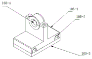
FIG. 3 is a schematic structural diagram of a soft shaft seat in a transition section;
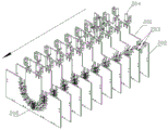
FIG. 4 is a schematic view of a plurality of forming arc plate sets in a forming section;
FIG. 5 is a front view of the mold section;
FIG. 6 is a schematic structural view of another embodiment of the shaping station;
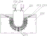
FIG. 7 is a schematic view of the drive mechanism in the forming section;
FIG. 8 is a schematic view of a position adjustment structure of a forming roller bed;
FIG. 9 is a schematic diagram of a stationary section;
FIG. 10 is a schematic structural diagram of the upper frame in the stable section;
FIG. 11 is a schematic structural diagram of a middle lower frame of a stable section;
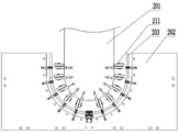
FIG. 12 is a schematic view of a wedge-shaped entrance to a stabilizer channel in a stabilizer section;
FIG. 13 is a schematic structural view of a flexible guide mechanism;
FIG. 14 is a schematic structural diagram of an upper air grid and a lower air grid when a transverse air grid is adopted in the tempering section;
FIG. 15 is a schematic structural view of an upper air grid when a transverse air grid is adopted in the tempering section;
FIG. 16 is a schematic structural view of a lower air grid when a transverse air grid is adopted in the tempering section;
FIG. 17 is a schematic view of the arrangement of the air holes in the upper air grid when the transverse air grid is adopted in the tempering section;
FIG. 18 is a schematic structural view of an upper air grid and a lower air grid when a longitudinal air grid is adopted in a tempering section;
FIG. 19 is a schematic structural diagram of a downdraft cavity when a longitudinal air grid is adopted in a toughening section;
the labels in the figure are: 1. a gradual change section, 101, a base, 102, a gradual change starting fixing plate, 103, a gradual change target arc plate, 104, a gradual change roller way, 105, a flexible shaft seat, 105-1, a T-shaped main body, 150-2, a threading groove, 105-3, a seat plate, 105-4, a bearing seat, 106, a starting roller way, 107 and a flexible cable;
2. a forming section 201, an upper forming arc plate 202, a lower forming arc plate 203, a forming roller way 204, a cylinder 205, a transmission wheel 206, a cylinder seat 207, a transition shaft 208, a transmission shaft 209, a transition wheel 210, an adjustable support 211 and a forming roller;
3. the device comprises a stabilizing section 301, an upper frame 302, a lower frame 303, an upper stabilizing mechanism 304, a lower stabilizing mechanism 305, a lifting guide mechanism 306, a lifting mechanism 307, a support frame 308, an upper stabilizing arc plate 309, a stabilizing roller way 310, a transmission chain wheel 311, an upright column 312 and a lower stabilizing arc plate; 313. a first wheel, 314, template, 315, subsequent wheel, 316, pedestal;
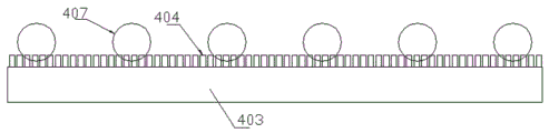
4. a tempering section 401, an upper wind cavity, 402, an upper wind box, 403, a lower wind cavity, 404, a lower wind box, 405, an upper wind hole, 406, a lower wind hole, 407 and a conveying wheel;
5. the flexible guide mechanism 501, a guide rod 502, an upper guide block 503, a fixed screw rod 504, a lower guide block 505, a lower frame 506, a spring 507 and a positioning pin;
6. and (5) finally forming the curved glass.
Detailed Description
The following detailed description of the present invention is provided with reference to the accompanying drawings and examples, but not to be construed as limiting the present invention in any way.
In the description of the present invention, it should be noted that the terms "center", "upper", "lower", "left", "right", "vertical", "horizontal", "inner", "outer", and the like indicate orientations or positional relationships based on the orientations or positional relationships shown in the drawings, and are only for convenience of description and simplification of description, but do not indicate or imply that the device or element referred to must have a specific orientation, be constructed and operated in a specific orientation, and thus, should not be construed as limiting the present invention.
In the following examples, for the sake of clarity, the target curved glass is selected to be a semi-cylindrical glass, i.e. a curved glass with a semicircular glass section, which may be a forward-curved glass or a backward-curved glass, and in this example, a forward-curved glass is used.
Referring to the attached drawing 1, the flexible shaft bent glass toughening equipment comprises a gradual change section 1, a forming section 2 and a toughening section 4, and in order to avoid the rebound deformation of the formed semi-cylindrical glass, a stabilizing section 3 can be arranged between the forming section 2 and the toughening section 4 to correct or stabilize the shape of the semi-cylindrical glass. The gradual change section 1, the forming section 2 and the stabilizing section 3 are all arranged on the forming stage rack and are sequentially arranged along the glass conveying direction, the gradual change section 1 receives hot glass coming out of the heating furnace, the stabilizing section 3 is connected with the toughening section 4, and the toughening section 4 is arranged on the toughening stage rack.
As shown in fig. 2, the gradual change section 1 includes a gradual change starting fixing plate 102 and a gradual change target arc plate 103, the gradual change starting fixing plate 102 and the gradual change target arc plate 103 are respectively disposed at two ends of a base 101, the gradual change starting fixing plate 102 has a plane for mounting a starting roller table 106 to receive and convey heated glass, the starting roller table 106 is mounted on the plane through a plurality of roller table seats, and the gradual change target arc plate 103 has an arc surface, in this embodiment, the arc surface is a concave arc surface, and can perform positive bending of glass; the plane below of the gradual change starting fixing plate 102 is provided with a plurality of round holes as connecting ends along the fixing plate length direction, the cambered surface below of the gradual change target arc plate 103 is also provided with a plurality of round holes as connecting ends along the arc of the cambered surface, and the connecting ends on the gradual change starting fixing plate 102 and the gradual change target arc plate 103 are the same in quantity, the two ends of the flexible cable 107 are respectively fixed in the round holes on the gradual change starting fixing plate 102 and the gradual change target arc plate 103, and are connected and tensioned point to point, and a plurality of gradual change roller ways 104 are arranged on the tensioned flexible cable 107 along the glass conveying direction, the gradual change roller ways 104 are installed on the flexible cable 107 through the flexible shaft seats 105, and the gradual change roller ways 104 and the flexible cable 107. And the last gradual change roller way 104 is arranged on the cambered surface of the gradual change target arc plate 103.
When the glass entering the transition section 1 has a certain radian, a bending roller way is installed on the transition starting fixing plate 102, and the shape of the bending roller way is matched with the shape of the entered glass so as to receive the glass to enter smoothly.
As shown in FIG. 3, the flexible shaft seat 105 has a T-shaped main body 105-1, the bottom of the T-shaped main body 105-1 has two threading grooves 105-2, a flexible cable 107 is threaded into each threading groove 105-2, the flexible cable 107 is clamped between the seat plate 105-3 and the T-shaped main body 105-1 through a screw, and the top end of the T-shaped main body 105-1 is provided with a bearing seat 105-4 connected with the gradual change roller way 104. A flexible cable 107 may also be connected to each flexible shaft mount 105. Only one screw is provided, which allows for a slight misalignment of the flexible cable 107, reducing the difficulty of assembly.
And the middle parts of the starting roller way 106 and the gradual change roller way 104 in the length direction are respectively provided with a transmission mechanism.
The flexible cable 107 may be a spring wire, and when the flexible cable 107 is stretched to a longer distance, the flexible cable 107 is supported by a support frame in the middle.
Gradual change section 1 is equipped with multiunit positioning mechanism, and every group positioning mechanism includes two locating wheels that are located gradual change section 1 both sides, and two locating wheels contact with the glass both sides that pass through, at glass through the in-process centre gripping glass of gradual change section 1.
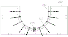
As shown in fig. 4, the shaping segment 2 includes a plurality of upper shaping arc plates 201 and a plurality of lower shaping arc plates 202, the number of the upper shaping arc plates 201 is the same as that of the lower shaping arc plates 202, or the number of the upper shaping arc plates 201 is less than that of the lower shaping arc plates 202, and each upper shaping arc plate 201 is arranged corresponding to one lower shaping arc plate 202 up and down; go up and be provided with shaping roll table 203 or a plurality of pivoted shaping gyro wheel 211 on shaping arc 201 and the lower shaping arc 202 respectively, the line of center of the shaping gyro wheel 211 that the axis of shaping roll table 203 or a plurality of interval set up suits with the arcwall face of place arc, form the shaping passageway between shaping roll table 203 or a plurality of shaping gyro wheel 211 on going up shaping arc 201 and the shaping roll table 203 or a plurality of shaping gyro wheel 211 on the lower shaping arc 202, glass after the gradual change shaping passes through the shaping passageway in-process, is extruded by the shaping roll table 203 of last shaping arc 201 and lower shaping arc and takes shape gradually, obtains the target arc.
As shown in fig. 6, as another embodiment of the forming section, a plurality of freely rotating forming rollers 211 are arranged at intervals along the arc surface of the upper forming arc plate 201, the lower forming arc plate 202 is still provided with a forming roller table 203, and the forming channel is formed between the forming rollers 211 and the forming roller table 203.
As shown in fig. 4 and 5, in order to adjust the distance between the upper forming arc plate 201 and the lower forming arc plate 202 to adapt to glasses with different thicknesses, the upper forming arc plate 201 is connected with a flexible pressing mechanism, preferably, the flexible pressing mechanism is a cylinder 204, a piston rod of the cylinder 204 is fixedly connected with the upper forming arc plate 201 through a U-shaped fork, a cylinder body of the cylinder 204 is fixed on a forming stage rack through a cylinder seat 206, and the upper forming arc plate 201 is connected with two cylinders 204 which synchronously act for the stability of the up-and-down movement of the upper forming arc plate 201; a guide device can be further arranged between the upper forming arc plate 201 and the lower forming arc plate 202, so that the upper forming arc plate 201 moves up and down along the guide device, the guide device comprises a guide sliding groove and a sliding block sliding along the guide sliding groove, the guide sliding groove is fixed on the lower forming arc plate 202, and the sliding block is fixed on the upper forming arc plate 201, so that the upper forming arc plate 201 is ensured to keep up-down corresponding relation with the lower forming arc plate 202 all the time in the process of moving up and down.
Or, the adaptation to the glass with different thicknesses can be realized by adjusting the position of the forming roller table 203 on the upper forming arc plate 201 or the lower forming arc plate 202. Specifically, as shown in fig. 8, for example, the forming arc plate 202 is described below, the forming roller table 203 is fixed on the arc surface of the lower forming arc plate 202 through an adjustable support 210, an adjusting long hole is arranged at the edge of the arc surface, the adjustable support 210 is fixed on the adjusting long hole through a bolt, the length direction of the adjusting long hole is the normal direction of the arc surface, and the adjusting support 210 can move on the adjusting long hole to adjust the installation position of the forming roller table 203.
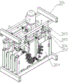
As shown in fig. 7, the transmission mechanism in the forming section 2 includes a transmission wheel 205, a transition shaft 207 and a transmission shaft 208, the transmission wheel 205 is disposed in the middle of the forming roller table 203 of the lower forming arc plate 202, the transition shaft 207 and the transmission shaft 208 are disposed in parallel on the frame, the transition shaft 207 is provided with a transition wheel 209 that is in meshing transmission with the transmission wheel 205, one shaft end of the transition shaft 207 is in meshing transmission with the shaft end of the transmission shaft 208, and the other shaft end is in transmission connection with a power mechanism on one side of the frame. The transmission wheel 205 and the transition wheel 209 adopt gears, chain wheels or belt wheels, and the shaft ends of the transition shaft 207 and the transmission shaft 208 are provided with the gears, chain wheels or belt wheels which are engaged with each other.
As shown in fig. 9, the stabilizer 3 has a separate frame and can be detachably connected to the frame at the forming stage, for example, by bolts. The stabilizing section 3 comprises an upper stabilizing mechanism 303, a lifting mechanism 306 for driving the upper stabilizing mechanism 303 to move up and down, and a lower stabilizing mechanism 304, wherein the lower stabilizing mechanism 304 and the upper stabilizing mechanism 303 extrude the formed glass through concave-convex matching so as to stabilize or correct the shape of the glass.
As shown in fig. 9 and 10, the lifting mechanism 306 adopts four cylinders which act synchronously, two cylinders are respectively arranged on two symmetrical sides of the upper frame 301, cylinder seats of the cylinders are mounted on the upper frame 301, piston rods of the cylinders are fixedly connected with the upper stabilizing mechanism 303, a support frame 307 with a frame structure is arranged on the upper portion of the upper stabilizing mechanism 303, and the piston rods are fixedly connected with the support frame 307; go up steady type mechanism 303 and include the last steady type arc 308 that sets gradually along glass direction of delivery and install the steady type roll table 309 at last steady type arc 308, go up steady type arc 308 top and install support frame 307 on, steady type roll table 309 passes through the flexible axle base and installs on the arcwall face of last steady type arc 308 bottom to form the arc identical with the arcwall face.
As shown in fig. 11, the lower stabilizing mechanism 304 includes a lower stabilizing arc plate 312 and a stabilizing roller table 309, the lower stabilizing arc plate 312 is sequentially disposed along the glass conveying direction, the bottom of the lower stabilizing arc plate 312 is mounted on the lower frame 302, two side edges of the lower stabilizing arc plate 312 are mounted between the upright posts 311 on two sides of the lower frame 302, and the stabilizing roller table 309 is mounted on the arc surface of the lower stabilizing arc plate 312 through a flexible shaft base and forms an arc shape matching with the arc surface; the stable roller table 309 comprises a flexible shaft and a roller mounted on the flexible shaft.
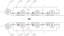
The stable roller way 309 of the upper stable mechanism 303 and the stable roller way 309 of the lower stable mechanism 304 are in up-and-down convex-concave fit to form a stable channel through which glass can pass and be precisely formed, and in order to facilitate the formed glass to smoothly enter the stable channel, an inlet of the stable channel can be designed to be a wedge-shaped inlet, as shown in fig. 12, namely, a first roller 313 at an inlet end of the stable channel is not positioned on the same straight line as a subsequent roller 315, the subsequent roller 315 and an upper roller of the stable roller way 309 are positioned on the same straight line, a distance between the first rollers 313 of the upper stable mechanism 303 and the lower stable mechanism 304 is larger than a distance between the subsequent rollers 315 of the upper stable mechanism 303 and the lower stable mechanism 304, the first rollers 313 and the subsequent rollers 315 are both installed on the plurality of upper stable arc plates 308 or the plurality of lower stable arc plates 312 through corresponding templates 314, so that a clamping groove clamped on the upper stable arc plates 308 or the lower stable arc plates 312 is arranged on the templates 314, the template 314 can also be provided with a base 316 for mounting a flexible shaft.
As shown in fig. 1, the forming stage machine frame comprises an upper machine frame and a lower machine frame, a flexible guide mechanism 5 is arranged between the upper machine frame and the lower machine frame, and the lifting device drives the upper machine frame to move up and down along the flexible guide mechanism 5.
As shown in fig. 13, the flexible guide mechanism 5 includes a guide post 501, an upper guide block 502 and a lower guide block 504, the upper end of the guide post 501 is fixedly connected with the upper frame, the upper guide block 502 is sleeved on the guide post 501, and the connection between the upper guide block 502 and the guide post 501 is realized by a positioning pin 507; the lower guide block 504 is mounted on the lower frame 505, and both the lower guide block 504 and the lower frame 505 have inner cavities for the guide posts 501 to insert and move up and down, and the position between the lower guide block 504 and the lower frame 505 is fixed; a spring 506 is arranged between the upper guide block 502 and the lower guide block 504, the spring 506 is sleeved on the guide column 501, corresponding fixing holes are respectively arranged on the flange surface of the upper guide block 502 and the flange surface of the lower guide block 504, a fixing screw 503 for fixing the distance between the upper guide block 502 and the lower guide block 504 penetrates through the fixing holes to be connected with a locking nut, and two or more fixing screws 503 can be arranged.
As shown in fig. 14, the tempering section 4 includes an upper air grid, a lower air grid and a roller conveyor, the upper air grid is provided with an upper air cavity 401 for installing an upper air box 402, the lower air grid is provided with a lower air cavity 403 for installing a lower air box 404, and a channel for swinging, blowing and cooling the target curved glass is formed between the upper air grid and the lower air grid.
As shown in fig. 15, in order to facilitate the display of the windward holes, in fig. 15, the windward grid is opposite to the use state and is inverted, the windward box 402 has a plurality of windward boxes 402 and is arranged on the lower surface of the windward cavity 401 at intervals along the glass conveying direction, the windward box 402 and the windward cavity 401 are detachably connected by bolts, each windward box 402 has a blowing surface adapted to the upper surface of the target curved glass, the windward holes 405 are arranged on the blowing surface, and the compressed air enters each windward box 402 through the windward cavity 401 and is blown to the upper surface of the target curved glass by the windward holes 405 of the windward box 402.
As shown in fig. 16, the plurality of downwind boxes 404 are arranged on the upper surface of the downwind cavity 403 at intervals along the glass conveying direction, the downwind boxes 404 and the downwind cavity 403 are detachably connected by bolts, each downwind box 404 has a blowing surface corresponding to the lower surface of the target curved glass, downwind holes 406 are arranged on the blowing surface, and compressed air enters each downwind box 404 through the downwind cavity 403 and is blown to the lower surface of the target curved glass by the downwind holes 406 of the downwind boxes 404; the rollgang is disposed between the downdraft boxes 404.
The upper wind box 402 and the lower wind box 404 are arranged up and down correspondingly, in this embodiment, the wind blowing surface of the upper wind box 402 and the wind blowing surface of the lower wind box 404 and the target curved glass passing through belong to concentric circles.
Along the conveying direction of the glass, the plurality of windward boxes 402 are divided into a plurality of windward box groups, each windward box group is composed of the same number of windward boxes 402, and the arrangement modes of the windward holes 405 of any two windward box groups are the same.
The arrangement of the above-mentioned air holes 405 is explained in detail by a specific air grid structure as follows.
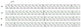
As shown in fig. 15, 12 windward boxes 402 are arranged in the windward fence, and 4 windward boxes 402 are grouped into 3 windward box groups. Taking one of the upwind box groups, spreading the blowing surfaces of the 4 upwind boxes 402 to obtain a rectangular blowing surface spreading diagram, as shown in fig. 17, taking the 4 blowing surface spreading diagrams as a group, respectively named as upper a, upper B, upper C and upper D, wherein the upwind holes on each blowing surface spreading diagram are arranged in 3 rows (along the width direction of the blowing surface spreading diagram, i.e. the glass conveying direction), as can be seen from the diagram, the 3 rows of upwind holes 405 are arranged in a staggered manner along the glass conveying direction, and the positions of the same rows of upwind holes 405 in different upwind boxes 402 (i.e. different blowing surface spreading diagrams) are arranged in a staggered manner along the glass conveying direction. The other two windward box groups are arranged at the positions of the windward holes according to the arrangement of the windward holes 405 at the upper A, the upper B, the upper C and the upper D.
In the lower air grid, the lower air holes 406 of the lower air box 404 are arranged in the same manner, so that the upper air holes 405 and the lower air holes 406 can realize full-coverage air blowing on the upper surface and the lower surface of the glass, the situation that the glass is blown for many times at the same position can be avoided on the premise that the air holes are arranged as much as possible, the uniformity of air blowing and cooling of the glass is improved, and the occurrence of wind spots is reduced.
In the above embodiments, the upper air grid and the lower air grid are both transverse air grids, that is, the air holes on each air box are arranged along the direction perpendicular to the glass conveying direction. In addition, the upper air grid and the lower air grid can also be longitudinal air grids, and the structure of the longitudinal air grids is as follows: the upper air grid comprises a plurality of upper air cavities 401 which are arranged at intervals along the direction vertical to the glass conveying direction, the length direction of each upper air cavity 401 is parallel to the glass conveying direction, at least one row of upper air boxes 402 are arranged on the lower surfaces of the upper air cavities 401 along the glass conveying direction, and the upper air holes are formed in the upper air boxes 402; the downwind fence comprises a plurality of downwind cavities 403 which are arranged at intervals along the direction perpendicular to the glass conveying direction, the length direction of the downwind cavities 403 is parallel to the glass conveying direction, at least one row of downwind boxes 404 are arranged on the upper surface of the downwind cavities 403 along the glass conveying direction, and downwind holes are formed in the downwind boxes 404.
The blowing surface of the upper air cavity 401 and the blowing surface of the lower air cavity 403 are both provided with a plurality of conveying wheels 407, the conveying wheels 407 are arranged at intervals along the glass conveying direction, and the end parts of at least one lower air cavity 403 and the corresponding upper air cavity 401 are provided with conveying wheel driving mechanisms.
When the number of the plurality of upwind cavities 401 and the number of the plurality of downwind cavities 403 are even, in the direction perpendicular to the glass movement direction, the two downwind cavities 403 at the two ends and the end parts of the corresponding upwind cavities 401 are provided with a conveyor wheel driving mechanism.
When the number of the plurality of upwind cavities 401 and the number of the plurality of downwind cavities 403 are both odd, in a direction perpendicular to the moving direction of the glass, the end portions of the two downwind cavities 403 at the two extreme ends and the downwind cavity 403 at the middle portion are provided with a conveyor wheel driving mechanism, and the end portions of the upwind cavities 401 corresponding to the two downwind cavities 403 at the extreme ends and the downwind cavity 403 at the middle portion are also provided with a conveyor wheel driving mechanism.
The conveying wheel driving mechanism can be a motor, the motor drives the conveying wheel 407 at one end of the upper air cavity 401 or the lower air cavity 403 to rotate, the conveying wheel 407 is a driving wheel, and the other conveying wheels 407 on the upper air cavity 401 or the lower air cavity 403 are in transmission connection with the driving wheel through a chain wheel and chain mechanism, so that the rotation of the conveying wheel 407 on the upper air cavity 401 or the lower air cavity 403 is realized.
The "lateral direction" described above refers to a direction perpendicular to the glass conveying direction, and the "longitudinal direction" refers to a direction parallel to the glass conveying direction.
A bending and toughening forming method of a columnar glass flexible shaft utilizes the bending and toughening equipment of the columnar glass flexible shaft, and comprises the following steps:
and (3) a gradual change stage: the hot glass is preliminarily formed in the process of forming the net through the gradual change section 1, and the linear change of the curvature of the glass is realized, and the section shape of the glass after preliminary forming is ︶ shape, cutting preference shape or wave shape;
and (3) forming: the glass after preliminary forming is conveyed into a forming section 2, and formed curved glass is formed after passing through a forming channel of the forming section 2, and the formed curved glass has the same section shape and higher forming precision as the glass after preliminary forming;
and (3) a model stabilizing stage: the formed curved glass is sent out from the forming section 2 and enters the stabilizing section 3, the shape of a stabilizing roller way 309 in the stabilizing section 3 is matched with the cross section shape of the target curved glass, the shape of the formed curved glass is further stabilized and corrected, and the formed curved glass is finally formed into the curved glass 6;
when the glass size is smaller, the forming process can be completed directly through the forming section 2 without arranging the stabilizing section 3, and the method used in the process is as follows: a flexible shaft bent glass toughening forming method comprises the following steps:
and (3) a gradual change stage: the hot glass is preliminarily formed in the process of forming the net through the gradual change section 1, and the linear change of the curvature of the glass is realized, and the section shape of the glass after preliminary forming is ︶ shape, cutting preference shape or wave shape;
and (3) forming: the preliminarily molded glass is conveyed into the molding section 2, and finally molded curved glass 6 is formed after passing through a molding channel of the molding section 2, wherein the finally molded curved glass 6 has the same section shape and higher molding precision as the preliminarily molded glass;
a toughening stage: and sending the finally formed curved glass 6 into the tempering section 4 for air-blowing tempering to obtain the target curved glass.
Regardless of the method used, the glass needs to be clamped between positioning wheels on both sides of the transition section 1 during the movement of the glass through the transition section 1 to complete the positioning of the glass.
When the method with the stabilizing section, namely the first method described in this embodiment, is adopted, the curvature of the preliminarily molded glass is defined as K1, the curvature of the molded curved glass is defined as K2, the curvature of the finally molded curved glass is defined as K3, and the curvature of the target curved glass is defined as K4; the magnitude relationships of K1, K2, K3, and K4 are as follows: k2 is more than K1 and less than or equal to K3, and K3 is equal to K4.
When the method without the stable section, namely the second method described in this embodiment, is adopted, the curvature of the preliminarily molded glass is defined as K1, the curvature of the finally molded curved glass is defined as K3, and the curvature of the target curved glass is defined as K4; the magnitude relationships of K1, K3 and K4 at this time are as follows: k1 < K3 ═ K4.
Because the stable sections 3 in the equipment are detachably connected, when two target curved glass with different curvatures are needed to be laminated, the stable sections 3 with different specifications can be replaced after the stable section 3 with one specification is used for production; the two types of stable sections refer to that the curvatures of the arc surfaces of the upper stable arc plate 308 and the lower stable arc plate 312 in the stable section 3 are different, so that the curvatures of the arcs formed after the stable roller way 309 is bent are also different, and two types of semicircular glass 6 with different curvatures can be produced and can be used for laminated glass or hollow laminated sheets.
Although embodiments have been described with reference to a number of illustrative embodiments, it should be understood that numerous other modifications and embodiments can be devised by those skilled in the art that will fall within the spirit and scope of the principles of this disclosure. More specifically, various variations and modifications are possible in the component parts and/or arrangements of the subject combination arrangement within the scope of the disclosure, the drawings and the appended claims. In addition to variations and modifications in the component parts and/or arrangements, other uses will also be apparent to those skilled in the art.
Claims (12)
1. The utility model provides a curved glass tempering equipment of flexible axle, includes gradual change section (1), shaping section (2) and tempering section (4), its characterized in that: the gradual change section (1) comprises a gradual change starting fixing plate (102), a gradual change target arc plate (103), a plurality of tensioned flexible cables (107) connecting the gradual change starting fixing plate (102) and the gradual change target arc plate (103), and a gradual change roller way (104) arranged on the flexible cables (107), wherein the flexible cables (107) and the gradual change roller way (104) construct a forming net, and the shape of the arc surface of the gradual change target arc plate (103) is adapted to the shape of the surface of the glass to be formed; the forming section (2) is provided with a plurality of upper forming arc plates (201) and a plurality of lower forming arc plates (202), the number of the upper forming arc plates (201) and the number of the lower forming arc plates (202) are the same or the number of the upper forming arc plates (201) is less than that of the lower forming arc plates (202), and each upper forming arc plate (201) and one lower forming arc plate (202) are arranged in an up-and-down corresponding mode; go up and be provided with shaping roll table (203) or a plurality of pivoted shaping gyro wheel (211) on shaping arc board (201) and lower shaping arc board (202) respectively, the central line of the axis of shaping roll table (203) or the shaping gyro wheel (211) that a plurality of intervals set up suits with the arcwall face of place arc board, form the shaping passageway between shaping roll table (203) or a plurality of shaping gyro wheel (211) on going up shaping arc board (201) and shaping roll table (203) or a plurality of shaping gyro wheel (211) on lower shaping arc board (202).
2. The flexible shaft bent glass toughening equipment of claim 1, wherein: a plurality of connecting ends are arranged on the gradual change target arc plate (103) and the gradual change initial fixing plate (102), the connecting ends on the gradual change initial fixing plate (102) are sequentially arranged along the edge of the gradual change initial fixing plate (102), the connecting ends on the gradual change target arc plate (103) are sequentially arranged along the edge of an arc section of the gradual change target arc plate (103), and a plurality of connecting ends on the gradual change initial fixing plate (102) and a plurality of connecting ends on the gradual change target arc plate (103) are connected with a plurality of tensioned flexible cables (107); a plurality of flexible shaft seats (105) are arranged on the flexible cable (107) along the length direction of the flexible cable, and the gradual change roller way (104) is connected with the flexible cables (107) through the flexible shaft seats.
3. The flexible shaft bent glass toughening equipment of claim 1, wherein: the gradual change starting fixing plate (102) is provided with a starting roller way (106), the starting roller way (106) is a linear roller way or a bending roller way, and the curvature of the bending roller way is based on the principle that heated glass can smoothly enter the bending roller way.
4. The flexible shaft bent glass toughening equipment of claim 1, wherein: gradual change section (1) is equipped with multiunit positioning mechanism, and every group positioning mechanism includes two locating wheels that are located gradual change section (1) both sides, and two locating wheels contact with the glass both sides limit portion that passes through, at the in-process centre gripping glass that glass passes through gradual change section (1).
5. The flexible shaft bent glass toughening equipment of claim 1, wherein: the transmission mechanism in the forming section (2) comprises a transmission wheel (205), a transition shaft (207) and a transmission shaft (208), the transmission wheel (205) is arranged in the middle of the forming roller way (203), the transition shaft (207) and the transmission shaft (208) are arranged on the rack in parallel, and the power of the power mechanism is transmitted to the transmission wheel (205) through the transmission shaft (208) and the transition shaft (207).
6. The flexible shaft bent glass toughening equipment of claim 1, wherein: in the forming section (2), a flexible shaft in a forming roller way (203) is installed on an upper forming arc plate (201) and a lower forming arc plate (202) through an adjustable support (210), and the adjustable support (210) can slide on the upper forming arc plate (201) or the lower forming arc plate (202) to adjust the size of a gap between the forming roller way (203) on the upper forming arc plate (201) and the lower forming arc plate (202).
7. The flexible shaft bent glass toughening equipment of claim 1, wherein: the tempering section (4) comprises an upper air grid and a lower air grid which are arranged up and down correspondingly, and the upper air grid and the lower air grid are provided with air blowing surfaces which are matched with the surface shape of the bent glass to be molded; the upper air grid and the lower air grid are arranged at intervals along the glass conveying direction or are arranged at intervals along the direction vertical to the glass conveying direction.
8. The flexible shaft bent glass toughening equipment of claim 7, wherein: the glass conveying device is characterized in that a plurality of conveying wheels (407) are arranged on the blowing surfaces of the upper air grid and the lower air grid, the conveying wheels (407) are arranged at intervals along the glass conveying direction, and a conveying wheel driving mechanism is arranged at the end part of at least one lower air grid and the corresponding upper air grid.
9. The flexible shaft bent glass toughening equipment of claim 1, wherein: still be equipped with between shaping section (2) and tempering section (4) and stabilize section (3), steady section (3) detachable install in the frame of shaping section (2) exit end to link up with tempering section (4).
10. The flexible shaft bent glass toughening equipment of claim 9, wherein: the shape stabilizing section (3) comprises an upper shape stabilizing mechanism (303), a lifting mechanism (306) for driving the upper shape stabilizing mechanism (303) to move up and down, and a lower shape stabilizing mechanism (304), wherein the lower shape stabilizing mechanism (304) and the upper shape stabilizing mechanism (303) are both provided with cambered surfaces adaptive to the surface shape of the bent glass to be molded.
11. The flexible shaft bent glass toughening equipment of claim 10, wherein: the upper stabilizing mechanism (303) and the lower stabilizing mechanism (304) of the stabilizing section (3) are vertically matched to form a channel for glass to pass through, and the inlet of the channel is a wedge-shaped inlet which is reduced from outside to inside.
12. The flexible shaft bent glass toughening equipment of claim 1, wherein: the shape of the arc surface of the gradual change target arc plate (103) is '︶', a 'cutting preference' or a wave shape.
Priority Applications (1)
| Application Number | Priority Date | Filing Date | Title |
|---|---|---|---|
| CN201921306495.5U CN211078892U (en) | 2019-08-13 | 2019-08-13 | Flexible shaft bent glass toughening equipment |
Applications Claiming Priority (1)
| Application Number | Priority Date | Filing Date | Title |
|---|---|---|---|
| CN201921306495.5U CN211078892U (en) | 2019-08-13 | 2019-08-13 | Flexible shaft bent glass toughening equipment |
Publications (1)
| Publication Number | Publication Date |
|---|---|
| CN211078892U true CN211078892U (en) | 2020-07-24 |
Family
ID=71638743
Family Applications (1)
| Application Number | Title | Priority Date | Filing Date |
|---|---|---|---|
| CN201921306495.5U Withdrawn - After Issue CN211078892U (en) | 2019-08-13 | 2019-08-13 | Flexible shaft bent glass toughening equipment |
Country Status (1)
| Country | Link |
|---|---|
| CN (1) | CN211078892U (en) |
Cited By (2)
| Publication number | Priority date | Publication date | Assignee | Title |
|---|---|---|---|---|
| CN110498594A (en) * | 2019-08-13 | 2019-11-26 | 洛阳兰迪玻璃机器股份有限公司 | A kind of curved glass fibre reinforced plastic equipment of flexible axle and forming method |
| CN115353280A (en) * | 2022-09-05 | 2022-11-18 | 安徽明玻玻璃科技有限公司 | Softening equipment for producing uniformly-heated toughened glass based on rotation adjustment |
-
2019
- 2019-08-13 CN CN201921306495.5U patent/CN211078892U/en not_active Withdrawn - After Issue
Cited By (2)
| Publication number | Priority date | Publication date | Assignee | Title |
|---|---|---|---|---|
| CN110498594A (en) * | 2019-08-13 | 2019-11-26 | 洛阳兰迪玻璃机器股份有限公司 | A kind of curved glass fibre reinforced plastic equipment of flexible axle and forming method |
| CN115353280A (en) * | 2022-09-05 | 2022-11-18 | 安徽明玻玻璃科技有限公司 | Softening equipment for producing uniformly-heated toughened glass based on rotation adjustment |
Similar Documents
| Publication | Publication Date | Title |
|---|---|---|
| CN110498594B (en) | Flexible shaft bent glass tempering equipment and forming method | |
| WO2020156376A1 (en) | Forming apparatus for curved tempered glass, and forming method | |
| CN209890490U (en) | Curved toughened glass former | |
| CN211078892U (en) | Flexible shaft bent glass toughening equipment | |
| CN203393014U (en) | Double-curved-surface tempered glass production equipment | |
| CN212425857U (en) | Toughened glass's shaping tempering equipment | |
| CA2567605C (en) | Apparatus and method for glass sheet forming with cross curvature | |
| CN108545913B (en) | Spherical toughened glass production device and method | |
| CN111348820B (en) | Rotary type transition section for bent glass forming and tempering forming equipment | |
| CN110434188A (en) | A kind of online apparatus for shaping of aluminium high temperature and a kind of aluminium post forming method | |
| CN211078904U (en) | Longitudinal air grid for curved glass tempering | |
| CN217628108U (en) | Gradual change flexible axle curved tempering equipment | |
| US7086252B2 (en) | System and method for continuous forming of glass sheets | |
| CN211078891U (en) | Curved surface toughened glass's former | |
| CN201006857Y (en) | Equipment for bending vehicle glass into section steel | |
| CN211078889U (en) | Curved toughened glass gradual change former | |
| CN210945355U (en) | Bent toughened glass forming precision adjusting mechanism | |
| CN209890496U (en) | Upper air grid longitudinal arc forming mechanism | |
| CN219079345U (en) | Multistage type neck pressing mechanism of horizontal ampoule machine | |
| CN110429349B (en) | Method and mechanism for correcting pole of storage battery | |
| CN220008806U (en) | Film blowing frame | |
| CN218951247U (en) | Air grid quenching feeding mechanism of glass tempering furnace | |
| CN216732333U (en) | Wet blank corrector for cement fiber vacuum extrusion plate | |
| CN219469928U (en) | Cooling air grid for glass tempering | |
| CN219214156U (en) | Preformed universal frame matched with glass fiber reinforced plastic pultrusion die |
Legal Events
| Date | Code | Title | Description |
|---|---|---|---|
| GR01 | Patent grant | ||
| GR01 | Patent grant | ||
| AV01 | Patent right actively abandoned |
Granted publication date: 20200724 Effective date of abandoning: 20230725 |
|
| AV01 | Patent right actively abandoned |
Granted publication date: 20200724 Effective date of abandoning: 20230725 |
|
| AV01 | Patent right actively abandoned | ||
| AV01 | Patent right actively abandoned |