CN211077993U - Wire and cable coiling mechanism convenient to remove - Google Patents
Wire and cable coiling mechanism convenient to remove Download PDFInfo
- Publication number
- CN211077993U CN211077993U CN201921298811.9U CN201921298811U CN211077993U CN 211077993 U CN211077993 U CN 211077993U CN 201921298811 U CN201921298811 U CN 201921298811U CN 211077993 U CN211077993 U CN 211077993U
- Authority
- CN
- China
- Prior art keywords
- block
- fixedly connected
- base
- movably connected
- fixed
- Prior art date
- Legal status (The legal status is an assumption and is not a legal conclusion. Google has not performed a legal analysis and makes no representation as to the accuracy of the status listed.)
- Expired - Fee Related
Links
Images

Abstract
The utility model discloses an electric wire and cable coiling mechanism convenient to remove, the on-line screen storage device comprises a base, the top fixedly connected with fixed block of base, the top fixedly connected with connecting block of fixed block, the first motor of right side fixedly connected with at connecting block top, the equal swing joint in both sides of base inside has the pulley, the surface of pulley has the supporting shoe through round pin axle swing joint. The utility model discloses a set up first motor and dead lever, can make the reel rotate, through setting up the slider, the connecting rod, the supporting shoe, the bracing piece, the fixed plate, the second motor, second gear and first gear, can make the movable block remove about, through setting up the support, the bolt, gyro wheel and inserted bar, it is convenient for remove to make the coiling mechanism, make wire and cable coiling mechanism convenient to use, wire and cable coiling mechanism is convenient for transport, improve production efficiency, and the reel can be adjusted according to winding cable specification and length, be favorable to people's use.
Description
Technical Field
The utility model relates to a cable rolling technical field specifically is a wire and cable coiling mechanism convenient to remove.
Background
The wire and cable is used for transmitting electric energy, information and wire products for realizing electromagnetic energy conversion, the cable is generally a cable similar to a rope formed by twisting a plurality of or a plurality of groups of wires, each group of cables is insulated from each other and is usually twisted around a center, the whole outer surface is wrapped with a highly-insulated covering layer, the cable has the characteristics of internal electrification and external insulation, in the cable production process, a cable winder is needed to wind the cable, a strip-shaped cable is wound into a bundle shape to be stored, the cable is wound into the bundle shape to be convenient to store, the cable is convenient to transport, on one hand, the position of the cable cannot be randomly moved according to needs in the winding process, inconvenience is brought to the work of people, the production efficiency is influenced, on the other hand, the existing winding drum has a fixed structure, and the size of the winding drum cannot be adjusted according to the specification and the length of the wound cable, is not beneficial to the use of people.
SUMMERY OF THE UTILITY MODEL
An object of the utility model is to provide a wire and cable coiling mechanism convenient to remove possesses wire and cable coiling mechanism convenient to use's advantage, has solved wire and cable coiling mechanism and has used inconvenient problem.
In order to achieve the above object, the utility model provides a following technical scheme: a wire and cable winding device convenient to move comprises a base, wherein the top of the base is fixedly connected with a fixed block, the top of the fixed block is fixedly connected with a connecting block, the right side of the top of the connecting block is fixedly connected with a first motor, two sides of the interior of the base are movably connected with pulleys, the surfaces of the pulleys are movably connected with supporting blocks through pin shafts, the tops of the supporting blocks penetrate through the base and extend to the exterior of the base, two sides of the top of the base are fixedly connected with fixed plates, one side of each fixed plate is movably connected with a fixed rod, the surface of a rotating shaft of the first motor is in transmission connection with the fixed rod through a belt, a winding drum is fixedly connected between the two fixed rods, the surface of the winding drum is movably connected with a movable block, the interior of the movable, the other end of connecting rod runs through the movable block and extends to the outside and the supporting shoe fixed connection of movable block, swing joint has the bracing piece between two fixed plates, the fixed surface of bracing piece is connected with first gear, the surface of bracing piece and the inner wall threaded connection of supporting shoe, the positive top fixedly connected with second motor of fixed block, the front end fixedly connected with second gear of second motor shaft, the surface and the first gear engagement of second gear, the equal swing joint in both sides at base top has the bolt, the surface threaded connection of bolt has the support, one side of support has the gyro wheel through round pin axle swing joint, the inside swing joint of base has the inserted bar, the top of inserted bar extends to the outside of bolt.
Preferably, a sliding groove is formed in the movable block, and the inner wall of the sliding groove is movably connected with the surface of the sliding block.
Preferably, the base is internally provided with a groove, and the inner wall of the groove is movably connected with the surface of the pulley.
Preferably, both sides of the interior of the winding drum are movably connected with guide blocks, and the front surfaces of the guide blocks are fixedly connected with the inner walls of the movable blocks.
Preferably, the surface of the roller is fixedly connected with a rubber sleeve, and the surface of the rubber sleeve is provided with anti-skid lines.
Compared with the prior art, the beneficial effects of the utility model are as follows:
1. the utility model discloses a set up first motor and dead lever, can make the reel rotate, through setting up the slider, the connecting rod, the supporting shoe, the bracing piece, the fixed plate, the second motor, second gear and first gear, can make the movable block remove about, through setting up the support, the bolt, gyro wheel and inserted bar, it is convenient for remove to make the coiling mechanism, make wire and cable coiling mechanism convenient to use, wire and cable coiling mechanism is convenient for transport, improve production efficiency, and the reel can be adjusted according to winding cable specification and length, be favorable to people's use.
2. The utility model discloses a set up the spout, make the slider remove more stably, through setting up the recess, make the pulley remove more stably, through setting up the guide block, make the movable block can follow the reel and rotate, through setting up the rubber sleeve, reduce the noise that produces when the coiling mechanism removed.
Drawings
FIG. 1 is a schematic structural view of the present invention;
fig. 2 is a sectional view of the structure movable block of the present invention.
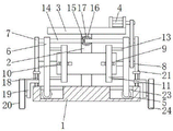
In the figure: 1. a base; 2. a fixed block; 3. connecting blocks; 4. a first motor; 5. a pulley; 6. a support block; 7. a fixing plate; 8. fixing the rod; 9. a reel; 10. a guide block; 11. a movable block; 12. a slider; 13. a connecting rod; 14. a support bar; 15. a first gear; 16. a second motor; 17. a second gear; 18. a bolt; 19. a support; 20. a roller; 21. inserting a rod; 22. a chute; 23. a groove; 24. a rubber sleeve.
Detailed Description
The technical solutions in the embodiments of the present invention will be described clearly and completely with reference to the accompanying drawings in the embodiments of the present invention, and it is obvious that the described embodiments are only some embodiments of the present invention, not all embodiments. Based on the embodiments in the present invention, all other embodiments obtained by a person skilled in the art without creative work belong to the protection scope of the present invention.
Referring to fig. 1-2, an electric wire and cable winding device convenient to move comprises a base 1, a groove 23 is formed in the base 1, the inner wall of the groove 23 is movably connected with the surface of a pulley 5, the pulley 5 is more stably moved by arranging the groove 23, a fixed block 2 is fixedly connected with the top of the base 1, a connecting block 3 is fixedly connected with the top of the fixed block 2, a first motor 4 is fixedly connected with the right side of the top of the connecting block 3, pulleys 5 are movably connected with both sides of the inside of the base 1, a supporting block 6 is movably connected with the surface of the pulley 5 through a pin shaft, the top of the supporting block 6 penetrates through the base 1 and extends to the outside of the base 1, fixing plates 7 are fixedly connected with both sides of the top of the base 1, a fixing rod 8 is movably connected with one side of the fixing plate 7, the surface of a rotating shaft of the first motor, the two sides inside the winding drum 9 are movably connected with guide blocks 10, the front of each guide block 10 is fixedly connected with the inner wall of a movable block 11, the movable block 11 can rotate along with the winding drum 9 by arranging the guide blocks 10, the surface of the winding drum 9 is movably connected with the movable block 11, a sliding groove 22 is formed inside each movable block 11, the inner wall of each sliding groove 22 is movably connected with the surface of a sliding block 12, the sliding block 12 can move more stably by arranging the sliding groove 22, the sliding block 12 is movably connected inside the movable block 11, one side of the sliding block 12 is fixedly connected with a connecting rod 13, the other end of the connecting rod 13 penetrates through the movable block 11 and extends to the outside of the movable block 11 to be fixedly connected with a supporting block 6, a supporting rod 14 is movably connected between two fixing plates 7, the surface of the supporting rod 14 is fixedly connected with a first gear 15, the surface of the supporting rod 14 is in threaded connection, the front end of the rotating shaft of the second motor 16 is fixedly connected with a second gear 17, the surface of the second gear 17 is meshed with a first gear 15, both sides of the top of the base 1 are movably connected with bolts 18, the surface of each bolt 18 is in threaded connection with a support 19, one side of each support 19 is movably connected with a roller 20 through a pin shaft, the surface of each roller 20 is fixedly connected with a rubber sleeve 24, the surface of each rubber sleeve 24 is provided with anti-skid grains, the rubber sleeves 24 are arranged to reduce noise generated when the winding device moves, the inner part of the base 1 is movably connected with an inserted bar 21, the top end of each inserted bar 21 extends to the outer part of each bolt 18, the winding drum 9 can be rotated through arranging the first motor 4 and the fixed bar 8, the sliding block 12, the connecting bar 13, the supporting block 6, the supporting bar 14, the fixed plate 7, the second motor 16, the second gear 17 and the first, through setting up support 19, bolt 18, gyro wheel 20 and inserted bar 21, make the coiling mechanism be convenient for remove, make wire and cable coiling mechanism convenient to use, wire and cable coiling mechanism is convenient for transport, improves production efficiency, and reel 9 can adjust according to winding cable specification and length, is favorable to people's use.
During the use, start first motor 4, first motor 4 drives dead lever 8 through the belt and rotates, dead lever 8 drives reel 9 and rotates, roll up wire and cable, start second motor 16, second motor 16 drives second gear 17 and rotates, second gear 17 drives bracing piece 14 through first gear 15 and rotates, bracing piece 14 drives the supporting shoe 6 and removes, supporting shoe 6 drives connecting rod 13 and slider 12 and removes, slider 12 drives movable block 11 horizontal rotation, make wire and cable coiling mechanism convenient to use, wire and cable coiling mechanism is convenient for transport, and the production efficiency is improved, and reel 9 can be adjusted according to winding cable specification and length, be favorable to people's use.
Although embodiments of the present invention have been shown and described, it will be appreciated by those skilled in the art that changes, modifications, substitutions and alterations can be made in these embodiments without departing from the principles and spirit of the invention, the scope of which is defined in the appended claims and their equivalents.
Claims (5)
1. The utility model provides a wire and cable coiling mechanism convenient to remove, includes base (1), its characterized in that: the top of the base (1) is fixedly connected with a fixed block (2), the top of the fixed block (2) is fixedly connected with a connecting block (3), the right side of the top of the connecting block (3) is fixedly connected with a first motor (4), two sides of the inside of the base (1) are both movably connected with pulleys (5), the surface of each pulley (5) is movably connected with a supporting block (6) through a pin shaft, the top of each supporting block (6) penetrates through the base (1) and extends to the outside of the base (1), two sides of the top of the base (1) are both fixedly connected with fixed plates (7), one side of each fixed plate (7) is movably connected with a fixed rod (8), the surface of a rotating shaft of the first motor (4) is in transmission connection with the fixed rods (8) through a belt, a winding drum (9) is fixedly connected between the two fixed rods (8), and the surface of, the inner part of the movable block (11) is movably connected with a sliding block (12), one side of the sliding block (12) is fixedly connected with a connecting rod (13), the other end of the connecting rod (13) penetrates through the movable block (11) and extends to the outer part of the movable block (11) to be fixedly connected with a supporting block (6), a supporting rod (14) is movably connected between two fixing plates (7), a first gear (15) is fixedly connected to the surface of the supporting rod (14), the surface of the supporting rod (14) is in threaded connection with the inner wall of the supporting block (6), the front top of the fixed block (2) is fixedly connected with a second motor (16), the front end of a rotating shaft of the second motor (16) is fixedly connected with a second gear (17), the surface of the second gear (17) is meshed with the first gear (15), and both sides of the top of the base (1) are movably connected with bolts (, the surface threaded connection of bolt (18) has support (19), one side of support (19) has gyro wheel (20) through round pin axle swing joint, the inside swing joint of base (1) has inserted bar (21), the top of inserted bar (21) extends to the outside of bolt (18).
2. A portable wire and cable take-up device as claimed in claim 1, wherein: a sliding groove (22) is formed in the movable block (11), and the inner wall of the sliding groove (22) is movably connected with the surface of the sliding block (12).
3. A portable wire and cable take-up device as claimed in claim 1, wherein: a groove (23) is formed in the base (1), and the inner wall of the groove (23) is movably connected with the surface of the pulley (5).
4. A portable wire and cable take-up device as claimed in claim 1, wherein: the equal swing joint in both sides of reel (9) inside has guide block (10), the front of guide block (10) and the inner wall fixed connection of movable block (11).
5. A portable wire and cable take-up device as claimed in claim 1, wherein: the surface of the roller (20) is fixedly connected with a rubber sleeve (24), and anti-skid lines are arranged on the surface of the rubber sleeve (24).
Priority Applications (1)
| Application Number | Priority Date | Filing Date | Title |
|---|---|---|---|
| CN201921298811.9U CN211077993U (en) | 2019-08-12 | 2019-08-12 | Wire and cable coiling mechanism convenient to remove |
Applications Claiming Priority (1)
| Application Number | Priority Date | Filing Date | Title |
|---|---|---|---|
| CN201921298811.9U CN211077993U (en) | 2019-08-12 | 2019-08-12 | Wire and cable coiling mechanism convenient to remove |
Publications (1)
| Publication Number | Publication Date |
|---|---|
| CN211077993U true CN211077993U (en) | 2020-07-24 |
Family
ID=71644535
Family Applications (1)
| Application Number | Title | Priority Date | Filing Date |
|---|---|---|---|
| CN201921298811.9U Expired - Fee Related CN211077993U (en) | 2019-08-12 | 2019-08-12 | Wire and cable coiling mechanism convenient to remove |
Country Status (1)
| Country | Link |
|---|---|
| CN (1) | CN211077993U (en) |
Cited By (1)
| Publication number | Priority date | Publication date | Assignee | Title |
|---|---|---|---|---|
| CN112915269A (en) * | 2021-01-12 | 2021-06-08 | 郭超凡 | Peritoneal effusion collection system for gastroenterology |
-
2019
- 2019-08-12 CN CN201921298811.9U patent/CN211077993U/en not_active Expired - Fee Related
Cited By (2)
| Publication number | Priority date | Publication date | Assignee | Title |
|---|---|---|---|---|
| CN112915269A (en) * | 2021-01-12 | 2021-06-08 | 郭超凡 | Peritoneal effusion collection system for gastroenterology |
| CN112915269B (en) * | 2021-01-12 | 2022-08-23 | 蔡芳芳 | Peritoneal effusion collection system for gastroenterology |
Similar Documents
| Publication | Publication Date | Title |
|---|---|---|
| CN206814157U (en) | A kind of variable cable take-up of wire spool size and laying apparatu | |
| CN109411157B (en) | Wire stranding equipment for producing wires and cables | |
| CN211110391U (en) | Wire rope is with receiving and releasing device for elevator | |
| CN110683413A (en) | Coiling mechanism is used in production of anti-winding's built on stilts insulated cable of combination formula | |
| CN112374301A (en) | Cable rolling transportation system for new energy distribution network | |
| CN211077993U (en) | Wire and cable coiling mechanism convenient to remove | |
| CN216311447U (en) | Cable production stranded conductor device | |
| CN214399321U (en) | Cable winding device convenient to move and provided with anti-winding structure | |
| CN212101487U (en) | Portable electric wire winding and unwinding devices for power transmission and transformation engineering | |
| CN217437388U (en) | Communication cable winding and unwinding devices for communication engineering | |
| CN214827977U (en) | Steel-cored aluminum strand winding device | |
| CN214588222U (en) | Cable production stranded conductor device | |
| CN214003703U (en) | Cable winding and unwinding devices for communication engineering winding displacement | |
| CN114955705A (en) | Wire and cable processing production equipment capable of avoiding winding | |
| CN210914754U (en) | Cable production equipment convenient to it is portable | |
| CN212659356U (en) | Aluminum alloy cable stranding equipment | |
| CN206502459U (en) | A kind of power cable retracting device | |
| CN214410866U (en) | A wire machine for cable manufacture | |
| CN213037186U (en) | Power cable's coiling mechanism | |
| CN219585542U (en) | Multi-cable winding and coiling device | |
| CN215118461U (en) | Novel cable-former for processing cable and wire | |
| CN217902805U (en) | Cable production stranded conductor device | |
| CN218491149U (en) | Electric power cable coiling apparatus convenient to transport | |
| CN216697970U (en) | Fork-type wire stranding machine for wire production | |
| CN213201962U (en) | Pay-off is used in electric power construction |
Legal Events
| Date | Code | Title | Description |
|---|---|---|---|
| GR01 | Patent grant | ||
| GR01 | Patent grant | ||
| CF01 | Termination of patent right due to non-payment of annual fee |
Granted publication date: 20200724 Termination date: 20210812 |
|
| CF01 | Termination of patent right due to non-payment of annual fee |