CN211071092U - Environment-friendly silicon wafer cleaning machine - Google Patents
Environment-friendly silicon wafer cleaning machine Download PDFInfo
- Publication number
- CN211071092U CN211071092U CN201921911010.5U CN201921911010U CN211071092U CN 211071092 U CN211071092 U CN 211071092U CN 201921911010 U CN201921911010 U CN 201921911010U CN 211071092 U CN211071092 U CN 211071092U
- Authority
- CN
- China
- Prior art keywords
- silicon wafer
- clamping plate
- cleaning machine
- environment
- casing
- Prior art date
- Legal status (The legal status is an assumption and is not a legal conclusion. Google has not performed a legal analysis and makes no representation as to the accuracy of the status listed.)
- Active
Links
Images

Abstract
The utility model discloses an environment-friendly silicon wafer cleaning machine, which comprises a shell, a supporting leg and an upper cover, wherein the bottom end of the shell is fixedly provided with a stirring motor, the output end of the stirring motor penetrates through the shell to the inside of the shell, the output end of the stirring motor is connected with a silicon wafer fixing device, a front splint on the silicon wafer fixing device is hinged with a rear splint, and the size of the front splint is the same as that of the rear splint; the lock lugs are welded on two sides of the front clamping plate; the lock catches are welded on two sides of the rear clamping plate and matched with the lock lugs; the connecting post rod is welded in the middle of the front clamping plate; the draw-in groove adopts a plurality ofly, and front splint and back splint all adopt hollow out construction, and shells inner wall is fixed all around and is equipped with electric heater, and shells inner wall bottom is fixed and is equipped with supersonic generator, and shells side wall upper end is provided with the inlet tube, and the filler pipe still is equipped with the blast pipe to opposite casing, and the blast pipe links to each other with exhaust treatment device, and shells side wall lower extreme is equipped with the drain pipe. The utility model has the advantages of simple structure, convenient operation are swift, the cleaning efficiency is high and environmental protection more.
Description
Technical Field
The utility model belongs to the technical field of the silicon chip is made, concretely relates to environment-friendly silicon chip cleaning machine.
Background
In the production of semiconductor devices, silicon wafers are strictly cleaned, trace pollution can cause device failure, cleaning aims at removing surface pollution impurities, physical cleaning and chemical cleaning are adopted as methods for removing the pollution, the physical cleaning mainly adopts a brushing or scrubbing method to remove the impurities on the surfaces of the silicon wafers, the chemical cleaning mainly adopts cleaning liquid to directly soak and clean, in the actual production process, the silicon wafers are usually placed in hanging baskets to be soaked in solution when being directly soaked, the silicon wafers are mutually overlapped, so that uneven cleaning is caused, the contact area between the silicon wafers and the hanging baskets is large, and the quality problem of unclean cleaning is easily caused.
The invention discloses a solar silicon wafer cleaning machine with the Chinese patent publication No. CN 107716440A, which is named as a cleaning machine body and comprises a cleaning machine body, wherein four corners of the bottom of the cleaning machine body are respectively provided with an adjusting groove, the inner walls of two sides of the adjusting grooves are respectively provided with a driving groove, a push rod motor is respectively arranged on the inner wall of one side, far away from each other, of the two driving grooves on the same adjusting groove in a sliding way, the inner wall of the top of the adjusting groove is articulated with two symmetrically arranged upper support rods, the bottom ends of the upper support rods extend into the corresponding driving grooves and are rotatably arranged with the output shaft of the push rod motor, and the output shaft of the push rod motor is also rotatably provided with a lower support rod. The service life of the roller is prolonged, the roller is convenient to disassemble and replace, and the roller is convenient for people to use. However, the cleaning operation of a plurality of cleaning tanks of the existing silicon wafer cleaning machine is easy to cause silicon wafer pollution, and organic waste gas pollutes the environment when the cleaning machine cleans.
SUMMERY OF THE UTILITY MODEL
The utility model aims at providing a simple structure, convenient operation are swift, the silicon chip cleaning machine of cleaning efficiency height and environmental protection more.
The utility model aims at realizing through the following technical scheme:
the utility model provides an environment-friendly silicon chip cleaning machine, includes casing, supporting legs and upper cover, and the upper cover setting is in the casing upper end, and the supporting legs is fixed to be set up at the casing lower extreme, its characterized in that: the silicon wafer fixing device comprises a front clamping plate, a rear clamping plate, a connecting column, a clamping groove, a locking lug and a lock catch, wherein the front clamping plate is hinged with the rear clamping plate, and the size of the front clamping plate is the same as that of the rear clamping plate; the lock lugs are welded on two sides of the front clamping plate; the lock catches are welded on two sides of the rear clamping plate and matched with the lock lugs; the connecting post rod is welded in the middle of the front clamping plate; the clamping grooves are welded on the rear side of the front clamping plate and are matched with the silicon wafer in size; the utility model discloses a waste gas treatment device, including casing inner wall, front splint, back splint, ultrasonic generator, filler pipe, blast pipe, exhaust gas treatment device, casing lateral wall lower extreme, front splint and back splint all adopt hollow out construction, the fixed electric heater that is provided with all around of casing inner wall, the fixed supersonic generator that is provided with in casing inner wall bottom, casing lateral wall upper end is provided with the inlet tube, the filler pipe still is provided with the blast pipe to opposite casing, the blast pipe links to each other.
Preferably, exhaust treatment device includes the liquid reserve tank of lower part and the absorption tower that sprays on upper portion, the splendid attire has the absorption liquid in the liquid reserve tank, the liquid reserve tank is linked together with the inside that sprays the absorption tower, it is air inlet chamber, gas-liquid contact packing layer, the layer of spraying, whirl defogging board, defogging packing layer and silk screen defogging layer from bottom to top in proper order to spray the absorption tower, one side of air inlet chamber is equipped with the air inlet, the air inlet links to each other with the blast pipe, the top that sprays the absorption tower is equipped with the evacuation pipe, the upper portion that sprays the layer is equipped with the absorption liquid shower nozzle, the absorption liquid in the liquid reserve tank is carried to the absorption liquid shower.
Preferably, the filler filled in the gas-liquid contact filler layer and the demisting filler layer is a multi-surface hollow sphere made of polyethylene.
Preferably, the filler filled in the wire mesh demisting layer is a stainless steel wire mesh or an aluminum alloy wire mesh.
Preferably, a liquid level meter is arranged on the inner wall of the shell below the exhaust pipe.
Preferably, the connecting column is internally provided with an external thread.
Preferably, the output end of the stirring motor is provided with an external thread matched with the internal thread in the connecting column.
Preferably, the upper cover is provided with a handle.
The beneficial effects of this technical scheme are as follows:
the utility model provides a pair of environment-friendly silicon chip cleaning machine, take off silicon chip fixing device during use, place the silicon chip on the draw-in groove, it is fixed with the front plate with the back splint through lock ear and hasp, link to each other spliced pole and agitator motor's output shaft afterwards, flow in the washing liquid from the inlet tube, then open electric heater, supersonic generator and agitator motor, agitator motor stirring and supersonic generator work drive washing pond interior washing liquid and produce the vibration, clean the silicon chip simultaneously, make silicon chip cleaning efficiency higher, the organic waste gas who produces in the cleaning process is discharged waste gas treatment device from the blast pipe, exhaust gas treatment device discharges the atmosphere after will containing organic waste gas's gas treatment, environmental protection more. The used cleaning solution is drained from the device through a drain pipe. The utility model has the advantages of simple structure, convenient operation are swift, the cleaning efficiency is high and environmental protection more.
Secondly, the utility model provides an environment-friendly silicon wafer cleaning machine, use the spray absorption tower to absorb the organic solvent in the waste gas specially, can absorb most organic solvent more than 90%, absorb effectually, have effectively reduced the organic solvent in the waste gas to human body and atmospheric harm; by adopting the three-layer demisting structure, the loss of fog drops of the absorption liquid can be effectively prevented, and the occurrence of secondary pollution caused in the atmosphere in the diffusion of the absorption liquid is avoided.
Three, the utility model provides a pair of environment-friendly silicon chip cleaning machine, the multiaspect clean shot that the filler of gas-liquid contact packing layer and defogging packing layer intussuseption was made for the polyethylene, and the intraformational filler of silk screen defogging is stainless wire net or aluminum alloy wire net for exhaust-gas treatment is more high-efficient, and multiaspect clean shot, stainless wire net and aluminum alloy wire net life are longer simultaneously.
Fourth, the utility model provides a pair of environment-friendly silicon chip cleaning machine, the washing liquid height in the monitoring shell at any time is used to the level gauge, prevents to take place the washing liquid and gets into exhaust treatment device.
Fifth, the utility model provides a pair of environment-friendly silicon chip cleaning machine, external screw thread and internal screw thread use for the spliced pole links to each other simplyr with agitator motor's output, makes things convenient for silicon chip fixing device to take off and install, makes the operation simpler.
Sixth, the utility model provides a pair of environment-friendly silicon chip cleaning machine, the setting up of handle makes the upper cover open more convenient.
Drawings
The foregoing and following detailed description of the invention will be apparent when read in conjunction with the following drawings, in which:
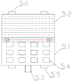
fig. 1 is a schematic structural diagram of the present invention;
FIG. 2 is a schematic structural view of the silicon wafer fixing device of the present invention;
in the figure: 1. a housing; 2. supporting legs; 3. an upper cover; 4. a stirring motor; 5. a silicon wafer fixing device; 5.1, a front splint; 5.2, a rear splint; 5.3, connecting columns; 5.4, a clamping groove; 5.5, locking lugs; 5.6, locking; 6. an electric heater; 7. an ultrasonic generator; 8. a water inlet pipe; 9. an exhaust pipe; 10. a drain pipe; 11. an exhaust gas treatment device; 11.1, a liquid storage tank; 11.2, spraying an absorption tower; 11.3, an air inlet chamber; 11.4, gas-liquid contact packing layer; 11.5, a spraying layer; 11.6, a cyclone demisting plate; 11.7, demisting a filler layer; 11.8, a wire mesh defogging layer; 11.9, an air inlet; 11.10, emptying the pipe; 11.11, an absorption liquid spray head; 11.12, a circulating pump; 12. a liquid level meter; 13. a handle.
Detailed Description
The technical solution for achieving the objectives of the present invention will be further described by using several specific examples, and it should be noted that the technical solution claimed in the present invention includes, but is not limited to, the following examples.
Example 1
As a most basic embodiment of the present invention, the present embodiment discloses an environment-friendly silicon wafer cleaning machine, as shown in fig. 1 and fig. 2, including a housing 1, a supporting leg 2 and an upper cover 3, the upper cover 3 is disposed on the upper end of the housing 1, the supporting leg 2 is fixedly disposed on the lower end of the housing 1, the bottom end of the housing 1 is fixedly provided with a stirring motor 4, the output end of the stirring motor 4 penetrates through the housing 1 to the inside of the housing 1, and the output end is connected to a silicon wafer fixing device 5, the silicon wafer fixing device 5 includes a front clamping plate 5.1, a rear clamping plate 5.2, a connecting column 5.3, a clamping groove 5.4, a locking lug 5.5 and a lock catch 5.6, the front clamping plate 5.1 is hinged to the rear clamping plate 5.2, and the size of the front clamping plate 5.1 is the; the lock lugs 5.5 are welded on two sides of the front clamping plate 5.1; the lock catches 5.6 are welded on two sides of the rear clamping plate 5.2 and matched with the lock lugs 5.5; the connecting column 5.3 is welded in the middle of the front clamping plate 5.1; a plurality of clamping grooves 5.4 are welded on the rear side of the front clamping plate 5.1 and matched with the silicon wafer in size; front splint 5.1 and back splint 5.2 all adopt hollow out construction, 1 inner wall of casing is fixed all around and is provided with electric heater 6, 1 inner wall bottom of casing is fixed and is provided with supersonic generator 7, 1 lateral wall upper end of casing is provided with inlet tube 8, the filler pipe still is provided with blast pipe 9 to on the opposite casing 1, blast pipe 9 links to each other with exhaust treatment device 11, 1 lateral wall lower extreme of casing is provided with drain pipe 10.
The utility model provides a pair of environment-friendly silicon chip cleaning machine, take off silicon chip fixing device 5 during the use, place the silicon chip on draw-in groove 5.4, it is fixed well with front splint 5.1 and back splint 5.2 through lock ear 5.5 and hasp 5.6, link to each other spliced pole 5.3 and agitator motor 4's output shaft afterwards, flow in the washing liquid from inlet tube 8, then open electric heater 6, supersonic generator 7 and agitator motor 4, agitator motor 4 stirs and 7 work of supersonic generator drive washing pond washing liquid production vibrations in, clean the silicon chip simultaneously, make silicon chip cleaning efficiency higher, the organic waste gas that produces in the cleaning process discharges waste gas treatment device 11 from blast pipe 9, exhaust gas treatment device 11 discharges the atmosphere after will containing organic waste gas's the gas treatment, environmental protection more. The used cleaning liquid is discharged from the apparatus through the drain pipe 10. The utility model has the advantages of simple structure, convenient operation are swift, the cleaning efficiency is high and environmental protection more.
Example 2
As a preferred embodiment of the present invention, the present embodiment discloses an environment-friendly silicon wafer cleaning machine, as shown in fig. 1 and fig. 2, including a housing 1, a supporting leg 2 and an upper cover 3, the upper cover 3 is disposed on the upper end of the housing 1, the supporting leg 2 is fixedly disposed at the lower end of the housing 1, the bottom end of the housing 1 is fixedly provided with a stirring motor 4, the output end of the stirring motor 4 penetrates through the interior of the housing 1 to the housing 1, and the output end is connected to a silicon wafer fixing device 5, the silicon wafer fixing device 5 includes a front clamping plate 5.1, a rear clamping plate 5.2, a connecting column 5.3, a clamping groove 5.4, a locking lug 5.5 and a lock catch 5.6, the front clamping plate 5.1 is hinged to the rear clamping plate 5.2, and the size of the front clamping plate 5.1 is the; the lock lugs 5.5 are welded on two sides of the front clamping plate 5.1; the lock catches 5.6 are welded on two sides of the rear clamping plate 5.2 and matched with the lock lugs 5.5; the connecting column 5.3 is welded in the middle of the front clamping plate 5.1; a plurality of clamping grooves 5.4 are welded on the rear side of the front clamping plate 5.1 and matched with the silicon wafer in size; front splint 5.1 and back splint 5.2 all adopt hollow out construction, 1 inner wall of casing is fixed all around and is provided with electric heater 6, 1 inner wall bottom of casing is fixed and is provided with supersonic generator 7, 1 lateral wall upper end of casing is provided with inlet tube 8, the filler pipe still is provided with blast pipe 9 to on the opposite casing 1, blast pipe 9 links to each other with exhaust treatment device 11, 1 lateral wall lower extreme of casing is provided with drain pipe 10.
Preferably, the waste gas treatment device 11 comprises a liquid storage tank 11.1 at the lower part and a spray absorption tower 11.2 at the upper part, absorption liquid is contained in the liquid storage tank 11.1, the liquid storage tank 11.1 is communicated with the inside of the spray absorption tower 11.2, the spray absorption tower 11.2 sequentially comprises an air inlet chamber 11.3, a gas-liquid contact packing layer 11.4, a spray layer 11.5, a rotational flow demisting plate 11.6, a demisting packing layer 11.7 and a silk screen demisting layer 11.8 from bottom to top, one side of the air inlet chamber 11.3 is provided with an air inlet 11.9, the air inlet 11.9 is connected with an exhaust pipe 9, the top of the spray absorption tower 11.2 is provided with an emptying pipe 11.10, the upper part of the spray layer 11.5 is provided with an absorption liquid spray head 11.11, and the absorption liquid in the liquid storage tank 11.1 is conveyed to the absorption liquid spray head 11.11 by a circulating pump 11.
Preferably, the filler filled in the gas-liquid contact filler layer 11.4 and the demisting filler layer 11.7 is a multi-surface hollow sphere made of polyethylene.
Preferably, the filler filled in the wire mesh defogging layer 11.8 is a stainless wire mesh or an aluminum alloy wire mesh.
Preferably, a liquid level meter 12 is arranged on the inner wall of the shell 1 below the exhaust pipe 9.
Preferably, the connecting column 5.3 is internally provided with an external thread.
Preferably, the output end of the stirring motor 4 is provided with an external thread matched with the internal thread of the connecting column 5.3.
Preferably, the upper cover 3 is provided with a handle 13.
The utility model provides a pair of environment-friendly silicon chip cleaning machine, take off silicon chip fixing device 5 during the use, place the silicon chip on draw-in groove 5.4, it is fixed well with front splint 5.1 and back splint 5.2 through lock ear 5.5 and hasp 5.6, link to each other spliced pole 5.3 and agitator motor 4's output shaft afterwards, flow in the washing liquid from inlet tube 8, then open electric heater 6, supersonic generator 7 and agitator motor 4, agitator motor 4 stirs and 7 work of supersonic generator drive washing pond washing liquid production vibrations in, clean the silicon chip simultaneously, make silicon chip cleaning efficiency higher, the organic waste gas that produces in the cleaning process discharges waste gas treatment device 11 from blast pipe 9, exhaust gas treatment device 11 discharges the atmosphere after will containing organic waste gas's the gas treatment, environmental protection more. The used cleaning liquid is discharged from the apparatus through the drain pipe 10. The utility model has the advantages of simple structure, convenient operation are swift, the cleaning efficiency is high and environmental protection more.
The spraying absorption tower 11.2 is specially used for absorbing the organic solvent in the waste gas, so that the majority of the organic solvent can be absorbed by more than 90%, the absorption effect is good, and the harm of the organic solvent in the waste gas to human bodies and the atmosphere is effectively reduced; by adopting the three-layer demisting structure, the loss of fog drops of the absorption liquid can be effectively prevented, and the occurrence of secondary pollution caused in the atmosphere in the diffusion of the absorption liquid is avoided. The filler of gas-liquid contact packing layer 11.4 and defogging packing layer 11.7 intussuseption is the multiaspect hollow sphere that the polyethylene made, and the filler of silk screen defogging layer 11.8 intussuseption is stainless steel net or aluminum alloy wire net for exhaust-gas treatment is more high-efficient, and multiaspect hollow sphere, stainless steel net and aluminum alloy wire net life are longer simultaneously. The use of the level gauge 12 monitors the cleaning liquid level in the housing 1 at any time, preventing the cleaning liquid from entering the exhaust gas treatment device 11. The use of external screw thread and internal thread for it is simpler that spliced pole 5.3 links to each other with agitator motor 4's output, makes things convenient for silicon chip fixing device 5 to take off and install, makes the operation simpler. The handle 13 is provided to facilitate opening of the upper lid 3.
The above-mentioned embodiments further describe in detail the objects, technical solutions and advantages of the present invention, it should be understood that the above only is the embodiments of the present invention, and is not intended to limit the present invention, any modification, equivalent replacement, improvement, etc. made within the spirit and principle of the present invention should be included within the protection scope of the present invention.
Claims (8)
1. The utility model provides an environment-friendly silicon chip cleaning machine, includes casing (1), supporting legs (2) and upper cover (3), and upper cover (3) set up in casing (1) upper end, and supporting legs (2) are fixed to be set up at casing (1) lower extreme, its characterized in that: the silicon wafer fixing device is characterized in that a stirring motor (4) is fixedly arranged at the bottom end of the shell (1), the output end of the stirring motor (4) penetrates through the shell (1) to the inside of the shell (1), the output end of the stirring motor is connected with the silicon wafer fixing device (5), the silicon wafer fixing device (5) comprises a front clamping plate (5.1), a rear clamping plate (5.2), a connecting column (5.3), a clamping groove (5.4), a locking lug (5.5) and a lock catch (5.6), the front clamping plate (5.1) is hinged with the rear clamping plate (5.2), and the size of the front clamping plate (5.1) is the same as that of the rear clamping plate (5.2; the lock lugs (5.5) are welded on two sides of the front clamping plate (5.1); the lock catches (5.6) are welded on two sides of the rear clamping plate (5.2) and are matched with the lock lugs (5.5); the connecting column (5.3) rod is welded in the middle of the front clamping plate (5.1); a plurality of clamping grooves (5.4) are welded on the rear side of the front clamping plate (5.1) and are matched with the silicon wafer in size; front splint (5.1) and back splint (5.2) all adopt hollow out construction, casing (1) inner wall is fixed all around and is provided with electric heater (6), casing (1) inner wall bottom is fixed and is provided with supersonic generator (7), casing (1) lateral wall upper end is provided with inlet tube (8), inlet tube (8) still are provided with blast pipe (9) to on opposite casing (1), blast pipe (9) link to each other with exhaust treatment device (11), casing (1) lateral wall lower extreme is provided with drain pipe (10).
2. The environment-friendly silicon wafer cleaning machine as claimed in claim 1, wherein: the waste gas treatment device (11) comprises a liquid storage tank (11.1) at the lower part and a spray absorption tower (11.2) at the upper part, the liquid storage tank (11.1) is filled with absorption liquid, the liquid storage tank (11.1) is communicated with the interior of the spray absorption tower (11.2), the spray absorption tower (11.2) is provided with an air inlet chamber (11.3), a gas-liquid contact packing layer (11.4), a spray layer (11.5), a rotational flow demisting plate (11.6), a demisting packing layer (11.7) and a wire mesh demisting layer (11.8) from bottom to top in sequence, an air inlet (11.9) is arranged on one side of the air inlet chamber (11.3), the air inlet (11.9) is connected with an exhaust pipe (9), the top of the spray absorption tower (11.2) is provided with an emptying pipe (11.10), the upper part of the spray layer (11.5) is provided with an absorption liquid spray head (11.11), and the absorption liquid in the liquid storage tank (11.1) is conveyed to an absorption liquid spray head (11.11) through a circulating pump (11.12).
3. The environment-friendly silicon wafer cleaning machine as claimed in claim 2, wherein: the filler filled in the gas-liquid contact filler layer (11.4) and the demisting filler layer (11.7) is a multi-surface hollow sphere made of polyethylene.
4. The environment-friendly silicon wafer cleaning machine as claimed in claim 2, wherein: the filler filled in the wire mesh defogging layer (11.8) is a stainless steel wire mesh or an aluminum alloy wire mesh.
5. The environment-friendly silicon wafer cleaning machine as claimed in claim 1, wherein: and a liquid level meter (12) is arranged on the inner wall of the shell (1) below the exhaust pipe (9).
6. The environment-friendly silicon wafer cleaning machine as claimed in claim 1, wherein: and an external thread is arranged inside the connecting column (5.3).
7. The environment-friendly silicon wafer cleaning machine as claimed in claim 6, wherein: and the output end of the stirring motor (4) is provided with an external thread matched with the internal thread of the connecting column (5.3).
8. The environment-friendly silicon wafer cleaning machine as claimed in claim 1, wherein: the upper cover (3) is provided with a handle (13).
Priority Applications (1)
| Application Number | Priority Date | Filing Date | Title |
|---|---|---|---|
| CN201921911010.5U CN211071092U (en) | 2019-11-07 | 2019-11-07 | Environment-friendly silicon wafer cleaning machine |
Applications Claiming Priority (1)
| Application Number | Priority Date | Filing Date | Title |
|---|---|---|---|
| CN201921911010.5U CN211071092U (en) | 2019-11-07 | 2019-11-07 | Environment-friendly silicon wafer cleaning machine |
Publications (1)
| Publication Number | Publication Date |
|---|---|
| CN211071092U true CN211071092U (en) | 2020-07-24 |
Family
ID=71622113
Family Applications (1)
| Application Number | Title | Priority Date | Filing Date |
|---|---|---|---|
| CN201921911010.5U Active CN211071092U (en) | 2019-11-07 | 2019-11-07 | Environment-friendly silicon wafer cleaning machine |
Country Status (1)
| Country | Link |
|---|---|
| CN (1) | CN211071092U (en) |
Cited By (3)
| Publication number | Priority date | Publication date | Assignee | Title |
|---|---|---|---|---|
| CN112024522A (en) * | 2020-08-17 | 2020-12-04 | 江苏弘扬石英制品有限公司 | Cleaning machine for quartz glass tube |
| CN112427392A (en) * | 2020-12-08 | 2021-03-02 | 江西舜源电子科技有限公司 | Be used for abluent basket of flowers of silicon chip to rock device |
| CN114210636A (en) * | 2021-12-06 | 2022-03-22 | 杭州中欣晶圆半导体股份有限公司 | Etching device and method for improving etching rate of silicon chip oxide film |
-
2019
- 2019-11-07 CN CN201921911010.5U patent/CN211071092U/en active Active
Cited By (3)
| Publication number | Priority date | Publication date | Assignee | Title |
|---|---|---|---|---|
| CN112024522A (en) * | 2020-08-17 | 2020-12-04 | 江苏弘扬石英制品有限公司 | Cleaning machine for quartz glass tube |
| CN112427392A (en) * | 2020-12-08 | 2021-03-02 | 江西舜源电子科技有限公司 | Be used for abluent basket of flowers of silicon chip to rock device |
| CN114210636A (en) * | 2021-12-06 | 2022-03-22 | 杭州中欣晶圆半导体股份有限公司 | Etching device and method for improving etching rate of silicon chip oxide film |
Similar Documents
| Publication | Publication Date | Title |
|---|---|---|
| CN211071092U (en) | Environment-friendly silicon wafer cleaning machine | |
| CN206794265U (en) | A kind of cleaning device for cleaning large scale quartz wafer | |
| CN104707821A (en) | Energy-saving type medical equipment cleaning and sterilization device | |
| CN207119577U (en) | A kind of swing medical instrument cleaning device | |
| CN101386009B (en) | Cleaning device | |
| CN209749755U (en) | strawberry belt cleaning device | |
| CN209420862U (en) | A kind of longitudinal cyclone formula sterilized food clearing machine of multistage filtering | |
| CN207238704U (en) | A kind of brewing rushes bottle integration apparatus with wash bottle | |
| CN208274046U (en) | A kind of efficient pyrus nivalis cleaning equipment | |
| CN211563892U (en) | Cosmetic bottle cleaning equipment | |
| CN209515213U (en) | A kind of decontamination plant for nuclear power station radioactive pollution | |
| CN214638877U (en) | Chemical container cleaning device | |
| CN110479688B (en) | Rotary pickling device for cyclic utilization of pickling solution for silicon wafer production | |
| CN208213780U (en) | A kind of efficient aquatic product cleaning tank | |
| CN210386740U (en) | Cleaning device convenient to wash prism | |
| CN210474893U (en) | Chemical box | |
| CN210675143U (en) | Reation kettle cleaning device is used in production of vegetable oil polyether defoaming agent | |
| CN208974175U (en) | A kind of cleaning device of dental aligners | |
| CN208495099U (en) | A kind of Multifunctional medical instrument cleaning device | |
| CN218486694U (en) | Scrubbing machine for removing mineral impurities | |
| CN216369295U (en) | Novel bearing cleaning device | |
| CN206273398U (en) | A kind of medicine equipment cleans basket | |
| CN213701115U (en) | Automatic cleaning device for chemical experiment apparatus | |
| CN215314556U (en) | Liquefied petroleum gas storage tank surface greasy dirt cleaning device | |
| CN218873044U (en) | Medical instrument belt cleaning device |
Legal Events
| Date | Code | Title | Description |
|---|---|---|---|
| GR01 | Patent grant | ||
| GR01 | Patent grant |