CN211036715U - Folding connecting device for lower guide beam supporting legs of bridge girder erection machine - Google Patents
Folding connecting device for lower guide beam supporting legs of bridge girder erection machine Download PDFInfo
- Publication number
- CN211036715U CN211036715U CN201921765328.7U CN201921765328U CN211036715U CN 211036715 U CN211036715 U CN 211036715U CN 201921765328 U CN201921765328 U CN 201921765328U CN 211036715 U CN211036715 U CN 211036715U
- Authority
- CN
- China
- Prior art keywords
- connecting seat
- guide beam
- plate
- lower guide
- bridge girder
- Prior art date
- Legal status (The legal status is an assumption and is not a legal conclusion. Google has not performed a legal analysis and makes no representation as to the accuracy of the status listed.)
- Active
Links
Images


Abstract
The utility model discloses a folding connecting device for lower guide beam support legs of a bridge girder erection machine, which is used for being connected with the lower guide beam when folding the lower guide beam support legs, and comprises an upper connecting seat, a lower connecting seat and a connecting bolt, wherein the upper connecting seat is arranged on the lower guide beam, the lower connecting seat is arranged on the support legs, and the upper connecting seat and the lower connecting seat are connected through the connecting bolt, the support legs are changed into a horizontal folding state from a vertical state, and can move together with the bridge girder erection machine, the existing mode of detaching the support legs and transporting the support legs independently is replaced, and the equipment investment is saved; the lower connecting seat is provided with two fixing bolts, so that the positioning is convenient, the fixed spacing position of the lower ear plate is ensured, and the butt joint with the upper ear plate is convenient; the upper connecting seat is of a single-body structure, the adjusting space is large, and collision deformation during butt joint is reduced through rotation adjustment during butt joint. The utility model has the advantages of simple structure, the preparation is convenient, effectively reduces construction cost and promotes the efficiency of construction.
Description
Technical Field
The utility model relates to a bridge construction technical field, concretely relates to nose girder landing leg folding joint device under frame bridge crane.
Background
When carrying out bridge construction, generally need adopt the bridging machine to carry out the construction, the bridging machine shifts or when crossing the continuous beam between the bridge, need dismantle the nose girder landing leg and transport alone and shift down, wastes time and energy, not only needs to use tools such as crane and large-scale flatbed, increases construction cost, and the jack-up hoist and mount has certain potential safety hazard moreover. The utility model provides a nose girder landing leg folding joint device overcomes above-mentioned defect under frame bridge crane.
SUMMERY OF THE UTILITY MODEL
The utility model provides a nose girder landing leg folding joint device under frame bridge crane articulates on frame bridge crane through this device after folding with the landing leg, reduces the transportation equipment and uses, reduces construction cost.
The utility model provides a technical scheme that above-mentioned technical problem adopted is:
A folding connecting device for lower guide beam and support legs of a bridge girder erection machine is used for connecting the support legs with the lower guide beam of the bridge girder erection machine when the support legs are folded and comprises an upper connecting seat, a lower connecting seat and connecting bolts, wherein the upper connecting seat is arranged on the lower guide beam, the lower connecting seat is arranged on the support legs, and the lower connecting seat is connected with two upper connecting seats through the connecting bolts;
The upper connecting seat comprises an upper connecting plate, an upper lug plate and a fixing bolt; the upper ear plate and the fixing bolt are respectively vertically arranged at the upper side and the lower side of the upper connecting plate, and the fixing bolt is fixed in the through hole on the lower guide beam;
The lower connecting seat comprises a lower connecting plate, a lower lug plate and a fixing bolt; the lower ear plates and the fixing bolts are respectively vertically arranged on the upper side and the lower side of the lower connecting plate, the lower ear plates are provided with two pairs, each pair of lower ear plates comprises two parallel ear plates, the upper ear plate is positioned between the two lower ear plates and is connected through the connecting bolt, and the two fixing bolts are positioned in through holes on the supporting legs.
Furthermore, an upper fixing gasket is arranged on the upper connecting seat, is arranged on a fixing bolt of the upper connecting seat and is positioned on the back of the connecting plate on the lower guide beam;
And the lower connecting seat is provided with a lower fixing gasket, and the lower fixing gasket is arranged on two fixing bolts of the lower connecting seat and is positioned on the back of the connecting plate of the supporting leg.
Furthermore, the outer ends of the upper lug plate and the lower lug plate are semicircular, through holes are formed in the circle centers of the upper lug plate and the lower lug plate, and the connecting bolt is located in the through holes.
Furthermore, the upper connecting plate, the upper lug plate and the fixing bolt are connected through welding to form an upper connecting seat; the lower connecting plate, the lower lug plate and the fixing bolt are connected through welding to form a lower connecting seat.
Further, the distance between the two pairs of lower ear plates is the same as that between the through holes in the connecting plate of the supporting leg.
Further, upper junction plate, upper ear board, lower connecting plate and lower ear board are the Q345 steel sheet of 30mm thick, it is the Q345 steel sheet of 20mm thick with lower fixed shim to go up fixed shim, the gim peg is M24 screw rod, the gim peg is M24 bolt.
The utility model discloses beneficial effect as follows:
The support legs are folded and connected to the lower guide beam and transported along with the bridge girder erection machine, and the support legs are not transported independently, so that equipment investment is saved;
The lower connecting seat is provided with two fixing bolts, so that the positioning is convenient, the fixed spacing position of the lower ear plate is ensured, and the butt joint with the upper ear plate is convenient; the upper connecting seat is of a single-body structure, the adjusting space is large, and collision deformation during butt joint is reduced by rotating and adjusting during butt joint;
The utility model discloses simple structure, the preparation is convenient, effectively reduces construction cost, promotes the efficiency of construction.
Drawings
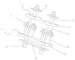
FIG. 1 is a schematic view of the usage state of the present invention;
FIG. 2 is a schematic view of the overall structure of the present invention;
Fig. 3 is a schematic view of the structure of the lower connecting seat of the present invention.
Reference numerals: 1-upper connecting seat, 11-upper connecting plate, 12-upper lug plate, 13-fixing bolt, 14-upper fixing gasket, 2-lower connecting seat, 21-lower connecting plate, 22-lower lug plate, 23-lower fixing gasket and 3-connecting bolt.
Detailed Description
The technical solutions in the embodiments of the present invention will be described clearly and completely with reference to the accompanying drawings, and obviously, the described embodiments are only some embodiments, not all embodiments, of the present invention. Based on the embodiments in the present invention, all other embodiments obtained by a person skilled in the art without creative work belong to the protection scope of the present invention.
In the description of this patent, it is to be understood that the terms "center," "upper," "lower," "front," "rear," "left," "right," "vertical," "horizontal," "top," "bottom," "inner," "outer," and the like are used in the orientations and positional relationships indicated in the drawings for the convenience of describing the patent and for the simplicity of description, and are not intended to indicate or imply that the referenced devices or elements must have a particular orientation, be constructed and operated in a particular orientation, and are not to be considered limiting of the patent.
As shown in fig. 1, 2 and 3, the folding connecting device for the lower guide beam support leg of the bridge girder erection machine is used for connecting the lower guide beam support leg of the bridge girder erection machine when the lower guide beam support leg is folded, and comprises an upper connecting seat 1, a lower connecting seat 2 and connecting bolts 3, wherein the upper connecting seat 1 is arranged on the lower guide beam, the lower connecting seat 2 is arranged on the support leg, and the lower connecting seat 2 is connected with the two upper connecting seats 1 through the connecting bolts 3;
The upper connecting seat 1 comprises an upper connecting plate 11, an upper lug plate 12 and a fixing bolt 13; the upper ear plate 12 and the fixing bolt 13 are respectively vertically arranged at the upper side and the lower side of the upper connecting plate 11, and the fixing bolt 13 is fixed in a through hole on the lower guide beam;
The lower connecting seat 2 comprises a lower connecting plate 21, a lower lug plate 22 and a fixing bolt 13; the lower ear plates 22 and the fixing bolts 13 are respectively vertically arranged on the upper side and the lower side of the lower connecting plate 21, the lower ear plates 22 are arranged in two pairs, each pair of lower ear plates 22 comprises two parallel ear plates, the upper ear plate 12 is positioned between the two lower ear plates 22 and is connected through the connecting bolts 3, and the fixing bolts 13 are arranged in two through holes in the supporting legs.
Preferably, the two devices are respectively positioned at the upper parts of the two sides of the connecting position; the upper connecting seat 1 and the lower connecting seat 2 are arranged on the lower guide beam and the supporting leg through fixing bolts 13 and are fastened through nuts arranged on the outer sides of the gaskets.
The utility model discloses utilize the connecting hole between nose girder and the landing leg under the current bridge girder erection machine, through this device with the landing leg folding back fixed under on the nose girder, together remove at bridge girder erection machine, guarantee the efficiency of construction, reduce construction cost.
As shown in fig. 2 and 3, further, an upper fixing gasket 14 is arranged on the upper connecting seat 1, and the upper fixing gasket 14 is arranged on a fixing bolt 13 of the upper connecting seat 1 and is located on the back of the connecting plate on the lower guide beam;
And a lower fixing gasket 23 is arranged on the lower connecting seat 2, and the lower fixing gasket 23 is arranged on the two fixing bolts 13 of the lower connecting seat 2 and is positioned on the back of the connecting plate of the supporting leg. The lower fixing gasket 23 is arranged to be integrated, the number of components is reduced, and the installation is more convenient.
As shown in fig. 2, further, the outer ends of the upper ear plate 12 and the lower ear plate 22 are semicircular, and the centers of the two ends are provided with through holes, and the connecting bolt 3 is located in the through holes.
Further, the upper connecting plate 11, the upper ear plate 12 and the fixing bolt 13 are connected by welding to form an upper connecting seat 1; the lower connecting plate 21, the lower ear plate 22 and the fixing bolt 13 are connected by welding to form the lower connecting seat 2.
Further, the distance between the two pairs of lower ear plates 22 is the same as the distance between the through holes on the connecting plate of the support leg.
Further, the upper connecting plate 11, the upper lug plate 12, the lower connecting plate 21 and the lower lug plate 22 are Q345 steel plates with the thickness of 30mm, the upper fixing gasket 14 and the lower fixing gasket 23 are Q345 steel plates with the thickness of 20mm, the fixing bolt 13 is an M24 screw, and the connecting bolt 3 is an M24 bolt.
The utility model discloses a concrete application method as follows:
Firstly, detaching a connecting bolt at the connecting position of a support leg and a lower guide beam, detaching the support leg, and lifting the lower guide beam by 30 cm;
Secondly, preassembling the upper connecting seat 1 onto the lower guide beam, fixing the lower connecting seat 2 on the supporting legs, then lowering the lower guide beam, butting the upper connecting seat 1 and the lower connecting seat 2, adjusting the angle of the upper connecting seat 1 in the butting process to facilitate accurate butting, and after the butting is finished, connecting and fastening the upper connecting seat 1 and the lower connecting seat 2 through the connecting bolt 3, and fixing the upper connecting seat 1 and the lower guide beam firmly;
And thirdly, folding the supporting legs to be in a horizontal state, fixing the supporting legs, moving the supporting legs together with the bridge girder erection machine, dismounting the device after the supporting legs move in place, and restoring the supporting legs to be horizontal for construction.
It is obvious to a person skilled in the art that the invention is not restricted to details of the above-described exemplary embodiments, but that it can be implemented in other specific forms without departing from the spirit or essential characteristics of the invention. The present embodiments are therefore to be considered in all respects as illustrative and not restrictive, the scope of the invention being indicated by the appended claims rather than by the foregoing description, and all changes which come within the meaning and range of equivalency of the claims are therefore intended to be embraced therein, and any reference signs in the claims are not intended to be construed as limiting the claim concerned.
Claims (6)
1. A folding connecting device for supporting legs of a lower guide beam of a bridge girder erection machine is used for connecting the supporting legs with the lower guide beam of the bridge girder erection machine when the supporting legs are folded, and is characterized by comprising an upper connecting seat (1), a lower connecting seat (2) and connecting bolts (3), wherein the upper connecting seat (1) is arranged on the lower guide beam, the lower connecting seat (2) is arranged on the supporting legs, and the lower connecting seat (2) is connected with the two upper connecting seats (1) through the connecting bolts (3);
The upper connecting seat (1) comprises an upper connecting plate (11), an upper lug plate (12) and a fixing bolt (13); the upper ear plate (12) and the fixing bolt (13) are respectively vertically arranged at the upper side and the lower side of the upper connecting plate (11), and the fixing bolt (13) is fixed in a through hole on the lower guide beam;
The lower connecting seat (2) comprises a lower connecting plate (21), a lower lug plate (22) and a fixing bolt (13); lower otic placode (22) and gim peg (13) are established the upper and lower both sides of connecting plate (21) down respectively perpendicularly, lower otic placode (22) sets up two pairs, and every is two including parallel arrangement's lower otic placode (22), it is located between two lower otic placodes (22) to go up otic placode (12) to connect through connecting peg (3), gim peg (13) set up two, are located the through-hole on the landing leg.
2. The folding connecting device for the lower guide beam and the support leg of the bridge girder erection machine as claimed in claim 1, is characterized in that: an upper fixing gasket (14) is arranged on the upper connecting seat (1), and the upper fixing gasket (14) is arranged on a fixing bolt (13) of the upper connecting seat (1) and positioned on the back of a connecting plate on the lower guide beam;
And a lower fixing gasket (23) is arranged on the lower connecting seat (2), and the lower fixing gasket (23) is arranged on two fixing bolts (13) of the lower connecting seat (2) and is positioned on the back of the connecting plate of the supporting leg.
3. The folding connecting device for the lower guide beam and the support leg of the bridge girder erection machine as claimed in claim 1, is characterized in that: the outer ends of the upper lug plate (12) and the lower lug plate (22) are semicircular, through holes are formed in the circle centers of the upper lug plate and the lower lug plate, and the connecting bolt (3) is located in the through holes.
4. The folding connecting device for the lower guide beam and the support leg of the bridge girder erection machine as claimed in claim 1, is characterized in that: the upper connecting plate (11), the upper lug plate (12) and the fixing bolt (13) are connected through welding to form an upper connecting seat (1); the lower connecting plate (21), the lower lug plate (22) and the fixing bolt (13) are connected through welding to form a lower connecting seat (2).
5. The folding connecting device for the lower guide beam and the support leg of the bridge girder erection machine as claimed in claim 1, is characterized in that: the distance between the two pairs of lower ear plates (22) is the same as that between the through holes on the connecting plate of the supporting leg.
6. The folding connecting device for the lower guide beam and the support leg of the bridge girder erection machine as claimed in claim 2, is characterized in that: go up connecting plate (11), last otic placode (12), connecting plate (21) and lower otic placode (22) are the Q345 steel sheet that 30mm is thick, go up fixing shim (14) and lower fixing shim (23) and be the Q345 steel sheet that 20mm is thick, gim peg (13) are the M24 screw rod, gim peg (3) are the M24 bolt.
Priority Applications (1)
| Application Number | Priority Date | Filing Date | Title |
|---|---|---|---|
| CN201921765328.7U CN211036715U (en) | 2019-10-21 | 2019-10-21 | Folding connecting device for lower guide beam supporting legs of bridge girder erection machine |
Applications Claiming Priority (1)
| Application Number | Priority Date | Filing Date | Title |
|---|---|---|---|
| CN201921765328.7U CN211036715U (en) | 2019-10-21 | 2019-10-21 | Folding connecting device for lower guide beam supporting legs of bridge girder erection machine |
Publications (1)
| Publication Number | Publication Date |
|---|---|
| CN211036715U true CN211036715U (en) | 2020-07-17 |
Family
ID=71562479
Family Applications (1)
| Application Number | Title | Priority Date | Filing Date |
|---|---|---|---|
| CN201921765328.7U Active CN211036715U (en) | 2019-10-21 | 2019-10-21 | Folding connecting device for lower guide beam supporting legs of bridge girder erection machine |
Country Status (1)
| Country | Link |
|---|---|
| CN (1) | CN211036715U (en) |
-
2019
- 2019-10-21 CN CN201921765328.7U patent/CN211036715U/en active Active
Similar Documents
| Publication | Publication Date | Title |
|---|---|---|
| CN211036715U (en) | Folding connecting device for lower guide beam supporting legs of bridge girder erection machine | |
| CN211102435U (en) | Large-scale box girder welded platform | |
| CN205104195U (en) | Environmental protection profiled steel structure swiftly assembles single -upright -column bill -board | |
| CN216190654U (en) | Line-straight-down type station room finite space large-span steel structure lifting tool | |
| CN210032670U (en) | Mounting device for steel truss | |
| CN215443297U (en) | Special section bar for container | |
| CN214267774U (en) | Auxiliary frame assembly and concrete pump truck | |
| CN212313683U (en) | Semitrailer detachable platform | |
| CN209874185U (en) | A piece together formula angle steel lattice keel bearing structure for stone material curtain | |
| CN202706083U (en) | Bulldozer and bulldozer working device | |
| CN202848881U (en) | Space truss portal crane | |
| CN109083322A (en) | A kind of steel construction with curved support frame | |
| CN208117117U (en) | A kind of fixing tool guaranteeing the true flange welding size of supporting leg | |
| CN217711894U (en) | Supporting and connecting assembly | |
| CN110844804B (en) | Supporting construction method of ultra-long truss type tower crane attachment system | |
| CN216071094U (en) | Special transportation fixed bolster of gas turbine | |
| CN113756597B (en) | Quick-detachable steel structure mounting temporary support system and method | |
| CN213509741U (en) | Steel bar processing shed with single-side support | |
| CN214024246U (en) | Straight oblique web T type roof beam assembly fixture | |
| CN217362151U (en) | Frame fast assembly structure | |
| CN204751892U (en) | Rolling mill speed reducer special lifting device | |
| CN220598197U (en) | Hanging basket traction limiting device | |
| CN216380656U (en) | Steel construction bearing structure convenient to dismantle | |
| CN218287879U (en) | Combined air bag support for heavy-duty car | |
| CN215107513U (en) | Adjustable tripod for supporting overhanging floor bearing plate |
Legal Events
| Date | Code | Title | Description |
|---|---|---|---|
| GR01 | Patent grant | ||
| GR01 | Patent grant |