Novel waste water recycling system is handled to sediment water film
Technical Field
The utility model relates to an industrial wastewater treatment technical field, concretely relates to novel waste water recycling system is handled to sediment water film.
Background
At present, most domestic thermal power plants adopt a wet-type slag removal mode, the mode has the problems of high water consumption and large discharged sewage amount of a slag water treatment system, and the zero emission requirement of the thermal power plants is increasingly strict along with the increasing national pressure of energy conservation and emission reduction, so that the research and the improvement on the slag water system are carried out, the closed circulation of the slag water removal system is realized, and the zero emission is really urgent.
the ash and slag flushing water suspended matter content of the thermal power plant is high, under general conditions, the SS concentration after the overflow is precipitated through a dewatering bin or a slag conveyor is 2000-3000 mg/L, and a large amount of floating beads and floating ash which are not easy to precipitate are accompanied, so that for most of the coal-fired power plants in the country, the coal quality condition is worsened, the load of a slag water circulating system is increased, and the original slag water treatment facility cannot normally operate.
at present, the domestic slag water treatment method generally adopts a sedimentation tank, a thickener, a ceramic filter brick tank and other treatment methods, a few manufacturers also adopt a flocculation precipitation, inclined tube and sand filtration mode, the treatment technologies have various problems, the treatment technologies are also deficient in treatment capacity and operation stability and reliability, if the sedimentation tank is adopted, the removal rate of suspended matters is low, the quality of effluent water is poor, the occupied area is large, the cleaning tank is frequent and the workload is large, the thickener requires low content of suspended matters at the inlet and poor quality of effluent water, inclined tubes (plates) are easy to block and need manual cleaning, vertical tubes at an ash discharge port are easy to block, so that the sludge discharge is not smooth, pressure rake accidents and the like often occur, the biggest problems of the technologies are low impact load resistance, the tubular membranes can bear high concentration (2-5%) of suspended matters, particularly, the slag water with the occupation of more than 5000 mg/L can not be normally treated, the tubular membranes can not normally treat high suspended matters in high-suspended matters sewage, the novel automatic slag water treatment technology can realize SDI (SDI) filtration, and the high-concentration sewage treatment technology can be realized without adding flocculant, the novel high-load recycling technology, the novel high-load filtering technology can be used for high-load recycling and high-efficiency sewage treatment, the high-load-saving technology can be realized, the high-efficiency sewage treatment technology can be realized, the novel high-efficiency automatic sewage treatment technology is realized, the high-efficiency sewage treatment technology is realized by adding cost is realized, the novel high-efficiency automatic recycling technology, the high-saving technology, the high-efficiency sewage treatment technology is realized by adding flocculant addition high-efficiency and.
SUMMERY OF THE UTILITY MODEL
An object of the utility model is to provide a novel waste water recycling system is handled to sediment water film to the shock-resistant load who proposes in solving above-mentioned background art is high, and equipment operation is stable, and the treatment effect is good, efficient, and it is excellent to go out water quality of water, and waste water can realize resource utilization's problem.
In order to achieve the above object, the utility model provides a following technical scheme: a novel recycling system for waste water treated by a slag water film comprises a slag water collecting pool, a decanter, a track matched with a grab bucket machine, a circulating water tank, a tubular microfiltration membrane component and a water production pool, wherein the slag water collecting pool is connected with system incoming water through a pipeline; a sludge reflux pump is arranged between the circulating water tank and the slag water collecting tank, a chemical cleaning system is arranged between the tubular microfiltration membrane component and the slag water lift pump, and the bottom of the slag water collecting tank is provided with a 3 per mill gradient.
Further, the sediment water collecting pit sets up two check, be equipped with automatic valve on the pipeline between two check sediment water collecting pits and the system water, set up the ultrasonic wave level gauge on the sediment water collecting pit, automatic valve and ultrasonic wave level gauge interlock, automatic valve switching signal is through interlocking with sediment water collecting pit liquid level, low level valve is automatic to be opened, high level valve self-closing, the level gauge signal is interlocked with the automatic valve that intakes, the control water pool liquid level is within the prescribed range, when the condition that the liquid level is high or the liquid level is low appears, control system reports to the police.
Furthermore, the decanter comprises a short drainage pipe, a horizontal drainage pipe, a vertical drainage pipe, a water production pipe and an exhaust valve, wherein the short drainage pipe is inserted into the slag water collection pool and is connected with the horizontal drainage pipe, the horizontal drainage pipe is connected with the vertical drainage pipe, the vertical drainage pipe is connected with the water production pipe, the exhaust valve is arranged on the vertical drainage pipe, and the water production pipe is connected with the circulating water tank.
Further, chemical cleaning system includes that scavenging pump, acid solution wash case and sodium hypochlorite solution wash the case, and the import of scavenging pump washs the case with acid solution respectively and sodium hypochlorite solution washs the case and links to each other, and the scavenging pump export is passed through the pipe connection on the pipeline between sediment water elevator pump and tubular microfiltration membrane subassembly.
Further, the back flushing system comprises a back flushing water pump and a matched pipeline valve, when back flushing is carried out, the back flushing water pump pumps water in the water producing pool to flow to the tubular microfiltration membrane component, the tubular microfiltration membrane component is back flushed, the back flushing system is generally used for large flushing, the whole process system is required to stop running temporarily, as the structural improvement, the back flushing system can also be provided with small flushing, for example, the backflushing system also comprises a backflushing column for storing water, a backflushing compressed air pipeline and a water production pneumatic valve, the bottom of the backflushing column is connected with the top of the tubular microfiltration membrane component through a pipeline, the top of the backwashing column is connected with a water production pneumatic valve through a pipeline, the upper edge of the side part is sequentially connected with a manual valve, an electromagnetic valve and a check valve through pipelines, a switch on an electric control cabinet is opened, when water is produced in operation, a slag water lifting pump operates, the water production pneumatic valve is opened, and the electromagnetic valve is closed; when the slag water lift pump stops for a short time during backflushing, the water production pneumatic valve is closed, the electromagnetic valve is opened, the tubular microfiltration membrane assembly is backflushed automatically by utilizing compressed air and water stored in the backflushing column so as to recover the water permeability of the membrane surface, the slag water lift pump is opened after the backflushing is finished, a new water production process is started, and the operation of the whole process system is uninterrupted during small flushing.
Furthermore, the decanter is a siphon decanter which has the working principle that in the water inlet stage, the water level in the slag water collecting tank rises continuously, the water level in the short drain pipe also rises continuously, but due to the water sealing effect in the U-shaped pipe in the vertical drain pipe, air in the pipe is blocked and pressurized, when the water level in the slag water collecting tank reaches the highest designed water level, the water level in the short drain pipe also reaches the highest water level but is still lower than the bottom of the horizontal drain pipe, the potential difference between the horizontal drain pipe and the vertical drain pipe reaches the maximum, the blocked air pressure in the pipe enables the water level of the horizontal short pipe to be below the bottom of the horizontal drain pipe, so as to prevent water from flowing out of the tank and settling for a period of time, an air outlet valve at the upper part of the vertical drain pipe is opened, air in the pipe is pressed out, supernatant in the slag water collecting tank enters the horizontal drain pipe from the short drain pipe under, until reaching the lowest water level, when the drainage begins, the exhaust valve is closed, thus ensuring that the lowest water level can be reached through the siphon action when the water level in the pool is lower than the bottom of the drainage short pipe.
Furthermore, the circulating water tank is a carbon steel cylindrical water tank with a conical bottom, the return pipe is an inverted U-shaped pipe, and the vertical drainage pipe is a U-shaped pipe.
compared with the prior art, the utility model has the beneficial effects that the sludge is grabbed by the grab bucket machine and is naturally aired in an airing field, the sludge dewatering equipment and supporting facilities are reduced, the investment cost and the operating cost are saved, the secondary medicine adding of sludge treatment is also avoided, the aired slag has certain economic value, an acid solution cleaning box and a sodium hypochlorite solution cleaning box are arranged in the cleaning system, an acid medicament is added to remove the dirt such as hardness and the like accumulated on the surface of a membrane for metal, an organic matter and the like can be removed by adding the sodium hypochlorite medicament, the decanter is a siphon decanter, the siphon decanter can decant clear water from the static pool surface without stirring and precipitating, the water quality is ensured, after the filtering is carried out through the tubular micro-filtration membrane assembly 7, the suspended matters in the slag water are greatly reduced, the water quality suspended matter content can reach 5-10 mg/L, the impurity removal effect is good, the technical route of the utility model is used for treating the slag water, the equipment runs stably, the treatment effect is good, the efficiency is high-efficiency, the water quality is excellent, the waste water can be recycled, and particularly the high-concentration waste water treatment technology has.
Drawings
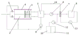
FIG. 1 is a general flow chart of a novel slag water film treatment wastewater recycling system of the utility model;
Fig. 2 is a schematic structural view of the decanter of the present invention.
In the figure: the system comprises a 1-automatic valve, a 2-slag water collecting tank, a 3-decanter, a 31-drainage short pipe, a 32-horizontal drainage pipe, a 33-drainage vertical pipe, a 34-water production pipe, a 35-exhaust valve, a 4-grab bucket machine matched rail, a 5-circulating water tank, a 14-backflow pipe, a 6-slag water lifting pump, a 7-tubular microfiltration membrane module, an 8-water production tank, a 9-sludge backflow pump, a 15-chemical cleaning system, a 10-acid solution cleaning tank, an 11-sodium hypochlorite solution cleaning tank, a 12-cleaning pump, a 16-backflushing system and a 13-backflushing water pump.
Detailed Description
The technical solutions in the embodiments of the present invention will be described clearly and completely with reference to the accompanying drawings in the embodiments of the present invention, and it is obvious that the described embodiments are only some embodiments of the present invention, not all embodiments. Based on the embodiments in the present invention, all other embodiments obtained by a person skilled in the art without creative work belong to the protection scope of the present invention.
the technical scheme includes that the novel slag water film treatment wastewater recycling system comprises a slag water collecting tank 2, a decanter 3, a grab machine matching track 4, a circulating water tank 5, a tubular microfiltration membrane component 7 and a production water tank 8, the slag water collecting tank 2 is connected with system incoming water through a pipeline, the decanter 3 is arranged in the slag water collecting tank 2, the grab machine matching track 4 is arranged on the slag water collecting tank 2, the circulating water tank 5 and the tubular microfiltration membrane component 7 are sequentially arranged from left to right between the slag water collecting tank 2 and the production water tank 8, the decanter 3 and the circulating water tank 5 are connected through a pipeline, a slag water lifting pump 6 is arranged between the circulating water tank 5 and the tubular microfiltration membrane component 7, a backflushing system 16 is arranged between the tubular microfiltration membrane component 7 and the production water tank 8, the tubular microfiltration membrane component 7 is connected with a current collection water tank 5 through a backflow pipe 14, the circulating water tank 5 and the backflow water collecting tank 2, the backflow tank 2 and the backwashing water tank 2 are connected with a backwashing water tank 5 through a backflow control system 7, a backwashing water tank 7 and a backwashing water tank 5, a backwashing water tank 7 and a wastewater collection tank 7 are connected with a sewage collection tank 5, a sewage collection tank 4, a sewage collection tank 7 and a sewage collection tank 2, a sewage collection tank 7 is arranged, a sewage collection tank 2, a sewage collection tank for sewage collection system for sewage collection, a sewage collection system for sewage collection, a sewage collection system for sewage collection, a sewage collection system for sewage collection, a sewage collection system for a sewage collection.
The slag water collecting tank 2 is provided with two grids, an automatic valve 1 is arranged on a pipeline between the slag water collecting tank 2 and system incoming water, the slag water collecting tank 2 is provided with an ultrasonic liquid level meter, the on-off signal of the automatic valve 1 is interlocked with the liquid level of the slag water collecting tank 2, the slag water collecting tank 2 is provided with two grids, the automatic valve 1 of the slag water collecting pool 2 selects the automatic valve, the switch signal of the automatic valve 1 is interlocked with the liquid level of the slag water collecting pool 2, the low liquid level valve is automatically opened, the high liquid level valve is automatically closed, the ultrasonic liquid level meter signal is interlocked with the automatic valve for water inlet to control the liquid level of the pool within the specified range, when the liquid level is high or low, the control system gives an alarm, and the ultrasonic liquid level meter is a liquid level meter with the model of HW-53B, for example, and has the characteristics of high precision, good quality and the like.
The decanter 3 comprises a drainage short pipe 31, a horizontal drainage pipe 32, a drainage vertical pipe 33, a water production pipe 34 and an exhaust valve 35, wherein the drainage short pipe 31 is inserted into the slag water collecting tank 2, the drainage short pipe 31 is connected with the horizontal drainage pipe 32, the horizontal drainage pipe 32 is connected with the drainage vertical pipe 33, the drainage vertical pipe 33 is connected with the water production pipe 34, the exhaust valve 35 is arranged on the drainage vertical pipe 33, the water production pipe 34 is connected with the circulating water tank 5, and when the drainage short pipe 31, the horizontal drainage pipe 32, the drainage vertical pipe 33, the water production pipe 34 and the exhaust valve 35 are connected, the interior is communicated.
The chemical cleaning system 15 comprises a cleaning pump 12, an acid solution cleaning tank 10 and a sodium hypochlorite solution cleaning tank 11, wherein the cleaning pump 12 is a pump with the model of 50FP-20, the inlet of the cleaning pump 12 is respectively connected with the acid solution cleaning tank 10 and the sodium hypochlorite solution cleaning tank 11, the outlet of the cleaning pump 12 is connected to a pipeline between the slag water lifting pump 6 and the tubular microfiltration membrane component 7 through a pipeline, an acid medicament is added to remove the dirt such as hardness and the like accumulated on the surface of the membrane for metal, and the sodium hypochlorite medicament is added to remove organic matters and the like.
The backflushing system 16 comprises a backflushing water pump 13 and a matched pipeline valve, and the backflushing water pump 13 is a water pump with the model number of 50WQ10-12-1.1QG, for example.
The decanter 3 is a siphon decanter which can decant clear water from the surface of the static tank without stirring and precipitating, so as to ensure the effect of the effluent water quality, and the decanter 3 is fixed on the concrete base of the slag water collecting tank 2, thereby being beneficial to the operation of the decanter 3.
The circulating water tank 5 is a carbon steel cylindrical water tank with a conical bottom, so that sludge discharge is facilitated, a sewage discharge outlet is formed in the bottom of the circulating water tank 5, an inlet of a slag water lifting pump 6 is formed in the lower edge of the side of the circulating water tank, and the sewage discharge outlet is connected with a sludge reflux pump 9 through a pipeline; the inlet of the slag water lift pump 6 is connected with the slag water lift pump 6 through a pipeline, the vertical drainage pipe 33 is a U-shaped pipe, the return pipe 14 is an inverted U-shaped pipe, and bubbles are prevented from being brought when the concentrated solution enters the tubular circulating water tank 5 through the return pipe 14.
As the structural improvement, each water tank and each water tank are provided with a liquid level meter with a remote transmission function, the interlocking with the pump can be realized through a liquid level signal, the starting and the stopping of the pump are controlled, and the liquid level control system is an ultrasonic liquid level meter, a pressure induction type liquid level meter, a magnetic turnover liquid level meter or a floating ball type liquid level switch.
A novel slag water film treatment process comprises the following steps: the system water is collected into a slag water collecting tank 2 through a pipeline, sludge precipitated in the slag water collecting tank 2 is grabbed to a drying field beside the tank through a track 4 matched with a grab bucket machine, supernatant in the slag water collecting tank 2 is decanted into a circulating water tank 5 through a decanter 3, the circulating water tank 5 lifts water to a tubular micro-filtration membrane component 7 through a slag water lifting pump 6, after the water is filtered through the tubular micro-filtration membrane component 7, water with greatly reduced suspended matters in the slag water enters a water production tank 8 for standby, the suspended solid concentration in the circulating water tank 5 can continuously rise along with the operation of the system, when the sludge reaches a certain concentration, the sludge is intermittently or continuously extracted through a sludge reflux pump 9 and is sent into the slag water collecting tank 2 for precipitation, and the sludge precipitated in the slag water collecting tank 2 is grabbed through the track 4 matched with the grab bucket machine.
The back flushing system 16 and the chemical cleaning system 15 carry out regular and irregular back flushing and chemical cleaning on the tubular micro-filtration membrane assembly 7, thereby keeping the stable and efficient work of the equipment.
The automatic valve 1, the slag water collecting tank 2, the short drainage pipe 31, the horizontal drainage pipe 32, the vertical drainage pipe 33, the water production pipe 34, the exhaust valve 35, the circulating water tank 5, the return pipe 14, the water production tank 8, the acid solution cleaning tank 10 and the sodium hypochlorite solution cleaning tank 11 are all made of stainless steel.
The working principle is as follows: a novel recycling system for waste water treated by slag water film comprises a slag water collecting pool 2, a decanter 3, a grab bucket machine matching track 4, a circulating water tank 5, a tubular micro-filtration membrane component 7 and a water producing pool 8, wherein system incoming water is collected into the slag water collecting pool 2 through a pipeline, sludge precipitated in the slag water collecting pool 2 is grabbed to a drying yard beside the pool through the grab bucket machine matching track 4, supernatant is decanted into the circulating water tank 5 through the decanter 3, the circulating water tank 5 lifts water to the tubular micro-filtration membrane component 7 through a slag water lifting pump 6, after being filtered through the tubular micro-filtration membrane component 7, water quality after suspended matters in the slag water are greatly reduced enters a water producing pool 8 for standby, the suspended solid concentration in the circulating water tank 5 can continuously rise along with the operation of the system, when the sludge reaches a certain concentration, the sludge is intermittently or continuously extracted through a sludge return pump 9, and (3) sending the sewage into a slag water collecting tank 2 for precipitation, descending the tubular microfiltration membrane component 7, and arranging a back flushing system 16 and a chemical cleaning system 15 in the system to carry out regular and irregular back flushing and chemical cleaning on the tubular microfiltration membrane component 7, so that the stable and efficient work of the equipment can be kept.
It is noted that, herein, relational terms such as first and second, and the like may be used solely to distinguish one entity or action from another entity or action without necessarily requiring or implying any actual such relationship or order between such entities or actions. Also, the terms "comprises," "comprising," or any other variation thereof, are intended to cover a non-exclusive inclusion, such that a process, method, article, or apparatus that comprises a list of elements does not include only those elements but may include other elements not expressly listed or inherent to such process, method, article, or apparatus.
Although embodiments of the present invention have been shown and described, it will be appreciated by those skilled in the art that changes, modifications, substitutions and alterations can be made in these embodiments without departing from the principles and spirit of the invention, the scope of which is defined in the appended claims and their equivalents.