CN211032915U - Double-power tricycle started by induction control - Google Patents
Double-power tricycle started by induction control Download PDFInfo
- Publication number
- CN211032915U CN211032915U CN201921887074.6U CN201921887074U CN211032915U CN 211032915 U CN211032915 U CN 211032915U CN 201921887074 U CN201921887074 U CN 201921887074U CN 211032915 U CN211032915 U CN 211032915U
- Authority
- CN
- China
- Prior art keywords
- tricycle
- rear axle
- frame
- started
- controller
- Prior art date
- Legal status (The legal status is an assumption and is not a legal conclusion. Google has not performed a legal analysis and makes no representation as to the accuracy of the status listed.)
- Active
Links
Images


Classifications
-
- Y—GENERAL TAGGING OF NEW TECHNOLOGICAL DEVELOPMENTS; GENERAL TAGGING OF CROSS-SECTIONAL TECHNOLOGIES SPANNING OVER SEVERAL SECTIONS OF THE IPC; TECHNICAL SUBJECTS COVERED BY FORMER USPC CROSS-REFERENCE ART COLLECTIONS [XRACs] AND DIGESTS
- Y02—TECHNOLOGIES OR APPLICATIONS FOR MITIGATION OR ADAPTATION AGAINST CLIMATE CHANGE
- Y02T—CLIMATE CHANGE MITIGATION TECHNOLOGIES RELATED TO TRANSPORTATION
- Y02T10/00—Road transport of goods or passengers
- Y02T10/60—Other road transportation technologies with climate change mitigation effect
- Y02T10/70—Energy storage systems for electromobility, e.g. batteries
-
- Y—GENERAL TAGGING OF NEW TECHNOLOGICAL DEVELOPMENTS; GENERAL TAGGING OF CROSS-SECTIONAL TECHNOLOGIES SPANNING OVER SEVERAL SECTIONS OF THE IPC; TECHNICAL SUBJECTS COVERED BY FORMER USPC CROSS-REFERENCE ART COLLECTIONS [XRACs] AND DIGESTS
- Y02—TECHNOLOGIES OR APPLICATIONS FOR MITIGATION OR ADAPTATION AGAINST CLIMATE CHANGE
- Y02T—CLIMATE CHANGE MITIGATION TECHNOLOGIES RELATED TO TRANSPORTATION
- Y02T10/00—Road transport of goods or passengers
- Y02T10/60—Other road transportation technologies with climate change mitigation effect
- Y02T10/7072—Electromobility specific charging systems or methods for batteries, ultracapacitors, supercapacitors or double-layer capacitors
-
- Y—GENERAL TAGGING OF NEW TECHNOLOGICAL DEVELOPMENTS; GENERAL TAGGING OF CROSS-SECTIONAL TECHNOLOGIES SPANNING OVER SEVERAL SECTIONS OF THE IPC; TECHNICAL SUBJECTS COVERED BY FORMER USPC CROSS-REFERENCE ART COLLECTIONS [XRACs] AND DIGESTS
- Y02—TECHNOLOGIES OR APPLICATIONS FOR MITIGATION OR ADAPTATION AGAINST CLIMATE CHANGE
- Y02T—CLIMATE CHANGE MITIGATION TECHNOLOGIES RELATED TO TRANSPORTATION
- Y02T90/00—Enabling technologies or technologies with a potential or indirect contribution to GHG emissions mitigation
- Y02T90/10—Technologies relating to charging of electric vehicles
- Y02T90/14—Plug-in electric vehicles
Abstract
The utility model discloses a double dynamical tricycle that adopts induction control to start, including frame (9), top cap (3) and the locomotive structure that is connected with frame (9), be provided with a seat bucket structure on frame (9), be provided with the rear axle structure at the rear portion of frame (9), be provided with front wheel (10) on the locomotive structure, be provided with pedal system (11) on frame (9), and pedal system (11) and rear axle structure move the cooperation, still be provided with on the rear axle structure with rear axle structure move the mechanical power system that cooperates, still be connected with control system on mechanical power system; the tricycle is designed in a double-power (manual power and mechanical power) mode, and the tricycle can utilize the manual power and the mechanical power at the same time, so that the adaptability of the whole tricycle is better.
Description
Technical Field
The utility model relates to a fields such as tricycle, new forms of energy technique, specific saying so, a double dynamical tricycle that adopts induction control to start.
Background
The tricycle is a vehicle formed by reforming a bicycle, can carry people and goods, is very popular in the 20 th century and the 30 th century, and then gradually replaces the position of a rickshaw. The tricycle is a combination of a rickshaw and a bicycle. The tricycle may be divided into a human tricycle, an electric tricycle, a child tricycle, a battery tricycle, etc.
The pedal tricycle is divided into front and back parts, and has front steering wheel, handlebar, bell, brake, pedal and saddle, and the back wheel is driven by chain to rotate. The rear part of the tricycle is mainly a carriage, and the carriage body is a wooden semicircular shape and can accommodate two persons side by side. A foldable rain-proof awning is arranged on the carriage, and a spring and two wheels are arranged below the foldable rain-proof awning. A wooden box is arranged under the seat and can be opened, and tools and sundries of the driver and the like are stored in the wooden box. The seat is provided with a cushion made of cloth and cotton wool, and a pedal is arranged below the seat. The front of the carriage is provided with a hook which can be used for hanging a rainproof door curtain, the rainproof door curtain is generally made of canvas or oilcloth, and the rainproof door curtain is changed into a cotton door curtain in winter to block wind and keep cold.
New Energy (NE): also known as unconventional energy sources. Refers to various forms of energy sources other than traditional energy sources. The energy to be popularized is energy which is just developed and utilized or is actively researched, such as solar energy, geothermal energy, wind energy, ocean energy, biomass energy, nuclear fusion energy and the like.
Solar energy generally refers to the radiant energy of sunlight. The main utilization forms of solar energy include three main modes of solar photothermal conversion, photoelectric conversion and photochemical conversion. Solar energy in a broad sense is a source of much energy on earth, such as wind energy, chemical energy, potential energy of water, etc. in the form of energy caused by or converted into solar energy. The method for utilizing solar energy mainly comprises the following steps: a solar cell converting energy contained in sunlight into electric energy by photoelectric conversion; the solar water heater heats water by using the heat of sunlight, and generates electricity by using the hot water. The solar energy is clean and environment-friendly, has no pollution, has high utilization value, and has no energy shortage, and various advantages determine the irreplaceable position in energy replacement.
Photovoltaic panel assemblies are electrical power generating devices that produce direct current electricity when exposed to sunlight and are comprised of thin solid photovoltaic cells made almost entirely of semiconductor materials such as silicon. Because there are no moving parts, it can be operated for a long time without causing any loss. Simple photovoltaic cells can provide energy for watches and computers, and more complex photovoltaic systems can illuminate houses and supply power to the grid. The photovoltaic panel assembly can be made in different shapes and the assembly can be connected to generate more electricity. Both rooftops and building surfaces utilize photovoltaic panels, even as part of a window, skylight, or shelter, which are commonly referred to as building-attached photovoltaic systems.
SUMMERY OF THE UTILITY MODEL
An object of the utility model is to provide an adopt double dynamical tricycle of induction control start, adopt double dynamical (manpower, mechanical power) mode and design, do to utilize mechanical power when utilizing the manpower for whole tricycle adaptability is more excellent.
The utility model discloses a following technical scheme realizes: the utility model provides an adopt double dynamical tricycle of induction control start, includes frame, top cap and the locomotive structure that is connected with the frame, is provided with seat bucket structure on the frame, is provided with the rear axle structure at the rear portion of frame, is provided with the front wheel at the locomotive structure, be provided with pedal system on the frame, and pedal system and rear axle structure move the cooperation, at the structural mechanical power system who moves the complex with the rear axle structure that still is provided with of rear axle, still be connected with control system on mechanical power system.
Further for realizing better the utility model discloses, adopt the following structure that sets up very much: the control system comprises a solar panel, an electric power storage system, a controller IC3, a rotating speed sensor IC4 and a DC-DC converter, wherein the electric power storage system is connected with the controller IC3 through a wiring board IC2, the controller IC3 and the wiring board IC2 are both connected with a mechanical power system, the solar panel is connected with a wiring board IC2 through the DC-DC converter, a starting switch is further arranged between any polarity output end of the DC-DC converter and the controller IC3, a power-off switch is connected between any same power polarity connecting end of the wiring board IC2 and the controller IC3 and an output power polarity end of the controller IC3, the rotating speed sensor IC4 is matched with the pedal system, and the rotating speed sensor IC4 is in communication connection with the controller IC 3.
Further for realizing better the utility model discloses, adopt the following structure that sets up very much: the electric power storage system comprises a battery, a patch panel IC1 and a main switch, wherein the battery is connected with a wiring board IC2 through the patch panel IC1, the main switch is arranged between the patch panel IC1 and the wiring board IC2, and a charging port is further arranged on the patch panel IC 1.
Further for realizing better the utility model discloses, adopt the following structure that sets up very much: the rear axle structure comprises two rear wheels and a rear axle, the rear axle is matched with the rear part of the frame, and the two rear wheels are arranged on a rear shaft of the rear axle.
Further for realizing better the utility model discloses, adopt the following structure that sets up very much: the mechanical power system comprises a motor arranged on the rear wheel, the motor is in transmission connection with the rear shaft, and the control system is connected with the motor.
Further for realizing better the utility model discloses, adopt the following structure that sets up very much: the number of the motors is 1, and the motors are in driving connection with any rear wheel.
Further for realizing better the utility model discloses, adopt the following structure that sets up very much: the seat barrel structure comprises a rear seat arranged above the rear axle structure, a middle iron flower is arranged at a driving position of the frame, a rear iron flower is arranged on the rear seat, the middle iron flower and the rear iron flower are connected with a top cover, and the top cover is connected with the vehicle head structure through a front gear.
Further for realizing better the utility model discloses, adopt the following structure that sets up very much: a placing box is also arranged at the driving position.
Further for realizing better the utility model discloses, adopt the following structure that sets up very much: and a semi-automatic roller shutter device is also arranged at the position of the vehicle door formed by the middle iron flower and the rear iron flower.
Further for realizing better the utility model discloses, adopt the following structure that sets up very much: the bicycle head structure comprises a front fork, a front wheel is matched on the front fork, and a front stopper is connected between the front fork and a top cover.
Compared with the prior art, the utility model, following advantage and beneficial effect have:
(1) After the control system starts to work, the Hall type rotating speed sensor (rotating speed sensor) starts to work, receives a rotating speed signal from the chain plate, a driver steps on a pedal plate of the pedal system, the rotating speed sensor outputs a signal to the controller, and the controller converts direct current of a power supply into three-phase electricity after calculation and transmits the three-phase electricity to the motor; the faster the pedal is stepped on, the faster the motor rotates. On one hand, a driver steps on a pedal and then drives the rear axle through the primary reduction box, so that the vehicle can easily run, and on the other hand, as long as the circuit is started, the power-assisted control part circuit starts to work without manual excessive force application.
(2) The utility model discloses the outage switch who sets up connects the battery and carries the positive pole for driving motor for the controller to lead to the battery negative pole. When the control system works and the vehicle uses the brake in the running process, the power-off switch is closed, so that the motor does not work due to the fact that the motor cannot be powered. The braking process is normal, and in addition, the motor can be used for feeding back and braking to assist the braking.
(3) The utility model discloses the solar panel that sets up can convert solar energy into electric energy and save in the battery to for the operation of whole car provides power, and when solar panel conversion power was not enough, can also carry out the electric power storage through charging to the battery, make it can use solar energy and conventional power supply to carry out two power supplies synthetically.
Drawings
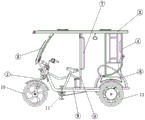
Fig. 1 is a schematic structural diagram of the present invention.
Fig. 2 is a single-side view of the present invention.
Fig. 3 is a top view of the present invention.
Fig. 4 is a schematic block diagram of the control system of the present invention.
Wherein the reference numerals are: 1-front fork, 2-front block, 3-top cover, 4-rear iron flower, 5-rear seat, 6-rear axle, 7-semi-automatic rolling device, 8-middle iron flower, 9-frame, 10-front wheel, 11-pedal system, 12-placing box, 13-rear wheel, 14-handlebar assembly, 15-motor and 16-rear shaft.
Detailed Description
The present invention will be described in further detail with reference to examples, but the present invention is not limited thereto.
To make the objects, technical solutions and advantages of the embodiments of the present invention clearer, the drawings of the embodiments of the present invention are combined to clearly and completely describe the technical solutions of the embodiments of the present invention, and obviously, the described embodiments are some embodiments of the present invention, not all embodiments. Based on the embodiments in the present invention, all other embodiments obtained by a person skilled in the art without creative work belong to the protection scope of the present invention. Thus, the following detailed description of the embodiments of the present invention, presented in the accompanying drawings, is not intended to limit the scope of the invention, as claimed, but is merely representative of selected embodiments of the invention. Based on the embodiments in the present invention, all other embodiments obtained by a person skilled in the art without creative work belong to the protection scope of the present invention.
In the description of the present invention, it is to be understood that the terms "center", "longitudinal", "lateral", "length", "width", "thickness", "upper", "lower", "front", "rear", "left", "right", "vertical", "horizontal", "top", "bottom", "inner", "outer", "clockwise", "counterclockwise", and the like indicate orientations or positional relationships based on the orientations or positional relationships shown in the drawings, and are only for convenience of description and to simplify the description, but do not indicate or imply that the device or element referred to must have a particular orientation, be constructed and operated in a particular orientation, and therefore should not be construed as limiting the present invention.
Furthermore, the terms "first", "second" and "first" are used for descriptive purposes only and are not to be construed as indicating or implying relative importance or implicitly indicating the number of technical features indicated. Thus, a feature defined as "first" or "second" may explicitly or implicitly include one or more of that feature. In the description of the present invention, "a plurality" means two or more unless specifically limited otherwise.
In the present invention, unless otherwise expressly stated or limited, the terms "mounted," "connected," and "fixed" are to be construed broadly and may, for example, be fixedly connected, detachably connected, or integrally formed; can be mechanically or electrically connected; either directly or indirectly through intervening media, either internally or in any other relationship. The specific meaning of the above terms in the present invention can be understood according to specific situations by those skilled in the art.
In the present disclosure, unless expressly stated or limited otherwise, the first feature "on" or "under" the second feature may comprise direct contact between the first and second features, or may comprise contact between the first and second features not directly. Also, the first feature being "on," "above" and "over" the second feature includes the first feature being directly on and obliquely above the second feature, or merely indicating that the first feature is at a higher level than the second feature. A first feature being "under," "below," and "beneath" a second feature includes the first feature being directly under and obliquely below the second feature, or simply meaning that the first feature is at a lesser elevation than the second feature.
Example 1:
The utility model relates to an adopt double dynamical tricycle of induction control start adopts double dynamical (manpower, mechanical power) mode and designs, does to utilize mechanical power when utilizing the manpower for whole tricycle adaptability is more excellent, as shown in fig. 1~4, adopts the following structure that sets up in particular: the bicycle comprises a frame 9, a top cover 3 and a bicycle head structure connected with the frame 9, wherein a seat barrel structure is arranged on the frame 9, a rear axle structure is arranged at the rear part of the frame 9, a front wheel 10 is arranged on the bicycle head structure, a pedal system 11 is arranged on the frame 9, the pedal system 11 is in actuating fit with the rear axle structure, a mechanical power system in actuating fit with the rear axle structure is also arranged on the rear axle structure, and a control system is also connected to the mechanical power system.
As a preferable arrangement scheme, the dual-power tricycle is provided with a frame 9, a top cover 3 is arranged on the frame 9, a head structure is further connected to the frame 9, a seat barrel structure is also arranged on the frame 9, a rear axle structure is arranged at the rear part of the frame 9, and a front wheel 10 is further arranged on the head structure; a pedal system mainly composed of pedals, chain wheels and chains is arranged on the frame 9, the pedal chain wheels are arranged at the driving part of the frame 9, and the chain wheels are in active fit with the rear axle structure through the chains; meanwhile, a mechanical power system is also arranged on the rear axle structure, the mechanical power system is in active fit with the rear axle structure and can drive a wheel assembly on the rear axle to run under the action of mechanical power, and a control system which is used for providing a power source for the mechanical power system and controlling the mechanical power system is also connected to the mechanical power system; the whole double-power tricycle can realize manual operation and also can realize mechanical power operation.
Example 2:
This embodiment is further optimized on the basis of above-mentioned embodiment, and the parts the same with aforementioned technical scheme will not be repeated herein again, as shown in fig. 1~4, further for better realizing the utility model discloses, adopt the following structure that sets up in particular: the control system comprises a solar panel, an electric power storage system, a controller IC3, a rotating speed sensor IC4 and a DC-DC converter, wherein the electric power storage system is connected with the controller IC3 through a wiring board IC2, the controller IC3 and the wiring board IC2 are both connected with a mechanical power system, the solar panel is connected with a wiring board IC2 through the DC-DC converter, a starting switch is further arranged between any polarity output end of the DC-DC converter and the controller IC3, a power-off switch is connected between any same power polarity connecting end of the wiring board IC2 and the controller IC3 and an output power polarity end of the controller IC3, the rotating speed sensor IC4 is matched with the pedal system, and the rotating speed sensor IC4 is in communication connection with the controller IC 3.
Preferably, the control system is mainly composed of a solar panel, an electric storage system, a controller IC3, a rotation speed sensor IC4, and a DC-DC converter. The power storage system is connected to the power supply inlet ends (input positive and negative ends) of the wiring board IC2, and the power supply outlet ends (output positive and negative ends) of the wiring board IC2 are connected to the power supply inlet ends (power input positive and negative ends) of the controller IC 3; the three-phase output end of the controller IC3 is connected to a mechanical power system (motor M) through a three-phase terminal of a wiring board IC2, the controller IC3 is also connected to the early mechanical power system (motor M), the solar panel is preferably arranged on the top cover 3 and is connected with a power supply inlet end (an input positive end and an input negative end) of a wiring board IC2 through a DC-DC converter, a protective tube is arranged on any connecting line between the DC-DC converter and the wiring board IC2 (preferably, the protective tube is arranged on a line between the positive output end of the DC-DC converter and an input positive end of the wiring board IC 2), and a node between the protective tube and the wiring board IC2 is connected to the output power supply positive end of the controller IC terminal 3 through a starting switch; further, a node is taken at any one of opposite polarities (preferably, both negative connection lines) of the power supply outlet terminal (the positive terminal and the negative terminal of the output) of the wiring board IC2 and the power supply inlet terminal (the positive terminal and the negative terminal of the power supply input) of the controller IC3 and is connected to the negative terminal of the output power supply of the controller IC3 through a power-off switch; the rotation speed sensor IC4 is arranged at a chain wheel of the pedal system through an auxiliary part and is used for sensing the rotation speed of the chain wheel, the rotation speed sensor IC4 is in communication connection with the controller IC3, the sensed rotation speed information can be fed back to the controller IC3 for further data processing, and preferably, the controller IC3 adopts the name red 181101521000w, and the DC-DC converter adopts HV 6008N.
Example 3:
This embodiment is further optimized on the basis of any above-mentioned embodiment, and the parts the same with aforementioned technical scheme will not be repeated herein, as shown in fig. 1-4, further for better realizing the utility model discloses, adopt the following structure that sets up in particular: the electric power storage system comprises a battery, a patch panel IC1 and a main switch.
Preferably, the electric storage system includes a battery, a junction plate IC1, and a main switch, the battery is connected to the junction plate IC2 through the junction plate IC1, a main electric switch is provided on any one of the paths between the junction plate IC1 and the power supply outlet end (the positive terminal and the negative terminal of the output) of the junction plate IC2, the main electric switch is preferably provided on the positive electrode path, a charging port is provided on the port side of the junction plate IC1 connected to the battery, and the battery is preferably a lithium battery.
Example 4:
This embodiment is further optimized on the basis of any above-mentioned embodiment, and the parts the same with aforementioned technical scheme will not be repeated herein, as shown in fig. 1-4, further for better realizing the utility model discloses, adopt the following structure that sets up in particular: the rear axle structure comprises two rear wheels 13 and a rear axle 6, wherein the rear axle 6 is matched with the rear part of the frame 9, and the two rear wheels 13 are arranged on a rear shaft 16 of the rear axle 6.
Preferably, the rear axle structure includes two rear wheels 13 and a rear axle 6, the rear portion of the frame 9 is mounted on the rear axle 6 (i.e. the rear portion of the frame 9 is mounted on the rear axle 6), a rear axle 16 is provided on the rear axle 6, and the two rear wheels 13 are provided on the rear axle 16.
Example 5:
This embodiment is further optimized on the basis of any above-mentioned embodiment, and the parts the same with aforementioned technical scheme will not be repeated herein, as shown in fig. 1-4, further for better realizing the utility model discloses, adopt the following structure that sets up in particular: the mechanical power system comprises a motor 15 arranged on the rear wheel 13, the motor 15 is in transmission connection with a rear shaft 16, and the control system is connected with the motor 15.
As a preferred arrangement scheme, the mechanical power system is provided with a motor 15 arranged on a hub of the rear wheel 13, the three-phase end of the motor 15 is connected with the three-phase output end of a wiring board IC2, a hall sensor of a motor M (the motor 15) is connected with hall a, hall B, hall C, 5V positive and negative pins of a controller IC3, preferably, the motor 15 adopts a motor of 48V/1000W, and a solar panel adopts a ZJ-003/180W solar photovoltaic panel; the battery adopts a 48V/50A lithium iron phosphate battery, and when the main switch is closed, the solar panel can continuously charge the battery.
Example 6:
This embodiment is further optimized on the basis of any above-mentioned embodiment, and the parts the same with aforementioned technical scheme will not be repeated herein, as shown in fig. 1-4, further for better realizing the utility model discloses, adopt the following structure that sets up in particular: the number of the motors 15 is 1, and the motors are in driving connection with any rear wheel 13.
As a preferred arrangement, there are 1 motor M (motor 15), and the rear wheel 13 disposed on the rear axle 6 and driving any one of the rear wheels 13, preferably disposed on the left side, is driven by the motor 15, while the rear wheel 13 on the right side is driven by human power.
Example 7:
This embodiment is further optimized on the basis of any above-mentioned embodiment, and the parts the same with aforementioned technical scheme will not be repeated herein, as shown in fig. 1-4, further for better realizing the utility model discloses, adopt the following structure that sets up in particular: seat bucket structure is provided with well iron flower 8 including setting up the back seat 6 in rear axle structure top in the driver's seat department of frame 9, is provided with back iron flower 4 on back seat 5, and well iron flower 8 and back iron flower 4 connect top cap 3, and top cap 3 still is connected with the locomotive structure through preceding shelves 2.
As preferred setting scheme, the seat bucket structure is provided with rear seat 6 of arranging the rear axle structure top in, is provided with well iron flower 8 in the driver's seat department of frame 9, is provided with back iron flower 4 on the rear seat 5, forms the door between well iron flower 8 and the back iron flower 4, and well iron flower 8 and back iron flower 4 all connect and support top cap 3, and top cap 3 still is connected with the locomotive structure through preceding fender 2.
Example 8:
This embodiment is further optimized on the basis of any above-mentioned embodiment, and the parts the same with aforementioned technical scheme will not be repeated herein, as shown in fig. 1-4, further for better realizing the utility model discloses, adopt the following structure that sets up in particular: a placing box 12 is also provided at the driver's seat.
Example 9:
This embodiment is further optimized on the basis of any above-mentioned embodiment, and the parts the same with aforementioned technical scheme will not be repeated herein, as shown in fig. 1-4, further for better realizing the utility model discloses, adopt the following structure that sets up in particular: a semi-automatic roller shutter device 7 is also arranged at the position of the vehicle door formed by the middle iron flower 8 and the rear iron flower 4.
Example 10:
This embodiment is further optimized on the basis of any above-mentioned embodiment, and the parts the same with aforementioned technical scheme will not be repeated herein, as shown in fig. 1-4, further for better realizing the utility model discloses, adopt the following structure that sets up in particular: the bicycle head structure comprises a front fork 1, a front wheel 10 is matched on the front fork 1, a front bumper 2 is connected between the front fork 1 and a top cover 3, and a bicycle handle assembly 14 is further arranged on the front fork 1.
Example 11:
The present embodiment is further optimized based on any of the above embodiments, as shown in fig. 1 to 4, a hybrid tricycle started by induction control is provided, and the length, width, height and size of the whole tricycle are preferably 2508 × 1080 × 1812. On the material of the whole vehicle, the former round tube welding is abandoned, and the high-strength rectangular tube welding is adopted, so that the strength of the vehicle body is improved. The appearance design of the whole vehicle is optimized, and the garland is additionally arranged on an obvious part, so that the vehicle is more attractive. And a steering lamp and a brake lamp are additionally arranged, so that the running is safer. The hydraulic brake system is added, so that the manual operation difficulty is reduced, and the braking efficiency is better.
The whole car is provided with:
Compared with a manual tricycle in the prior art, the front fork 1 has the advantages that the instrument indication is added, and the kilometer number and the battery voltage can be clearly displayed. The rechargeable mobile phone support is additionally arranged on the front fork 1, so that the embarrassing situation that the mobile phone cannot be charged when being placed everywhere for navigation due to unfamiliarity with roads is solved.
the front rail 2 is in streamline design and formed by stamping and spot welding of metal plates, and is attractive and elegant in whole.
The design of the middle iron flower 8, the rear iron flower 4 and the iron flower enhances the strength of the whole vehicle and simultaneously improves the attractiveness of the whole vehicle. The iron flower can be pasted with a billboard and the like, so that the practicability is improved.
The top cover 3 is formed by stamping a high-strength steel plate, and is attractive and practical. A skylight cover is preset on the top cover 3, and a skylight version of the manpower tricycle can be provided for a user. The inner side is decorated by high-quality cloth, so that the attractiveness is improved. In addition, a handle is arranged to ensure the safety of the passengers.
The audio-visual system is used for passengers to get bored in riding due to no entertainment facilities when the passengers are in the prior art. The technical scheme is characterized in that a video system is additionally arranged to increase the riding pleasure of passengers. The system can play MV, MP3 and receive sound. The touch screen simplifies the operation. The passengers can not get bored when taking the car.
The backseat 5 adopts a special seat, and is elegant and simple, large in riding space and comfortable in backrest.
Frame 9 adopts the high strength quarter bend welding to form, and intensity is higher than prior art's tricycle, can adapt to different road surfaces. The driver seat adopts a large-area cushion, and is comfortable to sit.
The rear axle 6, similar to the rear drag arm suspension on an automobile, is connected with the frame 9 through the front two lifting lugs and the rear spiral spring. Compared with the prior art, the riding comfort is greatly improved. In this embodiment, the left rear wheel 13 may be a manual driving wheel, the right rear wheel 13 may be an electric driving wheel, and the two wheels may be connected by a differential. In the power-off state, the vehicle mainly drives the left rear wheel by being stepped by manpower to drive the vehicle to run. In the power-on state, the pedal is firstly treaded manually, the vehicle can advance for a short distance, and the rotating speed sensor works at the moment, so that the motor 15 of the hub in the right rear wheel works, and the vehicle is driven to run.
The rear wheel 13 adopts a hydraulic disc brake system, and a left brake is utilized to brake, so that the operation is more convenient, the brake performance is better, and the stability is higher.
A speed-changing power-assisting system is characterized in that a driver of a vehicle type in the prior art needs to step on a pedal with force, a large amount of physical power is consumed, and the driver works down and feels tired after working for one day. In order to reduce the labor intensity of drivers, the technical scheme particularly optimizes the transmission scheme for the majority of users. A manual drive system is provided with a new speed increaser and decelerator. The driver can easily step on the pedal to start.
The double-power tricycle is also provided with a control system which comprises
A charging part:
And a lithium battery is adopted, so that the use mileage is increased. The charging port is connected with the lithium battery in parallel, and charging and discharging can be achieved. The main switch is arranged behind the adapter board IC1 to prevent misoperation of the driver that the main switch is turned off for recharging and the electricity cannot be charged, and in addition, when the external electric appliance is used for carrying electricity, the main switch can be turned off to suspend the electricity consumption of the vehicle, so that the battery consumption is reduced. The solar energy charging design is added, the solar panel converts the energy into electricity and transforms the electricity into 48V direct current through the DC-DC converter, on one hand, the lithium battery is charged through the main switch, on the other hand, the solar panel can be used as a second power supply of the vehicle to directly drive the whole vehicle circuit to work.
The starting part is as follows:
And closing the main switch, screwing the starting switch into an ON gear, and enabling the controller IC3 to obtain a starting power supply which enters the controller IC3 after the battery is led to the starting switch, so that the circuit of the whole vehicle starts to work. A fuse is arranged after the starting switch to prevent current overload.
A power-assisted control part:
After the whole vehicle circuit starts to work, the Hall type rotating speed sensor starts to work and receives a rotating speed signal from the chain disc. When the driver steps on the pedal, the rotation speed sensor outputs a signal to the controller IC3, and the controller IC3 converts the direct current of the power supply into three-phase power and transmits the three-phase power to the motor 15. The faster the pedal is depressed, the faster the motor 15 rotates. On one hand, a driver steps on a pedal and then drives the rear axle through the primary reduction box, so that the vehicle can easily run, and on the other hand, as long as the circuit is started, the power-assisted control part circuit starts to work without manual excessive force application.
A brake power-off part:
The breakpoint switch connects the battery to the positive terminal of the controller IC3 for driving the motor and to the negative terminal of the battery in the off state as shown in fig. 4. When the whole vehicle circuit works and the vehicle uses the brake in the running process, the power-off switch is closed, so that the motor 15 cannot be powered and does not work. The braking process is normal, and in addition, the motor can be used for feeding back and braking to assist the braking.
The above is only the preferred embodiment of the present invention, not to the limitation of the present invention in any form, all the technical matters of the present invention all fall into the protection scope of the present invention to any simple modification and equivalent change of the above embodiments.
Claims (10)
1. The utility model provides an adopt double dynamical tricycle of induction control start, includes frame (9), top cap (3) and the locomotive structure that is connected with frame (9), is provided with seat bucket structure on frame (9), is provided with the rear axle structure at the rear portion of frame (9), is provided with front wheel (10), its characterized in that at the locomotive structural: the bicycle is characterized in that a pedal system (11) is arranged on the bicycle frame (9), the pedal system (11) is in actuating fit with the rear axle structure, a mechanical power system in actuating fit with the rear axle structure is further arranged on the rear axle structure, and a control system is further connected to the mechanical power system.
2. The hybrid tricycle started by induction control according to claim 1, wherein: the control system comprises a solar panel, an electric power storage system, a controller IC3, a rotating speed sensor IC4 and a DC-DC converter, wherein the electric power storage system is connected with the controller IC3 through a wiring board IC2, the controller IC3 and the wiring board IC2 are both connected with a mechanical power system, the solar panel is connected with a wiring board IC2 through the DC-DC converter, a starting switch is further arranged between any polarity output end of the DC-DC converter and the controller IC3, a power-off switch is connected between any same power polarity connecting end of the wiring board IC2 and the controller IC3 and an output power polarity end of the controller IC3, the rotating speed sensor IC4 is matched with the pedal system, and the rotating speed sensor IC4 is in communication connection with the controller IC 3.
3. The hybrid tricycle started by induction control according to claim 2, wherein: the electric power storage system comprises a battery, a patch panel IC1 and a main switch, wherein the battery is connected with a wiring board IC2 through the patch panel IC1, the main switch is arranged between the patch panel IC1 and the wiring board IC2, and a charging port is further arranged on the patch panel IC 1.
4. The hybrid tricycle started by induction control according to claim 1, 2 or 3, wherein: the rear axle structure comprises two rear wheels (13) and a rear axle (6), the rear axle (6) is matched with the rear part of the frame (9), and the two rear wheels (13) are arranged on a rear shaft (16) of the rear axle (6).
5. The hybrid tricycle started by induction control according to claim 4, wherein: the mechanical power system comprises a motor (15) arranged on the rear wheel (13), the motor (15) is in transmission connection with a rear shaft (16), and the control system is connected with the motor (15).
6. The hybrid tricycle started by induction control according to claim 5, wherein: the number of the motors (15) is 1, and the motors are in driving connection with any rear wheel (13).
7. The bi-powered tricycle started by induction control as claimed in any one of claims 1-3 and 5-6, wherein: the seat barrel structure comprises a rear seat (5) arranged above a rear axle structure, a middle iron flower (8) is arranged at a driving position of a frame (9), a rear iron flower (4) is arranged on the rear seat (5), the middle iron flower (8) and the rear iron flower (4) are connected with a top cover (3), and the top cover (3) is further connected with a vehicle head structure through a front bumper (2).
8. The hybrid tricycle started by induction control according to claim 7, wherein: a placing box (12) is also arranged at the driving position.
9. The hybrid tricycle started by induction control according to claim 7, wherein: a semi-automatic roller shutter device (7) is also arranged at the position of the vehicle door formed by the middle iron flower (8) and the rear iron flower (4).
10. The bi-power tricycle started by induction control according to any one of claims 1-3, 5-6, 8-9, wherein: the bicycle head structure comprises a front fork (1), a front wheel (10) is matched on the front fork (1), and a front bumper (2) is connected between the front fork (1) and a top cover (3).
Priority Applications (1)
| Application Number | Priority Date | Filing Date | Title |
|---|---|---|---|
| CN201921887074.6U CN211032915U (en) | 2019-11-05 | 2019-11-05 | Double-power tricycle started by induction control |
Applications Claiming Priority (1)
| Application Number | Priority Date | Filing Date | Title |
|---|---|---|---|
| CN201921887074.6U CN211032915U (en) | 2019-11-05 | 2019-11-05 | Double-power tricycle started by induction control |
Publications (1)
| Publication Number | Publication Date |
|---|---|
| CN211032915U true CN211032915U (en) | 2020-07-17 |
Family
ID=71531687
Family Applications (1)
| Application Number | Title | Priority Date | Filing Date |
|---|---|---|---|
| CN201921887074.6U Active CN211032915U (en) | 2019-11-05 | 2019-11-05 | Double-power tricycle started by induction control |
Country Status (1)
| Country | Link |
|---|---|
| CN (1) | CN211032915U (en) |
-
2019
- 2019-11-05 CN CN201921887074.6U patent/CN211032915U/en active Active
Similar Documents
| Publication | Publication Date | Title |
|---|---|---|
| CN205916239U (en) | Multi -functional intelligent motor -assisted bicycle | |
| CN101817379A (en) | Multifunctional foldable and portable bicycle | |
| CN202225968U (en) | Long-range solar electric bicycle | |
| CN104333105A (en) | Portable power source of bicycle | |
| CN105083436A (en) | Environment-friendly electric scooter | |
| WO2005039917A1 (en) | A multifunction electric bicycle which can generate electric power | |
| CN211032915U (en) | Double-power tricycle started by induction control | |
| CN204821880U (en) | Solar energy electric scooter | |
| CN110816742A (en) | Double-power tricycle started by induction control | |
| CN202029959U (en) | Modular bicycle | |
| CN202624561U (en) | Energy-saving and environmental-friendly electric bicycle | |
| CN111196331A (en) | Pocket folding balance vehicle | |
| CN201442621U (en) | Dual-generating oil-electricity light roadster | |
| CN205040837U (en) | Can take multi -purpose travelling basket that people walked | |
| CN204775799U (en) | No chain formula solar energy bicycle | |
| CN102151202A (en) | Solar three-wheel wheelchair | |
| CN2825430Y (en) | Solar electric bicycle | |
| CN202593723U (en) | Novel solar electric bicycle | |
| CN207191253U (en) | A kind of solar energy shows the way peak bicycle digital instrument | |
| CN2910754Y (en) | Electric bicycle using solar-energy | |
| CN207000725U (en) | Bimodulus based on long-distance intelligent management battery shares bicycle system | |
| CN211354159U (en) | Portable photovoltaic suitcase of riding | |
| CN2782527Y (en) | Electricity driven tricycle with sidecar | |
| CN2654418Y (en) | Variable speed solar energy power vehicle | |
| CN201472177U (en) | Solar electric vehicle |
Legal Events
| Date | Code | Title | Description |
|---|---|---|---|
| GR01 | Patent grant | ||
| GR01 | Patent grant |