CN211017275U - Stop rubber rubberizing is equipped with mucilage binding and is put and square power electricity core winder - Google Patents
Stop rubber rubberizing is equipped with mucilage binding and is put and square power electricity core winder Download PDFInfo
- Publication number
- CN211017275U CN211017275U CN201922489943.6U CN201922489943U CN211017275U CN 211017275 U CN211017275 U CN 211017275U CN 201922489943 U CN201922489943 U CN 201922489943U CN 211017275 U CN211017275 U CN 211017275U
- Authority
- CN
- China
- Prior art keywords
- glue
- rubberizing
- adhesive tape
- preparing
- roller
- Prior art date
- Legal status (The legal status is an assumption and is not a legal conclusion. Google has not performed a legal analysis and makes no representation as to the accuracy of the status listed.)
- Active
Links
Images


Classifications
-
- Y—GENERAL TAGGING OF NEW TECHNOLOGICAL DEVELOPMENTS; GENERAL TAGGING OF CROSS-SECTIONAL TECHNOLOGIES SPANNING OVER SEVERAL SECTIONS OF THE IPC; TECHNICAL SUBJECTS COVERED BY FORMER USPC CROSS-REFERENCE ART COLLECTIONS [XRACs] AND DIGESTS
- Y02—TECHNOLOGIES OR APPLICATIONS FOR MITIGATION OR ADAPTATION AGAINST CLIMATE CHANGE
- Y02E—REDUCTION OF GREENHOUSE GAS [GHG] EMISSIONS, RELATED TO ENERGY GENERATION, TRANSMISSION OR DISTRIBUTION
- Y02E60/00—Enabling technologies; Technologies with a potential or indirect contribution to GHG emissions mitigation
- Y02E60/10—Energy storage using batteries
-
- Y—GENERAL TAGGING OF NEW TECHNOLOGICAL DEVELOPMENTS; GENERAL TAGGING OF CROSS-SECTIONAL TECHNOLOGIES SPANNING OVER SEVERAL SECTIONS OF THE IPC; TECHNICAL SUBJECTS COVERED BY FORMER USPC CROSS-REFERENCE ART COLLECTIONS [XRACs] AND DIGESTS
- Y02—TECHNOLOGIES OR APPLICATIONS FOR MITIGATION OR ADAPTATION AGAINST CLIMATE CHANGE
- Y02P—CLIMATE CHANGE MITIGATION TECHNOLOGIES IN THE PRODUCTION OR PROCESSING OF GOODS
- Y02P70/00—Climate change mitigation technologies in the production process for final industrial or consumer products
- Y02P70/50—Manufacturing or production processes characterised by the final manufactured product
Landscapes
- Adhesive Tape Dispensing Devices (AREA)
Abstract
The utility model provides a stop rubber coating and glue-preparing device and a square power electric core winding machine, wherein the stop rubber coating and glue-preparing device comprises a mounting seat and a first guide rail; the rubberizing unit comprises a rubberizing roller provided with an air hole group and a first driving mechanism, the rubberizing roller is arranged on the output end of the first driving mechanism, the rubberizing roller is provided with a rubberizing position and a glue preparing position, and the first driving mechanism drives the rubberizing roller to move between the rubberizing position and the glue preparing position; the glue preparation unit comprises a glue clamping mechanism arranged on the first guide rail, a glue preparation mechanism arranged at a glue preparation position and a second driving mechanism, the glue clamping mechanism is provided with a glue clamping position, and the second driving mechanism drives the glue clamping mechanism to move between the glue clamping position and the glue preparation mechanism; and the cutting unit is positioned between the adhesive clamping position and the adhesive preparing position and is used for pressing and cutting the adhesive tape. The square power electric core winder, the stop adhesive tape sticking and preparing device and the square power electric core winder have the advantage of improving the production efficiency.
Description
Technical Field
The utility model belongs to the technical field of battery production facility technique and specifically relates to a stop and glue rubberizing and be provided with this stop and glue rubberizing and be equipped with square power electricity core winder of mucilage binding of putting.
Background
The system of rolling up of current lithium cell electricity core is accomplished by the electric core winder mainly, and the electric core winder forms lithium cell electricity core through stratifying, coiling, pasting the stop glue with positive pole piece, negative pole piece and diaphragm according to certain order promptly, and wherein, paste the stop glue and be in order to carry out the ending to the lithium cell electricity core of rolling up out, avoids positive pole piece, negative pole piece and the diaphragm after coiling to scatter. The step of sticking the stop glue is mainly executed by a stop glue sticking and glue preparing device arranged at a winding head glue sticking station, and the working process of the existing stop glue sticking and glue preparing device is as follows: after the positive pole piece, the negative pole piece and the diaphragm complete fixed-length winding and form the lithium battery cell, the winding head transfers the wound lithium battery cell to a rubberizing station from a winding station for rubberizing treatment. And after lithium battery cell was shifted to the rubberizing station, need wait earlier that the sticky tape that stops rubberizing and prepare gluey mechanism of device carries out the gluey processing of preparing of sticky tape, then, prepare gluey mechanism and shift the sticky tape that is prepared well to the rubberizing mechanism that stops rubberizing and prepare gluey device again, make rubberizing mechanism paste the sticky tape to the end of the lithium battery cell of rolling up out to make the sticky tape smooth on lithium battery cell under the cooperation of book needle and rubberizing mechanism, fix the afterbody of positive pole piece, negative pole piece and diaphragm. However, since the gluing mechanism and the glue preparing mechanism of the conventional stop gluing and glue preparing device cannot operate simultaneously, the working cycle of the stop gluing and glue preparing device is prolonged, so that the stop gluing and glue preparing device is difficult to be applied to high-speed winding production of a winding head, and the production efficiency of a core winder provided with the stop gluing and glue preparing device is difficult to be effectively improved.
Disclosure of Invention
In order to solve the above problems, the main object of the present invention is to provide a stop adhesive tape applying device capable of improving the production efficiency.
Another object of the utility model is to provide a be provided with above-mentioned square power electricity core winder that stops to glue the rubberizing and be equipped with mucilage binding.
In order to realize the main purpose of the utility model, the utility model provides a stop gum rubberizing glue preparation device, which comprises a mounting seat, a rubberizing unit, a glue preparation unit and a cutting unit, wherein the mounting seat is provided with a first guide rail, the rubberizing unit comprises a rubberizing roller and a first driving mechanism, the rubberizing roller is provided with an air hole group, the rubberizing roller is rotatably arranged on the output end of the first driving mechanism around the axis of the rubberizing roller, the rubberizing roller is provided with a rubberizing position and a glue preparation position, the first driving mechanism drives the rubberizing roller to move between the rubberizing position and the glue preparation position, the glue preparation unit comprises a glue clamping mechanism, a glue preparation mechanism and a second driving mechanism, the glue clamping mechanism is slidably arranged on the first guide rail, the glue preparation mechanism is arranged at the glue preparation position, the glue clamping mechanism is provided with a glue clamping position, the second driving mechanism drives the glue clamping mechanism to move between the glue clamping position and the glue preparation mechanism along the first guide rail, the cutting unit is located between the adhesive clamping position and the adhesive preparing position and comprises a pressing mechanism and a cutting mechanism, the pressing mechanism is provided with an adhesive tape channel, and a cutter of the cutting mechanism is arranged towards the adhesive tape channel and can move relative to the adhesive tape channel.
From top to bottom, through the structural design who is equipped with mucilage binding to the stop rubberizing and puts, make when the rubberizing gyro wheel of rubberizing unit is in the rubberizing position and carries out the rubberizing operation, it can cooperate with the unit of cutting to be equipped with gluey unit, so that the doubling mechanism of the unit of being equipped with glues can prepare in advance to being equipped with gluey mechanism with required sticky tape when next rubberizing unit rubberizing, and when the unit of being equipped with rubberizing accomplishes the rubberizing operation and the rubberizing gyro wheel resets to being equipped with gluey position, it can shift the sticky tape that is equipped with once more to be equipped with gluey mechanism, thereby effectively shorten the rubberizing processing cycle of electric core, and the production efficiency is improved.
One preferred scheme is that, rubberizing unit still includes seeks a position mechanism, seeks a position mechanism and includes position sensor, response piece and first drive assembly, and position sensor and first drive assembly all install on first drive mechanism's output, and the response piece is installed on the rubberizing gyro wheel, and position sensor's sense end sets up towards the response piece, and first drive assembly can drive the rubberizing gyro wheel and rotate.
From top to bottom, when seeking the setting up of position mechanism and making every time be equipped with gluey mechanism and shift the sticky tape to the rubberizing gyro wheel, the rubberizing gyro wheel can both get back to the initial position of settlement to both guaranteed that the sticky tape can be reliable shift to the rubberizing gyro wheel, can guarantee the accuracy of rubberizing position again, guarantee the rubberizing quality that the rubberizing of stop rubberizing was equipped with mucilage binding and puts.
The further scheme is that the rubberizing unit further comprises a locking cylinder, the locking cylinder is installed on the output end of the first driving mechanism, and a rod body of the locking cylinder can move to be adjacent to the rubberizing roller.
It is from top to bottom seen that the locking cylinder is used for locking the rubberizing gyro wheel when being equipped with gluey mechanism and transferring the sticky tape to the rubberizing gyro wheel, and the position takes place the skew when avoiding the sticky tape to transfer to the rubberizing gyro wheel, has guaranteed the accuracy of rubberizing unit rubberizing position.
The first driving assembly comprises a first motor and a driving wheel, the first motor is arranged at the output end of the first driving mechanism, the driving wheel is arranged on a motor shaft of the first motor, and the driving wheel is adjacent to the rubberizing roller; or the first driving assembly comprises a second motor and a one-way clutch, the second motor is arranged at the output end of the first driving mechanism, a motor shaft of the second motor is coaxially arranged with the rubberizing roller, and the one-way clutch is connected between the motor shaft and the rubberizing roller.
It is from top to bottom visible, first drive assembly can carry out the design of isostructure according to factors such as the relative position of each unit of stop gum rubberizing device, stop gum rubberizing device's installation space to make the drive rubberizing unit that first drive assembly can be reliable rotate the initial position of settlement, still can avoid first drive assembly to lead to the fact the hindrance to the rotation of rubberizing gyro wheel in the rubberizing process.
The first driving mechanism comprises a first bracket and a second driving component, the first bracket is arranged at the output end of the second driving component, and the rubberizing roller, the position sensor and the first driving component are arranged on the first bracket; the second driving assembly is a first air cylinder, and the first air cylinder drives the rubberizing roller to move along a straight line.
It is from top to bottom visible, first drive assembly can select according to the removal mode of rubberizing gyro wheel, if the rubberizing gyro wheel is along rectilinear movement to rubberizing station department, then can select to use sharp cylinder drive rubberizing gyro wheel to move.
Another preferred scheme is that the glue clamping mechanism comprises two clamping jaw assemblies, a third driving assembly and a fourth driving assembly, the two clamping jaw assemblies are distributed along the first guide rail, the third driving assembly drives the two clamping jaw assemblies to open or close respectively, the fourth driving assembly is slidably mounted on the first guide rail, the second driving mechanism drives the fourth driving assembly to slide along the first guide rail, and the fourth driving assembly drives the third driving assembly to move to the glue clamping position or the glue preparing position.
It can be seen from above that, the structural design of above-mentioned doubling structure makes the doubling mechanism can be better carry out the centre gripping to the sticky tape, and the sticky tape can take place fold, scheduling problem that drops to the in-process that shifts to being equipped with gluey mechanism being cut off for the sticky tape can be better place be equipped with gluey mechanism on. In addition, the fourth drive assembly sets up and makes clamping jaw subassembly can have and dodge the stroke to avoid doubling mechanism to reset the in-process and cut the unit and bump, and make the structure that the rubberizing of termination was equipped with gluey mechanism optimize more.
The third driving assembly comprises two clamping jaw air cylinders and a second support, one clamping jaw assembly is installed at the output end of one clamping jaw air cylinder, two clamping jaws of the clamping jaw air cylinder driving the clamping jaw assembly move in opposite directions or in opposite directions, a sliding groove is formed in the second support, the sliding groove extends along the extending direction of the first guide rail, and the two clamping jaw air cylinders are connected with the sliding groove in a sliding mode along the extending direction of the sliding groove.
Therefore, the two clamping jaw assemblies can move relatively in the structural design, so that the adhesive preparation device for the stop adhesive tape can realize the adhesive preparation of adhesive tapes with different lengths.
The further scheme is that the pressing mechanism comprises two second cylinders, the rod bodies of the two second cylinders are oppositely arranged, pressing blocks are arranged on the rod bodies of the second cylinders, an adhesive tape channel is formed between the two pressing blocks, the cutting mechanism comprises a third cylinder and a cutter, the cutting part of the cutter is arranged towards the adhesive tape channel, the third cylinder drives the cutter to move relative to the adhesive tape channel, the adhesive preparing mechanism comprises a fourth cylinder and an adhesive preparing seat, and the fourth cylinder can drive the adhesive preparing seat to move towards the adhesive applying roller.
Therefore, the pressing mechanism presses the adhesive tape roll in the cutting process and after cutting through the two second cylinders and the pressing blocks on the second cylinders, so that the cutting reliability of the adhesive tape is guaranteed, and a new section of adhesive tape can be better clamped by the adhesive tape clamping mechanism. The cutting mechanism drives the cutter to cut off the adhesive tape through the third cylinder, so that the adhesive tape cut by the adhesive clamping mechanism is moved to the adhesive preparing mechanism. And the adhesive tape on the adhesive tape preparing base is transferred to the adhesive tape sticking roller by the adhesive tape preparing mechanism through the fourth cylinder, so that the cut adhesive tape is adsorbed on the adhesive tape sticking roller.
According to a further scheme, the glue preparing unit further comprises an unreeling glue opening mechanism, the unreeling glue opening mechanism comprises a third support, a material reel, a sliding block, a fifth driving assembly, a glue opening wheel set and a guide wheel set, the third support is installed on the installation seat, a second guide rail is arranged on the third support, the material reel is rotatably installed on the third support along the axis of the material reel, the sliding block is slidably installed on the second guide rail, the fifth driving assembly drives the sliding block to slide along the second guide rail, the glue opening wheel set comprises a first roller and two second rollers, the first roller is installed on the sliding block, the two second rollers are respectively located on two opposite sides of the second guide rail, the two second rollers are located at the same end portion of the second guide rail, and the guide wheel set is arranged between the glue clamping mechanism and the glue opening wheel set along the tape moving direction of the unreeling glue opening mechanism.
From top to bottom, unreel and open setting up of gluey mechanism and can unreel sticky tape material spare better, make the sticky tape by better pulling open to make the drive sticky tape that doubling mechanism can be more smooth and easy remove, avoid the sticky tape because by excessive elongation and take place to warp, play the guard action to the sticky tape.
In order to realize the utility model discloses a still another purpose, the utility model provides a square power electricity core winder, wherein, including foretell termination rubberizing and be equipped with mucilage binding and put.
It is from top to bottom visible, be provided with above-mentioned square power electricity core winder that stops to glue rubberizing and be equipped with mucilage binding and put can effectively reduce the cycle of electric core rubberizing, improve production efficiency for square power electricity core winder can realize high-speed production.
Drawings
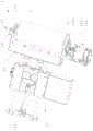
Fig. 1 is a first structural diagram of a first embodiment of the stop adhesive tape dispenser of the present invention.
Fig. 2 is a second structural diagram of the first embodiment of the stop adhesive tape-sticking and adhesive-preparing device of the present invention.
Fig. 3 is a structural diagram of the rubberizing unit of the first embodiment of the stop gum rubberizing and glue preparing device of the present invention.
Fig. 4 is a third structural diagram of the first embodiment of the stop adhesive tape dispenser of the present invention.
Figure 5 is the utility model discloses stop gum rubberizing is equipped with gluey position of being equipped with and rubberizing position schematic diagram of the rubberizing gyro wheel of the first embodiment of rubberizing device.
The present invention will be further explained with reference to the drawings and examples.
Detailed Description
First embodiment of stop gum pasting and glue preparation device:
referring to fig. 1 and 2, the stop adhesive tape applying and preparing device 100 includes a mounting base 1, an adhesive applying unit 2, a tape preparing unit 3, and a cutting unit 4, wherein a first guide rail 11 is disposed on the mounting base 1.
Referring to fig. 3, the taping unit 2 includes a taping roller 21, a first driving mechanism 22, a position finding mechanism 23, and a lock cylinder 24. Wherein, the rubberizing roller 21 has a glue preparing position and a rubberizing position. The rubberizing roller 21 is provided with an air hole group and an air inlet interface, the air hole group is arranged on the peripheral wall of the rubberizing roller 21, and the air hole group is distributed along the axial direction of the rubberizing roller 21. The air inlet interface is communicated with the air hole group through an air flow channel so as to adsorb the adhesive tape 10 or release the adsorption of the adhesive tape 10.
When the adhesive tape sticking roller 21 is in the adhesive preparing position and the adhesive preparing unit 3 transfers the adhesive tape 10 to the adhesive tape sticking roller 21, the air inlet port is ventilated to form negative pressure at the air hole group, so that the adhesive tape 10 transferred by the adhesive preparing unit 3 is adsorbed on the surface of the adhesive tape sticking roller 21; when the rubberizing roller 21 moves to the rubberizing position and the adhesive tape 10 on the rubberizing roller 21 just contacts with the tail end of the battery cell, the air inlet interface stops ventilating, so that the air hole group forms normal pressure, and at the moment, the adhesive tape 10 is attached and smoothed on the battery cell under the actions of the self adhesive force, the rubberizing roller 21 and a winding needle of the battery cell winding machine.
The rubberizing roller 21 is rotatably arranged on the output end of a first driving mechanism 22 around the axis of the rubberizing roller 21, and the first driving mechanism 22 is used for driving the rubberizing roller 21 to move between a rubberizing position and a glue preparing position. Specifically, the first driving mechanism 22 includes a first bracket 221 and a second driving assembly 222, the rubberizing roller 21 is rotatably mounted on the first bracket 221 around its axis, the first bracket 221 is fixedly mounted on the output end of the second driving assembly 222, the first bracket 221 is disposed to better provide a mounting space for the rubberizing roller, and it is ensured that the second driving assembly 222 can stably and reliably drive the rubberizing roller 21 to move between the glue preparation position and the glue application position. In this embodiment, the second driving assembly 222 is a first cylinder, and the first cylinder drives the rubberizing rollers 21 to move along a straight line.
It should be noted that the movement track of the rubberizing roller 21 and the specific structure of the first driving mechanism 22 may be adaptively changed according to the installation space of the end gum rubberizing and glue preparing apparatus 100 and the matching relationship between the end gum rubberizing and glue preparing apparatus 100 and the winding head of the electrical core winding machine, for example, the movement track of the rubberizing roller 21 may be set to be an arc, and the structure of the second driving assembly 222 at this time needs to play a role in driving the rubberizing roller 21 to swing around a fulcrum, and since the structure of the second driving assembly 222 at this time may be designed in a diversified conventional manner, it is not described herein in detail.
Seek position mechanism 23 and be used for seeking the initial point to rubberizing gyro wheel 21 for rubberizing gyro wheel 21 all can reset to the initial position of settlement after accomplishing the rubberizing operation at every turn, guarantee to be equipped with gluey mechanism 32 and can accurately transfer sticky tape 10 to the gas vent group of rubberizing gyro wheel on, so that the gas vent group carries out reliable absorption to sticky tape 10, in addition, when can making rubberizing gyro wheel 21 rubberizing again, its rubberizing position can be accurate, accord with the design requirement, thereby guarantee to stop rubberizing and be equipped with rubberizing quality of mucilage binding device 100.
Specifically, the seek mechanism 23 includes a position sensor 231, a sensing piece 232, and a first drive assembly 233. The position sensor 231 is fixedly installed on the first bracket 221, the sensing piece 232 is fixedly installed at the end of the rotating shaft, and the sensing piece 232 can synchronously rotate along with the rubberizing roller 21. The detection end of the position sensor 231 is disposed toward the sensing piece 232, so that the current position state of the rubberizing roller 21 is identified through the sensing piece 232, and when the rubberizing roller 21 is at the initial position, a detection signal is sent to a control system electrically connected to the end-stop rubberizing and glue-preparing device 100.
The first driving assembly 233 is mounted on the first bracket 221, and the first driving assembly 233 is used for driving the rubberizing roller 21 to rotate, so as to find a point of the rubberizing roller 21. Certainly, when having the design requirement, first drive assembly 233 still can carry out the rubberizing operation in-process at rubberizing gyro wheel 21 and drive rubberizing gyro wheel 21 and rotate for rubberizing gyro wheel 21 can keep the same linear velocity with the book needle of coiling head, thereby makes the laminating that sticky tape 10 can be better on electric core, avoids sticky tape 10 to take place the fold, and guarantees that sticky tape 10 laminating position is accurate. In this embodiment, the first driving assembly 233 includes a first motor 2331 and a driving wheel 2332, wherein the first motor 2331 is mounted on the first bracket 221, and the driving wheel 2332 is fixedly mounted on a motor shaft of the first motor 2331 and is coaxially disposed with the motor shaft of the first motor 2331. The driving wheel 2332 is adjacent to the rubberizing roller 21, and is linked by the friction force between the driving wheel 2332 and the rubberizing roller 21, when the rubberizing roller 21 needs to be driven to rotate, the first motor 2331 drives the driving wheel 2332 to rotate, so that the driving wheel 2332 drives the rubberizing roller 21 to rotate synchronously.
The locking cylinder 24 is installed on the first bracket 221, a rod body of the locking cylinder 24 is disposed toward the rubberizing roller, and the rod body of the locking cylinder 24 is movable to be adjacent to the rubberizing roller 21. Preferably, the rubberizing roller 21 may be provided with a slot hole on an end close to the locking cylinder 24, the slot hole being matched with the locking cylinder 24, so that when the locking cylinder 24 needs to lock the rubberizing roller 21, the rod body of the locking cylinder 24 can extend into the slot hole, thereby locking the rubberizing roller 21 more reliably. The arrangement of the locking cylinder 24 can lock the rubberizing roller 21 when the adhesive tape 10 is transferred to the rubberizing roller 21 by the adhesive preparing mechanism 32, so that the position of the adhesive tape 10 is prevented from being shifted when the adhesive tape is transferred to the rubberizing roller 21, and the accuracy of the rubberizing position of the rubberizing unit 2 is ensured.
Referring to fig. 4, the glue preparing unit 3 includes a glue clamping mechanism 31, a glue preparing mechanism, a second driving mechanism 33, and an unreeling glue-off mechanism 34, the glue clamping mechanism 31 is slidably mounted on the first guide rail 11, and the glue preparing mechanism 32 is disposed at a glue preparing position. The glue clamping mechanism 31 has a glue clamping position, and the second driving mechanism 33 is configured to drive the glue clamping mechanism 31 to slide along the first guide rail 11, so that the glue clamping mechanism 31 moves between the glue clamping position and the glue preparing mechanism 32.
Specifically, the glue clamping mechanism 31 includes two jaw assemblies 311, a third drive assembly 312, and a fourth drive assembly 314. Two clamping jaw assemblies 311 are distributed along the extending direction of the guide rail, and the two clamping jaw assemblies 311 are used for clamping two ends of the adhesive tape 10 at the cutting position. The third driving assembly 312 is used for driving the two jaw assemblies 311 to open or close respectively.
Wherein the third driving assembly 312 comprises two jaw cylinders 3121 and a second support 3122, and one jaw assembly 311 is mounted on the jaw cylinder 3121. The jaw assembly 311 includes two jaws, which are respectively mounted on two jaw ends of the jaw cylinder 3121, so that the jaw cylinder 3121 can drive the two jaws to open or close.
The second support 3122 is provided with a sliding groove 3123, the sliding groove 3123 extends along the extending direction of the first guide rail 11, and the two clamping jaw cylinders 3121 are slidably connected with the sliding groove 3123 along the extending direction of the sliding groove 3123, so that the two clamping jaw cylinders 3121 can move oppositely or away from each other, and the distance between the two clamping jaw cylinders 3121 is adjustable, so as to clamp the adhesive tapes 10 with different lengths.
The second support 3122 is mounted on an output end of the fourth drive assembly 314, the fourth drive assembly 314 is slidably mounted on the first rail 11, and the second drive mechanism 33 drives the fourth drive assembly 314 to slide along the first rail 11. In this embodiment, the fourth driving assembly 314 is a fifth air cylinder, and the fourth driving assembly 314 drives the third driving assembly 312 to move to the glue clamping position or to the glue preparing position along the direction perpendicular to the extending direction of the first guide rail 11. The fourth driving component 314 enables the clamping jaw component 311 to have an avoiding stroke, so that the clamping mechanism 31 is prevented from colliding with the cutting unit 4 in the resetting process, and the structure of the end glue sticking and glue preparing mechanism 32 is optimized.
The second driving mechanism 33 comprises a third motor 331 and a ball screw 332, the third motor 331 is mounted on the mounting base 1, a motor shaft of the third motor 331 is fixedly connected with and coaxially arranged with a screw rod of the ball screw 332, the screw rod is parallel to the first guide rail 11, and the fourth driving component 314 is fixedly connected with a nut of the ball screw 332. The combination of the third motor 331 and the ball screw 332 is adopted as the second driving mechanism 33, so that the moving precision of the adhesive tape clamping mechanism 31 can be ensured, and the length of the adhesive tape 10 at the cutting position can be ensured to meet the processing requirement.
The glue preparing mechanism 32 includes a fourth cylinder 321 and a glue preparing base 322, the glue preparing base 322 is used for receiving the adhesive tape 10 transferred by the glue clamping mechanism 31, and the fourth cylinder 321 is used for driving the glue preparing base 322 to move towards the gluing roller 21, so that the adhesive tape 10 on the glue preparing base 322 can be transferred to the gluing roller 21.
The unwinding and glue-releasing mechanism 34 comprises a third bracket 341, a material reel 342, a slider 343, a fifth driving assembly 344, a glue-releasing wheel set 345 and a guide wheel set 346. The third frame 341 is mounted on the mounting base 1, a second guide rail 3411 is arranged on the third frame 341, and the second guide rail 3411 is arranged perpendicular to the mounting base 1. The material reel 342 is mounted on the third mounting bracket, and the material reel 342 is used for mounting and unwinding the adhesive tape roll.
The slider 343 is slidably mounted on the second guide rail 3411, the fifth driving mechanism is mounted on the third frame 341, and the fifth driving assembly 344 is used for driving the slider 343 to slide along the second guide rail 3411. Preferably, the fifth drive assembly 344 is a sixth air cylinder.
The glue opening wheel group 345 includes a first roller 3451 and two second rollers 3452, wherein the first roller 3451 is rotatably mounted on the sliding block 343 about its own axis, the two second rollers 3452 are rotatably mounted on the third bracket 341 about its own axis, the two second rollers 3452 are located on opposite sides of the second guide rail 3411, and the two second rollers 3452 are both located at the same end of the second guide rail 3411. The adhesive tape opening wheel set 345 is used for being matched with the second guide rail 3411 to unreel the adhesive tape roll better, so that the adhesive tape 10 is pulled open better, the adhesive tape clamping mechanism 31 can drive the adhesive tape 10 to move more smoothly, the adhesive tape 10 is prevented from deforming due to excessive elongation, and the adhesive tape 10 is protected.
The guide wheel set 346 includes a plurality of third rollers, each of which is rotatably installed on the third bracket 341 about its own axis, and the guide wheel set 346 serves to guide the tape 10 being pulled so that the tape 10 can be better brought into the clamping position. Wherein, in the tape running direction of the unwinding glue-opening mechanism 34, the guiding wheel set 346 is disposed between the glue-clamping mechanism 31 and the glue-opening wheel set 345, and the tape 10 with the tape roll pulled off is run as shown in fig. 4. In the process that the adhesive tape 10 is clamped by the clamping mechanism 31 at the clamping position and moves to the adhesive preparation position, the fifth driving assembly 344 can assist in driving the sliding block 343 to move upwards, so as to ensure that the adhesive tape 10 can be smoothly pulled to the adhesive preparation position, and after the adhesive tape 10 at the adhesive preparation position is cut, the fifth driving assembly 344 drives the sliding block 343 to move downwards so as to pull out the adhesive tape 10 on the adhesive tape roll again.
The cutting unit 4 is located between the glue clamping position and the glue preparing position, and the glue clamping position is located between the cutting unit 4 and the unreeling glue-off mechanism 34. The cutting unit 4 includes a pressing mechanism 41 and a cutting mechanism 42, the pressing mechanism 41 has a tape passage, and a cutting blade 421 of the cutting mechanism 42 is disposed toward the tape passage and is movable relative to the tape passage. Specifically, hold-down mechanism 41 includes two second cylinders 411, and the body of rod of two second cylinders 411 sets up in opposite directions, and is provided with briquetting 412 on the body of rod of second cylinder 411, forms the sticky tape passageway between two briquetting 412, cuts the mechanism 42 and includes third cylinder 422 and cutter 421, and the cutting part of cutter 421 sets up towards the sticky tape passageway, and third cylinder 422 drive cutter 421 moves relative sticky tape passageway.
The operation of the stop-off adhesive tape applying and preparing device 100 is described below with reference to fig. 1 to 5:
first, the adhesive tape 10 is wound around the opening roller group 345 and the guide roller group 346 at a time in the winding manner shown in fig. 4, and the means of the adhesive tape 10 is pressed by the pressing mechanism 4141 of the cutting unit 4.
Next, the glue clamping mechanism 31 of the glue preparation unit 3 moves to the glue clamping position, so that the clamping jaw assembly 311 moves to the glue clamping position, specifically, the fourth driving assembly 314 drives the third driving assembly 312 to move forward, so that the clamping jaw assembly 311 moves to the adhesive tape 10, and then the clamping jaw air cylinder 3121 of the third driving assembly 312 drives the clamping jaw assembly 311 to close, so as to clamp the adhesive tape 10.
Then, the two second air cylinders 411 of the pressing mechanism 41 are reset to release the pressing of the adhesive tape 10, and then the second driving mechanism 33 drives the adhesive tape clamping mechanism 31 to move along the guide rail to the adhesive tape preparing mechanism 32 until the adhesive tape clamping mechanism 31 is located at the adhesive tape preparing mechanism 32.
Then, the two second air cylinders 411 of the pressing mechanism 41 are activated again to press the adhesive tape 10 again, and then the third air cylinder 422 of the cutting mechanism 42 drives the cutter 421 to move toward the adhesive tape 10 to cut the adhesive tape 10, and after the cutting of the adhesive tape 10 is completed, the third air cylinder 422 drives the cutter 421 to reset.
Then, the fourth driving component 314 drives the third driving component 312 to move forward again, so that the adhesive tape 10 clamped by the adhesive clamping mechanism 31 is located on the adhesive preparing base 322 of the adhesive preparing mechanism 32, and the adhesive preparing process of the adhesive tape 10 is completed.
Then, the clamping jaw cylinder 3121 of the third driving assembly 312 drives the clamping jaw assembly 311 to open, so as to release the clamping of the adhesive tape 10, and the fourth cylinder 321 of the adhesive preparation mechanism 32 drives the adhesive preparation base 322 to move toward the adhesive applying roller 21. At this time, the air inlet of the rubberizing roller 21 is ventilated, so that a negative pressure is formed on the air hole group of the rubberizing roller 21 to suck the adhesive tape 10 from the adhesive preparing base 322 to the rubberizing roller 21.
Then, the third driving assembly 312 and the fourth driving assembly 314 are reset, the second driving mechanism 33 drives the glue clamping mechanism 31 to reset, and as shown in fig. 5, the first driving mechanism 22 of the gluing unit 2 drives the gluing roller 21 to move from the glue preparing position a to the gluing position B, so as to glue the battery cell wound by the winding head. At this time, the glue preparation unit 3 can repeat the glue preparation process.
After the rubberizing roller 21 finishes rubberizing processing, the first driving mechanism 22 drives the rubberizing roller 21 to reset to the standby position a from the rubberizing position B, the first driving component 233 of the locating mechanism 23 drives the rubberizing roller 21 to rotate, the position sensor 231 detects the position of the rubberizing roller 21 through the sensing sheet 232, when the rubberizing roller 21 rotates to the set initial position, the position sensor 231 sends a detection signal to a control system of the electric core winder, so that the control system controls the first driving component 233 to stop driving the rubberizing roller 21, at this time, the origin searching operation of the rubberizing roller 21 is finished, the air hole group of the rubberizing roller 21 faces the standby seat 322, and the next transfer of the adhesive tape 10 of the standby seat 322 is waited.
Second embodiment of the stop adhesive tape sticking and adhesive preparing apparatus:
the difference between this embodiment and the first embodiment of the stop glue application and preparation device is that:
the first driving assembly comprises a second motor and a one-way clutch, the second motor is installed on the first support, a motor shaft of the second motor is coaxially arranged with the rubberizing roller, and the one-way clutch is connected between the motor shaft and the end portion of the rubberizing roller. Through the setting, the driving rubberizing roller capable of being reliable can be driven by the second motor to rotate, so that the problem that the driving wheel cannot reliably drive the rubberizing roller to keep synchronous rotation due to undersize friction force between the driving wheel and the rubberizing roller, which possibly exists in the first embodiment of the stop rubberizing glue preparation device, is avoided. And one-way clutch then can avoid when rubberizing gyro wheel and electric core contact, the inherent resistance of the motor shaft of second motor hinders the rubberizing gyro wheel and follows the condition emergence that the book needle carries out synchronous rotation.
Stop gum rubberizing is equipped with mucilage binding and is put:
the difference between this embodiment and the second embodiment of the stop glue application and preparation device is that:
will connect the one-way clutch between second motor and rubberizing gyro wheel and change for the shaft coupling, and should set up and to satisfy the rubberizing gyro wheel and need have initiative pivoted designing requirement when carrying out the rubberizing operation, when the rubberizing gyro wheel is carrying out the rubberizing operation promptly, the second motor can rotate through the reliable drive rubberizing gyro wheel of shaft coupling, make the rubberizing gyro wheel can keep the same linear velocity with the book needle of coiling head, thereby make laminating that the sticky tape can be better on electric core, avoid the sticky tape to take place the fold, and guarantee that sticky tape laminating position is accurate.
Square power electrical core winder embodiment:
the square power electric core winder comprises the stop adhesive tape sticking and preparing device in any one of the first embodiment to the third embodiment of the stop adhesive tape sticking and preparing device, and the square power electric core winder provided with the stop adhesive tape sticking and preparing device can effectively shorten the period of electric core tape sticking, improve the production efficiency and realize high-speed production.
Finally, it should be emphasized that the above-described embodiments are merely preferred examples of the present invention, and are not intended to limit the invention, as those skilled in the art will appreciate that various changes and modifications may be made, and any and all modifications, equivalents, and improvements made, while remaining within the spirit and principles of the present invention, are intended to be included within the scope of the present invention.
Claims (10)
1. Stop rubberizing and be equipped with mucilage binding and put, its characterized in that includes:
the mounting base is provided with a first guide rail;
the adhesive tape sticking unit comprises an adhesive tape sticking roller and a first driving mechanism, wherein an air hole group is arranged on the adhesive tape sticking roller, the adhesive tape sticking roller is rotatably arranged on the output end of the first driving mechanism around the axis of the adhesive tape sticking roller, the adhesive tape sticking roller is provided with an adhesive tape sticking position and an adhesive tape preparing position, and the first driving mechanism drives the adhesive tape sticking roller to move between the adhesive tape sticking position and the adhesive tape preparing position;
the glue preparing unit comprises a glue clamping mechanism, a glue preparing mechanism and a second driving mechanism, the glue clamping mechanism is slidably mounted on the first guide rail, the glue preparing mechanism is arranged at the glue preparing position, the glue clamping mechanism is provided with a glue clamping position, and the second driving mechanism drives the glue clamping mechanism to move between the glue clamping position and the glue preparing mechanism along the first guide rail;
the cutting unit is located between the glue clamping position and the glue preparing position, the cutting unit comprises a pressing mechanism and a cutting mechanism, the pressing mechanism is provided with a tape channel, and a cutter of the cutting mechanism is arranged towards the tape channel and can move relative to the tape channel.
2. The stop adhesive tape-applying and glue-preparing device according to claim 1, characterized in that:
the rubberizing unit is still including seeking a mechanism, it includes position sensor, response piece and first drive assembly to seek a mechanism, position sensor with first drive assembly all installs on first drive assembly's output, the response piece is installed on the rubberizing gyro wheel, position sensor's sense terminal orientation the setting of response piece, first drive assembly can drive the rubberizing gyro wheel rotates.
3. The stop adhesive tape-applying and glue-preparing device according to claim 2, characterized in that:
the rubberizing unit further comprises a locking cylinder, the locking cylinder is installed on the output end of the first driving mechanism, and a rod body of the locking cylinder can move to be adjacent to the rubberizing roller.
4. The stop adhesive tape-applying and glue-preparing device according to claim 2, characterized in that:
the first driving assembly comprises a first motor and a driving wheel, the first motor is arranged at the output end of the first driving mechanism, the driving wheel is arranged on a motor shaft of the first motor, and the driving wheel is adjacent to the rubberizing roller; or
The first driving assembly comprises a second motor and a one-way clutch, the second motor is installed at the output end of the first driving mechanism, a motor shaft of the second motor is coaxially arranged with the rubberizing roller, and the one-way clutch is connected between the motor shaft and the rubberizing roller.
5. The stop-adhesive tape-applying and glue-preparing device according to any one of claims 2 to 4, characterized in that:
the first driving mechanism comprises a first bracket and a second driving assembly, the first bracket is arranged at the output end of the second driving assembly, and the rubberizing roller, the position sensor and the first driving assembly are all arranged on the first bracket;
the second driving assembly is a first air cylinder, and the first air cylinder drives the rubberizing roller to move along a straight line.
6. The stop adhesive tape-applying and glue-preparing device according to claim 1, characterized in that:
doubling mechanism includes:
two jaw assemblies distributed along the first guide rail;
the third driving assembly drives the two clamping jaw assemblies to open or close respectively;
the fourth driving assembly is slidably mounted on the first guide rail, the second driving mechanism drives the fourth driving assembly to slide along the first guide rail, and the fourth driving assembly can drive the third driving assembly to move to the glue clamping position or the glue preparing position.
7. The stop adhesive tape-applying and glue-preparing device according to claim 6, characterized in that:
the third drive assembly includes:
the clamping jaw air cylinder drives the two clamping jaws of the clamping jaw assembly to move towards or away from each other;
the second support is provided with a sliding groove, the sliding groove extends along the extending direction of the first guide rail, and the two clamping jaw cylinders are connected with the sliding groove in a sliding mode along the extending direction of the sliding groove respectively.
8. The stop adhesive tape-applying and glue-preparing device according to claim 1, characterized in that:
the pressing mechanism comprises two second air cylinders, the rod bodies of the two second air cylinders are arranged oppositely, pressing blocks are arranged on the rod bodies of the second air cylinders, and the adhesive tape channel is formed between the two pressing blocks;
the cutting mechanism comprises a third cylinder and the cutter, the cutting edge of the cutter is arranged towards the adhesive tape channel, and the third cylinder drives the cutter to move relative to the adhesive tape channel;
the glue preparing mechanism comprises a fourth cylinder and a glue preparing base, and the fourth cylinder can drive the glue preparing base to move towards the gluing roller.
9. The stop-off adhesive tape applicator according to any one of claims 1 to 4 and 6 to 8, wherein:
it still includes unreels the rubber cutting machine to be equipped with gluey unit, it includes to unreel the rubber cutting machine:
the third support is arranged on the mounting seat, and a second guide rail is arranged on the third support;
a material reel rotatably mounted on the third support about its own axis;
a slider slidably mounted on the second rail;
the fifth driving assembly drives the sliding block to slide along the second guide rail;
the rubber stripping wheel set comprises a first roller and two second rollers, the first roller is installed on the sliding block, the two second rollers are respectively located on two opposite sides of the second guide rail, and the two second rollers are located at the same end part of the second guide rail;
the guide wheel set is arranged between the laminating mechanism and the glue opening wheel set.
10. A square power electric core winder comprising the stop gum pasting and glue preparing device of any one of claims 1 to 9.
Priority Applications (1)
| Application Number | Priority Date | Filing Date | Title |
|---|---|---|---|
| CN201922489943.6U CN211017275U (en) | 2019-12-30 | 2019-12-30 | Stop rubber rubberizing is equipped with mucilage binding and is put and square power electricity core winder |
Applications Claiming Priority (1)
| Application Number | Priority Date | Filing Date | Title |
|---|---|---|---|
| CN201922489943.6U CN211017275U (en) | 2019-12-30 | 2019-12-30 | Stop rubber rubberizing is equipped with mucilage binding and is put and square power electricity core winder |
Publications (1)
| Publication Number | Publication Date |
|---|---|
| CN211017275U true CN211017275U (en) | 2020-07-14 |
Family
ID=71477466
Family Applications (1)
| Application Number | Title | Priority Date | Filing Date |
|---|---|---|---|
| CN201922489943.6U Active CN211017275U (en) | 2019-12-30 | 2019-12-30 | Stop rubber rubberizing is equipped with mucilage binding and is put and square power electricity core winder |
Country Status (1)
| Country | Link |
|---|---|
| CN (1) | CN211017275U (en) |
-
2019
- 2019-12-30 CN CN201922489943.6U patent/CN211017275U/en active Active
Similar Documents
| Publication | Publication Date | Title |
|---|---|---|
| CN114300757A (en) | Automatic reel changing and belt splicing mechanism | |
| CN206401446U (en) | A kind of automatic sticking patch device | |
| CN108701869B (en) | Automatic tape changing device for winding battery cell and battery cell winding equipment | |
| CN211125870U (en) | Rubberizing device | |
| CN108675039B (en) | Winding process for realizing zero-speed punching and automatic rubberizing of lithium battery pole piece | |
| CN202167581U (en) | Adhesive tape adhering mechanism of battery winder | |
| CN108657864B (en) | Automatic paste double faced adhesive tape device | |
| CN110994043A (en) | Double-station rotary rubberizing device and electric core winding machine | |
| CN103311497B (en) | Pole piece rubberizing device | |
| CN211507800U (en) | Rubberizing device and electricity core winder | |
| CN211017275U (en) | Stop rubber rubberizing is equipped with mucilage binding and is put and square power electricity core winder | |
| CN210167470U (en) | Automatic continuous tape splicing and unwinding mechanism | |
| CN216720028U (en) | Lithium battery rubberizing unloading mechanism and lithium battery winding device | |
| CN209097851U (en) | Automatic upper core wound packages is set and containing its bundling equipment | |
| CN111048823A (en) | Pole piece cutting and rubberizing device and processing method thereof and square power electric core winding machine | |
| CN207497786U (en) | It is a kind of to automate device of taping | |
| CN218827308U (en) | Rubberizing subassembly, ending and gluing mechanism and take-up device | |
| CN114551650B (en) | Packaging equipment for solar photovoltaic panel production | |
| CN211879512U (en) | Rubberizing device | |
| CN214411270U (en) | Adhesive tape forming device | |
| CN211110261U (en) | Rubberizing subassembly and rubberizing mechanism | |
| CN212402861U (en) | Pole piece feeding unit, winding device and electric core winding machine | |
| CN113246642A (en) | File bag sealing device | |
| CN208814330U (en) | The winding automatic rubberizing Feng Juan mechanism end to end of self-adhesive paper cutting or rewinding machine | |
| CN211507801U (en) | Paste termination and glue unit, take-up device and electricity core winder |
Legal Events
| Date | Code | Title | Description |
|---|---|---|---|
| GR01 | Patent grant | ||
| GR01 | Patent grant |