CN210999384U - Low dust type concrete mixer - Google Patents
Low dust type concrete mixer Download PDFInfo
- Publication number
- CN210999384U CN210999384U CN201920971174.0U CN201920971174U CN210999384U CN 210999384 U CN210999384 U CN 210999384U CN 201920971174 U CN201920971174 U CN 201920971174U CN 210999384 U CN210999384 U CN 210999384U
- Authority
- CN
- China
- Prior art keywords
- dust
- motor
- rotating shaft
- main body
- dust suction
- Prior art date
- Legal status (The legal status is an assumption and is not a legal conclusion. Google has not performed a legal analysis and makes no representation as to the accuracy of the status listed.)
- Active
Links
Images


Abstract
The utility model discloses a low-dust concrete mixer, which comprises a mixing main body, a motor frame, a second rotating shaft, a feed inlet, a dust collecting box, a spiral mixing blade and a controller, wherein four supporting legs are uniformly arranged below the mixing main body, and the motor frame is arranged in the middle of the upper part of the mixing main body; a first motor is arranged above the motor frame, and a second rotating shaft is inserted below the second motor; a spiral stirring blade is arranged below the second rotating shaft, and a cleaning rod is arranged on one side of the supporting rod on the left side, which is far away from the second rotating shaft; and a third rotating shaft and a fourth rotating shaft are respectively arranged on the left side and the right side in the middle of the feed inlet, a first crushing roller is arranged on the third rotating shaft, and a second crushing roller is arranged on the fourth rotating shaft. The utility model discloses a cooperation between dust catcher, dust absorption hole, suction hood and the dust collection box that set up is used, can absorb the dust that produces when reinforced to the charge door, realizes the low dust stirring, environmental protection more.
Description
Technical Field
The utility model relates to a concrete mixer field specifically is low dust formula concrete mixer.
Background
The concrete is mainly made of cement, water, sand and stones, chemical additives and mineral admixtures are added as necessary, the cement, the sand, the stones and the artificial stone are matched according to a proper proportion and are uniformly stirred, densely formed and cured to form the artificial stone, the concrete is traditionally stirred manually, time and labor are consumed, the working efficiency is low, along with the development of science and technology and the progress of times, the stirring of the concrete is basically completed through a concrete mixer at present, but most of existing concrete mixers are used, a large amount of dust is easily generated, the dust is diffused in the air to easily pollute the environment, the environment is not friendly, and meanwhile, the dust generates great harm to the bodies of workers.
SUMMERY OF THE UTILITY MODEL
An object of the utility model is to provide a low dust formula concrete mixer to solve the problem that proposes among the above-mentioned background art.
In order to achieve the above object, the utility model provides a following technical scheme:
the low-dust type concrete mixer comprises a mixing main body, a motor frame, a second rotating shaft, a feeding hole, a dust collection box, a spiral mixing blade and a controller, wherein four supporting legs are uniformly arranged below the mixing main body, pulleys are arranged below the supporting legs, and the motor frame is arranged in the middle of the upper part of the mixing main body; a first motor is arranged above the motor frame, a first rotating shaft is arranged on the right side of the first motor, a rotating disc is arranged on the right side of the first rotating shaft, a first connecting rod is arranged on the right side of the rotating disc, a connecting piece is arranged below the right side of the first connecting rod, a limiting block is arranged on the right side of the connecting piece, a second connecting rod is arranged below the connecting piece, a connecting seat is arranged below the second connecting rod, the lower part of the connecting seat is connected to the second motor, a second rotating shaft is inserted below the second motor, and a guide hole is formed between the second rotating shaft and the stirring main body; a spiral stirring blade is arranged below the second rotating shaft, supporting rods are arranged on the left side and the right side of the middle of the second rotating shaft, a cleaning rod is arranged on one side, away from the second rotating shaft, of the supporting rod on the left side, and a plurality of cleaning brushes are uniformly distributed on one side, close to the inner wall of the stirring main body, of the cleaning rod; a feed inlet is arranged above the left side of the stirring main body, a plurality of dust collection holes are uniformly distributed on the left side and the right side of the feed inlet, dust collection covers are arranged on shells of the dust collection holes on the left side and the right side respectively, a first dust collection pipe is arranged on one side, away from the dust collection holes, of each dust collection cover, the first dust collection pipes on the left side and the right side are connected to a second dust collection pipe, a dust collector is arranged on the second dust collection pipe, the right side of the second dust collection pipe is connected into a dust collection box, the dust collection box is arranged on the right side above the stirring main body, a filter screen is arranged above the inner part; third pivot and fourth pivot are installed respectively to the left and right sides in the middle of the feed inlet, install first crushing roller in the third pivot, install the second crushing roller in the fourth pivot, the third motor is installed to the rear side of third pivot, the fourth motor is installed to the rear side of fourth pivot, the rotation opposite direction of third motor and fourth motor, install the controller in the middle of the right side of stirring main part, the inlet tube is installed to the top on stirring main part right side, the inside top of stirring main part is installed to the inlet tube, the below equipartition that is located the inlet tube of the inside top of stirring main part is provided with a plurality of nozzles.
As a further aspect of the present invention: the middle of the supporting rod is inserted with a sliding rod, the sliding rod is sleeved with a first spring, and one side, far away from the second rotating shaft, of the supporting rod on the right side is provided with a wall scraping rod.
As a further aspect of the present invention: ejector rods are arranged on the left side and the right side above the filter screen, pull rods are arranged above the ejector rods, and second springs are connected between the lower portions of the left side and the right side of each pull rod and the dust collection box.
As a further proposal of the utility model, the controller is a P L C controller, and the controller is electrically connected with the first motor, the second motor, the third motor, the fourth motor and the dust collector through leads.
As a further aspect of the present invention: the middle of the lower part of the stirring main body is provided with a discharge hole, and a control valve is arranged on the discharge hole.
Compared with the prior art, the utility model can absorb the dust generated when the charging hole is charged through the matching use of the dust collector, the dust absorption hole, the dust absorption cover and the dust collection box, thereby realizing low-dust stirring and being more environment-friendly; through the matched use of the first motor, the first rotating shaft, the rotating disc, the first connecting rod, the connecting piece and the second connecting rod, the spiral stirring blade can move up and down in a reciprocating manner, so that the stirring range of the spiral stirring blade in the stirring main body is wider, and the stirring is more efficient; the filter screen can vibrate up and down through the matching use of the arranged pull rod, the ejector rod and the second spring, so that dust is prevented from being attached to the lower surface of the filter screen to block the filter tip; the wall scraping rod and the cleaning brush are matched for use, so that concrete materials can be prevented from being adhered to the inner wall of the stirring main body.
Drawings
FIG. 1 is a schematic view showing the construction of a low-dust concrete mixer.
FIG. 2 is a schematic side view of a first connecting rod and a second connecting rod of the low dust concrete mixer.
FIG. 3 is a schematic view of a support rod of the low dust concrete mixer.
FIG. 4 is an enlarged schematic view of A in the low dust type concrete mixer.
FIG. 5 is a schematic top view of the first crushing roller and the second crushing roller of the low dust type concrete mixer.
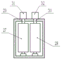
In the figure: 1. a stirring body; 2. supporting legs; 3. a pulley; 4. a motor frame; 5. a first motor; 6. a first rotating shaft; 7. A turntable; 8. a first connecting rod; 9. a connecting member; 10. a limiting block; 11. a second connecting rod; 12. a connecting seat; 13. a second motor; 14. a second rotating shaft; 15. a feed inlet; 16. a dust collection hole; 17. a dust hood; 18. a first dust suction pipe; 19. a second dust suction pipe; 20. a vacuum cleaner; 21. a dust collection box; 22. a filter screen; 23. an exhaust port; 24. a top rod; 25. a pull rod; 26. A second spring; 27. a first crushing roller; 28. a second crushing roller; 29. a third rotating shaft; 30. a fourth rotating shaft; 31. a third motor; 32. a fourth motor; 33. a spiral stirring blade; 34. a support bar; 35. a slide bar; 36. a controller; 37. cleaning the rod; 38. cleaning a brush; 39. a discharge port; 40. a control valve; 41. a guide hole; 42. a wall scraping rod; 43. a water inlet pipe; 44. And (4) a nozzle.
Detailed Description
The technical solution of the present patent will be described in further detail with reference to the following embodiments.
Referring to fig. 1-5, the low dust type concrete mixer includes a mixer body 1, a motor frame 4, a second rotating shaft 14, a feeding port 15, a dust collecting box 21, a spiral mixing blade 33 and a controller 36; four supporting legs 2 are installed to the below equipartition of stirring main part 1, and pulley 3 is installed to the below of supporting legs 2, installs motor frame 4 in the middle of the top of stirring main part 1.
As shown in fig. 2, a first motor 5 is installed above the motor frame 4, the model of the first motor 5 is Y160M-6, 7.5KW,1500r/min, a first rotating shaft 6 is installed on the right side of the first motor 5, a rotating disc 7 is installed on the right side of the first rotating shaft 6, a first connecting rod 8 is installed on the right side of the rotating disc 7, a connecting member 9 is installed below the right side of the first connecting rod 8, a limiting block 10 is arranged on the right side of the connecting member 9, a second connecting rod 11 is installed below the connecting member 9, a connecting seat 12 is installed below the second connecting rod 11, the lower part of the connecting seat 12 is connected to a second motor 13, the model of the second motor 13 is Y160M1-2, 11KW, 3000r/min, a second rotating shaft 14 is inserted below the second motor 13, and a guide hole 41 is arranged between the second rotating shaft 14 and the stirring main body 1.
As shown in fig. 1 and 3, a spiral stirring blade 33 is installed below the second rotating shaft 14, and by providing the spiral stirring blade 33, while concrete is stirred, the concrete materials are lifted upwards, so that the stirring is more sufficient, the concrete materials are prevented from being accumulated at the bottom of the stirring main body 1, the support rods 34 are arranged at the left side and the right side in the middle of the second rotating shaft 14, the slide rod 35 is inserted in the middle of the support rod 34, the slide rod 35 is sleeved with the first spring, the wall scraping rod 42 is arranged at one side of the support rod 34 at the right side, which is far away from the second rotating shaft 14, the cleaning rod 37 is arranged at one side of the support rod 34 at the left side, which is far away from the second rotating shaft 14, the cleaning brushes 38 are uniformly distributed at one side of the cleaning rod 37, the inner wall of the stirring main body 1 can be kept clean by the matched use of the wall scraping rod 42 and the cleaning brush 38, and concrete materials are prevented from being adhered to the inner wall of the stirring main body 1.
As shown in fig. 1 and 4, a feed inlet 15 is installed above the left side of the stirring main body 1, a plurality of dust suction holes 16 are uniformly distributed on the left and right sides of the feed inlet 15, dust suction covers 17 are installed on the shells of the dust suction holes 16 on the left and right sides, first dust suction pipes 18 are installed on the sides of the dust suction covers 17 far away from the dust suction holes 16, the first dust suction pipes 18 on the left and right sides are connected to second dust suction pipes 19, dust collectors 20 are installed on the second dust suction pipes 19, the right sides of the second dust suction pipes 19 are connected to a dust collection box 21, the dust collection box 21 is installed on the right side above the stirring main body 1, a filter screen 22 is installed above the dust collection box 21, an exhaust outlet 23 is installed in the middle above the dust collection box 21, raised dust can be absorbed when concrete materials are added into the stirring main body 1 by the cooperation of the dust suction holes 16, the dust suction covers 17 and the dust collectors 20, and gas can be exhausted after the dust, ejector rods 24 are installed on the left side and the right side above the filter screen 22, pull rods 25 are installed above the ejector rods 24, second springs 26 are connected between the lower portions of the left side and the right side of each pull rod 25 and the dust collection box 21, the pull rods 25 are pulled upwards to drive the ejector rods 24 to move upwards, the pull rods 25 are loosened, the ejector rods 24 rapidly move downwards under the action of the second springs 26, the filter screen 22 is hit to vibrate up and down on the filter screen 22, and dust can be prevented from being attached to the lower surface of the filter screen 22 to block the filter screen 22.
As shown in fig. 1 and 5, a third rotating shaft 29 and a fourth rotating shaft 30 are respectively installed on the left and right sides of the middle of the feeding hole 15, a first crushing roller 27 is installed on the third rotating shaft 29, a second crushing roller 28 is installed on the fourth rotating shaft 30, a third motor 31 is installed on the rear side of the third rotating shaft 29, a fourth motor 32 is installed on the rear side of the fourth rotating shaft 30, the third motor 31 and the fourth motor 32 are both ac motors with a rated power of 55-355KW, specifically, the model is YRKK3551-4 ac motor, the rotating directions of the third motor 31 and the fourth motor 32 are opposite, a controller 36 is installed on the middle of the right side of the stirring main body 1, the controller 36 is a P L C controller, the controller 36 is electrically connected with the first motor 5, the second motor 13, the third motor 31, the fourth motor 32 and the dust collector 20 through wires, a discharging hole 39 is formed in the middle of the lower portion of the stirring main body 1, a control valve 40 is arranged on the discharging hole 39, a water inlet pipe 43 is installed on the upper portion of the right side of the stirring main body 1, and a plurality of water inlet pipes 44 are uniformly distributed below the stirring.
In the use process of the utility model, firstly, the concrete material is added into the stirring main body 1 through the feed inlet 15, and water is added into the stirring main body 1 through the water inlet pipe 43, the third motor 31 and the fourth motor 32 respectively drive the third rotating shaft 29 and the fourth rotating shaft 30 to rotate, the third rotating shaft 29 and the fourth rotating shaft 30 respectively drive the first crushing roller 27 and the second crushing roller 28 to rotate, the concrete material is crushed, meanwhile, the dust collector 20 starts to work, the dust generated in the feed inlet 15 is absorbed, the dust is collected into the dust collection box 21, and the absorbed gas is filtered by the filter screen 22 and then is discharged; drive second pivot 14 through second motor 13 and rotate, second pivot 14 drives bracing piece 34 and spiral stirring leaf 33 respectively and rotates, the concrete material of spiral stirring leaf 33 in to stirring main part 1 stirs, first motor 5 drives first pivot 6 and rotates simultaneously, first pivot 6 drives carousel 7 and rotates, carousel 7 drives head rod 8 and rotates, through head rod 8, connecting piece 9, second connecting rod 11, the cooperation transmission between connecting seat 12, make second motor 13 reciprocating motion from top to bottom, second motor 13 drives second pivot 14 up-and-down reciprocating motion, second pivot 14 drives spiral stirring leaf 33 reciprocating motion from top to bottom, make the stirring scope of spiral stirring leaf 33 wider.
In the description of the present invention, it is to be noted that, unless otherwise explicitly specified or limited, the terms "mounted," "connected," and "connected" are to be construed broadly, and may be, for example, fixedly connected, detachably connected, or integrally connected; can be mechanically or electrically connected; they may be connected directly or indirectly through intervening media, or they may be interconnected between two elements. The specific meaning of the above terms in the present invention can be understood by those of ordinary skill in the art through specific situations.
Although the preferred embodiments of the present patent have been described in detail, the present patent is not limited to the above embodiments, and various changes can be made without departing from the spirit of the present patent within the knowledge of those skilled in the art.
Claims (5)
1. The low-dust type concrete mixer comprises a mixing main body (1), a motor frame (4), a second rotating shaft (14), a feeding hole (15), a dust collection box (21), a spiral mixing blade (33) and a controller (36), and is characterized in that four supporting legs (2) are uniformly distributed below the mixing main body (1), pulleys (3) are arranged below the supporting legs (2), and the motor frame (4) is arranged in the middle of the upper part of the mixing main body (1); a first motor (5) is installed above the motor frame (4), a first rotating shaft (6) is installed on the right side of the first motor (5), a rotating disc (7) is installed on the right side of the first rotating shaft (6), a first connecting rod (8) is installed on the right side of the rotating disc (7), a connecting piece (9) is installed below the right side of the first connecting rod (8), a limiting block (10) is arranged on the right side of the connecting piece (9), a second connecting rod (11) is installed below the connecting piece (9), a connecting seat (12) is installed below the second connecting rod (11), the lower portion of the connecting seat (12) is connected to a second motor (13), a second rotating shaft (14) is inserted below the second motor (13), and a guide hole (41) is formed between the second rotating shaft (14) and the stirring main body (1); a spiral stirring blade (33) is arranged below the second rotating shaft (14), supporting rods (34) are arranged on the left side and the right side of the middle of the second rotating shaft (14), a cleaning rod (37) is arranged on one side, far away from the second rotating shaft (14), of the supporting rod (34) on the left side, and a plurality of cleaning brushes (38) are uniformly distributed on one side, close to the inner wall of the stirring main body (1), of the cleaning rod (37); a feed inlet (15) is arranged above the left side of the stirring main body (1), a plurality of dust suction holes (16) are uniformly distributed on the left side and the right side of the feed inlet (15), dust suction covers (17) are arranged on shells of the dust suction holes (16) on the left side and the right side, first dust suction pipes (18) are arranged on one sides, far away from the dust suction holes (16), of the dust suction covers (17), the first dust suction pipes (18) on the left side and the right side are connected to second dust suction pipes (19), dust collectors (20) are arranged on the second dust suction pipes (19), the right sides of the second dust suction pipes (19) are connected into dust collection boxes (21), the dust collection boxes (21) are arranged on the right side above the stirring main body (1), filter screens (22) are arranged above the dust collection boxes (21), and exhaust ports (23) are arranged in the middle of; third pivot (29) and fourth pivot (30) are installed respectively to the left and right sides in the middle of feed inlet (15), install first crushing roller (27) on third pivot (29), install second crushing roller (28) on fourth pivot (30), third motor (31) are installed to the rear side of third pivot (29), fourth motor (32) are installed to the rear side of fourth pivot (30), the rotation direction of third motor (31) and fourth motor (32) is opposite, install controller (36) in the middle of the right side of stirring main part (1), inlet tube (43) are installed to the top on stirring main part (1) right side, the inside top in stirring main part (1) is installed to inlet tube (43), the below equipartition that is located inlet tube (43) of stirring main part (1) inside top is provided with a plurality of nozzles (44).
2. A low dust concrete mixer according to claim 1, wherein a slide bar (35) is inserted into the middle of the support bar (34), a first spring is sleeved on the slide bar (35), and a wall scraping bar (42) is installed on the side of the support bar (34) on the right side away from the second rotating shaft (14).
3. A low dust type concrete mixer according to claim 1, wherein push rods (24) are installed on the left and right sides above said filter net (22), pull rods (25) are installed above said push rods (24), and second springs (26) are connected between the lower parts of the left and right sides of said pull rods (25) and said dust box (21).
4. A low-dust type concrete mixer according to claim 1, wherein the controller (36) is a P L C controller, and the controller (36) is electrically connected with the first motor (5), the second motor (13), the third motor (31), the fourth motor (32) and the dust collector (20) through wires.
5. A low dust concrete mixer according to claim 1, wherein a discharge outlet (39) is provided in the middle of the lower part of the mixer body (1), and a control valve (40) is provided on the discharge outlet (39).
Priority Applications (1)
| Application Number | Priority Date | Filing Date | Title |
|---|---|---|---|
| CN201920971174.0U CN210999384U (en) | 2019-06-26 | 2019-06-26 | Low dust type concrete mixer |
Applications Claiming Priority (1)
| Application Number | Priority Date | Filing Date | Title |
|---|---|---|---|
| CN201920971174.0U CN210999384U (en) | 2019-06-26 | 2019-06-26 | Low dust type concrete mixer |
Publications (1)
| Publication Number | Publication Date |
|---|---|
| CN210999384U true CN210999384U (en) | 2020-07-14 |
Family
ID=71473602
Family Applications (1)
| Application Number | Title | Priority Date | Filing Date |
|---|---|---|---|
| CN201920971174.0U Active CN210999384U (en) | 2019-06-26 | 2019-06-26 | Low dust type concrete mixer |
Country Status (1)
| Country | Link |
|---|---|
| CN (1) | CN210999384U (en) |
Cited By (6)
| Publication number | Priority date | Publication date | Assignee | Title |
|---|---|---|---|---|
| CN112171901A (en) * | 2020-09-10 | 2021-01-05 | 深圳丰发一诺科技有限公司 | Effectual concrete mixing device |
| CN112871779A (en) * | 2021-01-18 | 2021-06-01 | 马龙祥 | Automobile parts rust cleaning equipment |
| CN112934411A (en) * | 2021-02-25 | 2021-06-11 | 南京斯弗日用品有限公司 | Concrete crushing and screening equipment for hydraulic engineering |
| CN113006801A (en) * | 2021-03-17 | 2021-06-22 | 云南泺决建材有限公司 | Device and method for processing micro-expansion grouting material special for tunnel |
| CN113578507A (en) * | 2021-08-12 | 2021-11-02 | 四川科力特机械设备有限公司 | High-efficient dust protected rubbing crusher system |
| CN117225536A (en) * | 2023-11-10 | 2023-12-15 | 连云港活力预拌砂浆有限公司 | Crushing auxiliary equipment for premixed mortar production |
-
2019
- 2019-06-26 CN CN201920971174.0U patent/CN210999384U/en active Active
Cited By (8)
| Publication number | Priority date | Publication date | Assignee | Title |
|---|---|---|---|---|
| CN112171901A (en) * | 2020-09-10 | 2021-01-05 | 深圳丰发一诺科技有限公司 | Effectual concrete mixing device |
| CN112871779A (en) * | 2021-01-18 | 2021-06-01 | 马龙祥 | Automobile parts rust cleaning equipment |
| CN112934411A (en) * | 2021-02-25 | 2021-06-11 | 南京斯弗日用品有限公司 | Concrete crushing and screening equipment for hydraulic engineering |
| CN113006801A (en) * | 2021-03-17 | 2021-06-22 | 云南泺决建材有限公司 | Device and method for processing micro-expansion grouting material special for tunnel |
| CN113578507A (en) * | 2021-08-12 | 2021-11-02 | 四川科力特机械设备有限公司 | High-efficient dust protected rubbing crusher system |
| CN113578507B (en) * | 2021-08-12 | 2023-08-11 | 四川科力特机械设备有限公司 | Efficient dust-proof pulverizer system |
| CN117225536A (en) * | 2023-11-10 | 2023-12-15 | 连云港活力预拌砂浆有限公司 | Crushing auxiliary equipment for premixed mortar production |
| CN117225536B (en) * | 2023-11-10 | 2024-03-22 | 连云港活力预拌砂浆有限公司 | Crushing auxiliary equipment for premixed mortar production |
Similar Documents
| Publication | Publication Date | Title |
|---|---|---|
| CN210999384U (en) | Low dust type concrete mixer | |
| CN216578513U (en) | Adsorption equipment is used in mortar production | |
| CN206121597U (en) | Brick and tile production is with mixed mixer of raw materials | |
| CN211137576U (en) | High-efficient spraying device for porous ceramic processing | |
| CN210522080U (en) | Dust absorbing device is used in cable material processing production | |
| CN112275625A (en) | Sand screening system for engineering supervision construction and screening method thereof | |
| CN205587090U (en) | Environmental protection dust removal rotary drum stone crusher | |
| CN212919929U (en) | Concrete mixing plant blendor dust keeper | |
| CN215241793U (en) | Recycled concrete apparatus for producing | |
| CN215549707U (en) | Mixer for construction | |
| CN215611940U (en) | Waste residue processing apparatus is used in cold rolling processing of linseed that filter effect is good | |
| CN213500041U (en) | Recycled concrete stirring dust collector | |
| CN214914346U (en) | Preparation regeneration mixes earth feed bin with environmental protection dust collector | |
| CN211193115U (en) | Numerical control machine tool capable of recycling metal scraps | |
| CN211329095U (en) | Production of fibre expanding agent is with compounding equipment that contains vertical self-cleaning structure | |
| CN111012241A (en) | Hand-held type dust catcher | |
| CN220047960U (en) | Asphalt stirrer capable of efficiently stirring | |
| CN214078011U (en) | Self-suction type side outlet underwater fishing net cleaning device | |
| CN216799249U (en) | Green environment-friendly dust removal device for concrete mixing plant | |
| CN114160509B (en) | Building engineering building stones belt cleaning device | |
| CN213791101U (en) | Putty powder mixer | |
| CN216150356U (en) | Grit sieving mechanism for construction | |
| CN213611004U (en) | Production device of water-based insulating paint | |
| CN214026342U (en) | A device for concrete mixing | |
| CN218373285U (en) | Highway marking device |
Legal Events
| Date | Code | Title | Description |
|---|---|---|---|
| GR01 | Patent grant | ||
| GR01 | Patent grant |