CN210969837U - Forming pipe tool - Google Patents
Forming pipe tool Download PDFInfo
- Publication number
- CN210969837U CN210969837U CN201922000652.6U CN201922000652U CN210969837U CN 210969837 U CN210969837 U CN 210969837U CN 201922000652 U CN201922000652 U CN 201922000652U CN 210969837 U CN210969837 U CN 210969837U
- Authority
- CN
- China
- Prior art keywords
- heating
- pipe
- pipeline
- built
- forming
- Prior art date
- Legal status (The legal status is an assumption and is not a legal conclusion. Google has not performed a legal analysis and makes no representation as to the accuracy of the status listed.)
- Active
Links
Images


Abstract
The utility model discloses a forming tube frock, which comprises a fixing plate and i, the heating pipe is installed to the upper end of fixed plate, the surface mounting of the one end of heating pipe has power unit, the up end of heating pipe is provided with the pay-off port, heating mechanism is installed to the other end of heating pipe, the shaping pipeline is installed to one side of heating mechanism, the cooler bin is installed to one side of shaping pipeline, the discharge gate is installed to one side of cooler bin, circulating pipe is all installed to the both sides of discharge gate, the cold row of dispelling the heat is installed to the one end of cooler bin, the inboard of heating pipe is provided with the extrusion storehouse, the screw rod is installed to the one end in extrusion storehouse, the heating screwed pipe is installed to the inboard of heating mechanism, sealed lid is installed to the up end of shaping pipeline, the built-in. The utility model discloses make the device possess rapid prototyping's function to and can change inside forming mechanism's effect.
Description
Technical Field
The utility model relates to a forming tube frock technical field specifically is a forming tube frock.
Background
The mould is made according to the shape and structure of the object in proportion, the material is made into a tool with a certain shape by a pressing or pouring method, the tool is generally used for plastic processing, the periphery of a prefabricated plastic sheet is tightly pressed on the periphery of the mould, the plastic sheet is heated and softened, then one side close to the mould is vacuumized, or compressed air is filled on the reverse side, so that the plastic sheet is tightly attached to the mould; cooling and shaping to obtain the product. The plastic raw material is added into a preheated feeding chamber, then pressure is applied to a compression column, the plastic is melted at high temperature and high pressure and enters a cavity through a pouring system of a die to be gradually hardened and formed, the forming method is called as die-casting forming, and the used die is called as a die-casting forming die.
However, the existing forming pipe tool has single function, cannot replace a core component, changes the state of a formed part, has long forming time and is lack of a cooling mechanism; therefore, the existing requirements are not met, and a forming pipe tool is provided for the requirements.
SUMMERY OF THE UTILITY MODEL
An object of the utility model is to provide a forming tube frock to the forming tube frock function singleness that proposes in solving above-mentioned background art can not change the core component, changes the state of formed part, and the shaping time is longer, lacks cooling body scheduling problem.
In order to achieve the above object, the utility model provides a following technical scheme: a forming pipe tool comprises a fixing plate, a heating pipe is installed at the upper end of the fixing plate, a power mechanism is installed on the outer surface of one end of the heating pipe, a feeding port is formed in the upper end face of the heating pipe, a heating mechanism is installed at the other end of the heating pipe, a forming pipeline is installed on one side of the heating mechanism, a cooling box is installed on one side of the forming pipeline, a discharge port is installed on one side of the cooling box, circulating water pipes are installed on the two sides of the discharge port, a heat dissipation cold bar is installed at one end of the cooling box, an extrusion bin is arranged on the inner side of the heating pipe, a screw rod is installed at one end of the extrusion bin, a heating threaded pipe is installed on the inner side of the heating mechanism, a sealing cover is installed on the upper end face of the forming pipeline, a forming built-in, and a contact plate is arranged on one side of the cooling liquid circulating box.
Preferably, the upper end face of the forming built-in tool is completely attached to the sealing cover, and the forming built-in tool and the sealing cover are fixed through threads.
Preferably, the lower end face of the forming built-in tool is completely attached to the inner wall of the forming pipeline, and the forming built-in tool and the forming pipeline are fixed through a clamping groove.
Preferably, a conveying pipeline is arranged on the inner side of the heating mechanism, and the heating threaded pipe spirally surrounds the outer surface of the conveying pipeline.
Preferably, one end of the screw is connected with one side of the power mechanism, and the screw and the power mechanism are meshed and fixed through a gear.
Preferably, one end of the extrusion bin is provided with a heating mechanism.
Compared with the prior art, the beneficial effects of the utility model are that:
1. the utility model discloses a power unit will drive the screw rod and rotate, stir the material that the pay-off port got into, and make the material realize the semi-solid state through heating mechanism, extrude the material to the inboard of heating mechanism through the screw rod, heat through the heating thread pipe, guarantee the state of material, the material carries out the inside of shaping pipeline through pressure subsequently, when the built-in frock of shaping, through the shape inside the built-in frock of shaping, press the material into specific shape, and can take out the built-in frock of shaping through sealed lid, change the operation, make the device can possess, the shaping pipe processing of multiple diameter, make the device can use more tubulose processing functions;
2. the utility model discloses the finished product that processing was accomplished gets into the inboard of cooler bin, through circulating pipe to the inside coolant liquid that carries of cooler bin, after cooler bin inner loop a week, take back to the inside heat dissipation of the cold row that dispels the heat, recycle in proper order carries out the rapid cooling shaping with the pipe fitting to through installing the contact plate additional, can make the coolant liquid faster take out the inside heat, install this mechanism additional, can shorten the shaping time of device product, thereby improved the manufacturing efficiency of device.
Drawings
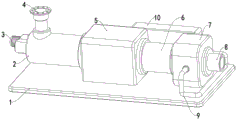
Fig. 1 is a schematic view of the overall structure of the present invention.
Fig. 2 is a schematic structural view of the heat dissipation cold row of the present invention.
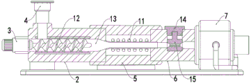
Fig. 3 is a schematic view of the overall internal structure of the present invention.
Fig. 4 is a schematic view (enlarged view) of the internal structure of the coolant circulation box of the present invention.
In the figure: 1. a fixing plate; 2. heating a tube; 3. a power mechanism; 4. a feed port; 5. a heating mechanism; 6. forming a pipeline; 7. a cooling tank; 8. a discharge port; 9. a circulating water pipe; 10. heat dissipation cold rows; 11. heating the threaded pipe; 12. a screw; 13. an extrusion chamber; 14. a sealing cover; 15. forming a built-in tool; 16. a coolant circulation tank; 17. a contact plate.
Detailed Description
The technical solutions in the embodiments of the present invention will be described clearly and completely with reference to the accompanying drawings in the embodiments of the present invention, and it is obvious that the described embodiments are only some embodiments of the present invention, not all embodiments.
Referring to fig. 1 to 4, the present invention provides an embodiment: a forming pipe tool comprises a fixing plate 1, a heating pipe 2 is installed at the upper end of the fixing plate 1, a power mechanism 3 is installed on the outer surface of one end of the heating pipe 2, a feeding port 4 is formed in the upper end face of the heating pipe 2, a heating mechanism 5 is installed at the other end of the heating pipe 2, a forming pipeline 6 is installed on one side of the heating mechanism 5, a cooling box 7 is installed on one side of the forming pipeline 6, a discharging port 8 is installed on one side of the cooling box 7, circulating water pipes 9 are installed on two sides of the discharging port 8, a heat dissipation cold row 10 is installed at one end of the cooling box 7, an extrusion bin 13 is arranged on the inner side of the heating pipe 2, a screw rod 12 is installed at one end of the extrusion bin 13, a heating threaded pipe 11 is installed on the inner side of the heating mechanism 5, heating effect is provided for, the built-in molding tool 15 is mounted on the lower end face of the sealing cover 14, the built-in molding tool 15 is taken out through the sealing cover 14 through the matching of the built-in molding tool 15 and the sealing cover 14, the replacement operation is carried out, the device can be used for machining molding pipes with various diameters, the cooling liquid circulation boxes 16 are arranged at two ends of the inner side of the cooling box 7, and the contact plate 17 is arranged on one side of each cooling liquid circulation box 16.
Further, the upper end face of the built-in molding tool 15 is completely attached to the sealing cover 14, the built-in molding tool 15 and the sealing cover 14 are fixed by threads, and the built-in molding tool 15 is taken out through the sealing cover 14 to be replaced, so that the device can process molding pipes with various diameters.
Further, the lower end face of the built-in molding tool 15 is completely attached to the inner wall of the molding pipeline 6, the built-in molding tool 15 and the molding pipeline 6 are fixed through a clamping groove, and the device can be rapidly molded through the effect of the built-in molding tool 15.
Further, a conveying pipeline is arranged on the inner side of the heating mechanism 5, a heating threaded pipe 11 spirally surrounds the outer surface of the conveying pipeline, and the heating function is provided for the device through the heating threaded pipe 11, so that the material is always in an ideal state.
Furthermore, one end of the screw 12 is connected with one side of the power mechanism 3, the screw 12 is meshed and fixed with the power mechanism 3 through a gear, and the extrusion bin 13 is matched with the screw 12 to provide power for the device to advance materials.
Further, extrude the one end in storehouse 13 and install heating mechanism, through the heating mechanism who extrudes 13 surfaces in storehouse, can increase the stirring efficiency of screw rod 12, make it can make the material stirring more even.
The working principle is as follows: when the device is used, the working state of an internal mechanism of the device is checked, the device is placed in a working area, the feeding port 4 is connected with external equipment, a power supply is switched on, the device is started, the screw 12 is driven to rotate through the power mechanism 3, materials entering the feeding port 4 are stirred, the materials are enabled to be in a semi-solidification state through the heating mechanism, the materials are extruded to the inner side of the heating mechanism 5 through the screw 12 and are heated through the heating threaded pipe 11, the state of the materials is guaranteed, then the materials are molded in the pipeline 6 through pressure, when the materials pass through the molding built-in tool 15, the materials are pressed into a specific shape through the shape inside of the molding built-in tool 15, the molding built-in tool 15 can be taken out through the sealing cover 14 for replacement operation, the device can be provided with molding pipe processing with various diameters, and the device can use more tubular processing, the finished product that processing was accomplished gets into the inboard of cooler bin 7 after, through circulating pipe 9 to the inside coolant liquid that carries of cooler bin 7, after 7 internal cycle a week of cooler bin, take back to the inside heat dissipation of heat dissipation cold row 10, recycle in proper order, carry out the rapid cooling shaping with the pipe fitting, and through installing contact plate 17 additional, can make the coolant liquid more quick take out the inside heat, install this mechanism additional, can shorten the shaping time of device product, thereby the manufacturing efficiency of device has been improved.
It is obvious to a person skilled in the art that the invention is not restricted to details of the above-described exemplary embodiments, but that it can be implemented in other specific forms without departing from the spirit or essential characteristics of the invention. The present embodiments are therefore to be considered in all respects as illustrative and not restrictive, the scope of the invention being indicated by the appended claims rather than by the foregoing description, and all changes which come within the meaning and range of equivalency of the claims are therefore intended to be embraced therein. Any reference sign in a claim should not be construed as limiting the claim concerned.
Claims (6)
1. The utility model provides a forming tube frock, includes fixed plate (1), its characterized in that: the heating pipe (2) is installed at the upper end of the fixing plate (1), a power mechanism (3) is installed on the outer surface of one end of the heating pipe (2), a feeding port (4) is arranged on the upper end face of the heating pipe (2), a heating mechanism (5) is installed at the other end of the heating pipe (2), a forming pipeline (6) is installed on one side of the heating mechanism (5), a cooling box (7) is installed on one side of the forming pipeline (6), a discharge port (8) is installed on one side of the cooling box (7), circulating water pipes (9) are installed on two sides of the discharge port (8), a heat dissipation cold bar (10) is installed at one end of the cooling box (7), an extrusion bin (13) is arranged on the inner side of the heating pipe (2), a screw rod (12) is installed at one end of the extrusion bin (13), and a heating threaded pipe (11) is, sealed lid (14) are installed to the up end of shaping pipeline (6), built-in frock of shaping (15) are installed to the lower terminal surface of sealed lid (14), the both ends of cooling tank (7) inboard all are provided with coolant liquid circulation case (16), one side of coolant liquid circulation case (16) is provided with contact plate (17).
2. A forming tube tooling as claimed in claim 1, wherein: the upper end face of the built-in molding tool (15) is completely attached to the sealing cover (14), and the built-in molding tool (15) is fixed to the sealing cover (14) through threads.
3. A forming tube tooling as claimed in claim 1, wherein: the lower end face of the built-in molding tool (15) is completely attached to the inner wall of the molding pipeline (6), and the built-in molding tool (15) is fixed with the molding pipeline (6) through a clamping groove.
4. A forming tube tooling as claimed in claim 1, wherein: the inner side of the heating mechanism (5) is provided with a conveying pipeline, and the heating threaded pipe (11) surrounds the outer surface of the conveying pipeline in a spiral shape.
5. A forming tube tooling as claimed in claim 1, wherein: one end of the screw rod (12) is connected with one side of the power mechanism (3), and the screw rod (12) is meshed and fixed with the power mechanism (3) through a gear.
6. A forming tube tooling as claimed in claim 1, wherein: and a heating mechanism is arranged at one end of the extrusion bin (13).
Priority Applications (1)
| Application Number | Priority Date | Filing Date | Title |
|---|---|---|---|
| CN201922000652.6U CN210969837U (en) | 2019-11-19 | 2019-11-19 | Forming pipe tool |
Applications Claiming Priority (1)
| Application Number | Priority Date | Filing Date | Title |
|---|---|---|---|
| CN201922000652.6U CN210969837U (en) | 2019-11-19 | 2019-11-19 | Forming pipe tool |
Publications (1)
| Publication Number | Publication Date |
|---|---|
| CN210969837U true CN210969837U (en) | 2020-07-10 |
Family
ID=71415695
Family Applications (1)
| Application Number | Title | Priority Date | Filing Date |
|---|---|---|---|
| CN201922000652.6U Active CN210969837U (en) | 2019-11-19 | 2019-11-19 | Forming pipe tool |
Country Status (1)
| Country | Link |
|---|---|
| CN (1) | CN210969837U (en) |
Cited By (1)
| Publication number | Priority date | Publication date | Assignee | Title |
|---|---|---|---|---|
| CN112172213A (en) * | 2020-10-17 | 2021-01-05 | 浙江吕氏管业有限公司 | Environment-friendly high-toughness CPVC cable protection pipe and processing method thereof |
-
2019
- 2019-11-19 CN CN201922000652.6U patent/CN210969837U/en active Active
Cited By (1)
| Publication number | Priority date | Publication date | Assignee | Title |
|---|---|---|---|---|
| CN112172213A (en) * | 2020-10-17 | 2021-01-05 | 浙江吕氏管业有限公司 | Environment-friendly high-toughness CPVC cable protection pipe and processing method thereof |
Similar Documents
| Publication | Publication Date | Title |
|---|---|---|
| CN210969837U (en) | Forming pipe tool | |
| CN210026226U (en) | Pipe extrusion die | |
| CN218855587U (en) | Aluminium system hose production is with annotating material device | |
| CN110919981A (en) | Injection mold with cooling device | |
| CN206415435U (en) | A kind of aluminium section material extruder | |
| CN214395293U (en) | High-strength anti-fission extrusion injection mold | |
| CN212312718U (en) | Screw extruder | |
| CN213648560U (en) | Processing cooling device of raw materials moulds plastics | |
| CN212385944U (en) | Extrusion head hot oil circulation heating injection molding machine | |
| CN211941962U (en) | Extruder for corrugated pipe production | |
| CN211616356U (en) | Injection mold system with temperature regulation function | |
| CN211441058U (en) | Enlarged double-wall corrugated pipe extrusion die | |
| CN210362356U (en) | Polyethylene pipe extrusion device | |
| CN211492052U (en) | Shaping mold for refractory material production | |
| CN211941839U (en) | Injection mold with cooling device | |
| CN114536643A (en) | Assembled injection moulding equipment who has anti-sticking dead function easy to assemble | |
| CN212554988U (en) | PE tubular product extrusion moulding machine | |
| CN205202074U (en) | Many feed inlets double screw extruder | |
| CN212949100U (en) | Double-screw plastic extruder heating device | |
| CN215320546U (en) | Double screw extruder cooling device for processing TPV elastomer | |
| CN215283227U (en) | Effectual mould is used in reagent bottle production of cooling | |
| CN214188348U (en) | Die for processing peripheral plastic sealing strip of automobile skylight | |
| CN211363203U (en) | Intelligent production equipment for industrial production | |
| CN210190477U (en) | Novel plastic extruder | |
| CN216941776U (en) | Cooling system of double-screw extruder |
Legal Events
| Date | Code | Title | Description |
|---|---|---|---|
| GR01 | Patent grant | ||
| GR01 | Patent grant |