CN210967056U - Positioning and drilling device for drilling machine - Google Patents
Positioning and drilling device for drilling machine Download PDFInfo
- Publication number
- CN210967056U CN210967056U CN201922039854.1U CN201922039854U CN210967056U CN 210967056 U CN210967056 U CN 210967056U CN 201922039854 U CN201922039854 U CN 201922039854U CN 210967056 U CN210967056 U CN 210967056U
- Authority
- CN
- China
- Prior art keywords
- drill bit
- positioner
- connecting rod
- work piece
- rotation
- Prior art date
- Legal status (The legal status is an assumption and is not a legal conclusion. Google has not performed a legal analysis and makes no representation as to the accuracy of the status listed.)
- Expired - Fee Related
Links
Images


Abstract
The utility model discloses a location drilling equipment for drilling machine, including base, sliding control frame, support column, drill bit mounting bracket, the quick positioner of work piece and drill bit positioner, fixed surface installs the sliding control frame on the base, the spout has been seted up in the sliding control frame, slidable mounting has the quick positioner of work piece in the spout, base upper surface one side fixed mounting has the support column, slidable mounting has the drill bit mounting bracket on the support column, drill bit mounting bracket bottom fixed mounting has drill bit positioner, and this utility model discloses the location that has realized work piece and drill bit when drilling man-hour is pressed from both sides tightly, has guaranteed the machining precision of work piece, has reduced the wearing and tearing rupture of drill bit simultaneously, has prolonged the life of drill bit, and simple structure, convenient operation, and the practicality is strong.
Description
Technical Field
The utility model relates to a machining location technical field specifically is a location drilling equipment for drilling machine.
Background
The drilling machine is a machine tool which mainly uses a drill bit to process holes on a workpiece, usually, the drill bit rotates to perform primary motion, the drill bit moves axially to perform feeding motion, the drilling machine is simple in structure, the processing precision is relatively low, through holes and blind holes can be drilled, special cutters can be replaced, the special cutters can be expanded, reamed and reamed, or tapping and other processing can be performed, the workpiece is fixed in the processing process, the cutters move, the centers of the cutters are aligned with the center of the hole, the cutters are rotated (the primary motion), and the drilling machine is suitable for production of parts with certain precision requirements on the distance between the holes. However, in the prior art, when the drill bit is used for deep hole machining, due to the fact that the drill bit is slender and poor in rigidity, positioning is difficult, the axis of a drilled hole is inclined due to the fact that a positioning device is not available, the position accuracy and the size accuracy of the hole are affected, the drill bit is prone to being broken, the drill bit is often screwed and matched with a nut through a bolt in the drilling process, the degrees of freedom of a workpiece in six directions are fixed, operation is very complex, and time and labor are wasted. To this end, we propose a positioning and drilling device for a drilling machine.
Disclosure of Invention
An object of the utility model is to provide a location drilling equipment for drilling machine to solve the problem that proposes among the above-mentioned background art.
In order to achieve the above object, the utility model provides a following technical scheme: the utility model provides a location drilling equipment for drilling machine, includes base, sliding control frame, support column, drill bit mounting bracket, the quick positioner of work piece and drill bit positioner, fixed surface installs the sliding control frame on the base, the spout has been seted up in the sliding control frame, slidable mounting has the quick positioner of work piece in the spout, fixed surface installs the support column on one side of the base, slidable mounting has the drill bit mounting bracket on the support column, drill bit mounting bracket bottom fixed mounting has drill bit positioner.
Preferably, quick positioner of work piece includes slide, pivot, single-end bolt, cooperation nut and locating plate, the rotation groove has been seted up to the symmetry in the slide both sides, the rotation groove bottom is rotated through the pivot and is connected with the single-end bolt, the meshing of single-end bolt outer wall is connected with the cooperation nut, fixed surface installs the locating plate in the middle part on the slide.
Preferably, drill bit positioner is including installation piece, parallel connecting rod, rotation connecting rod, three-point gangbar, connecting piece, spacing axis of rotation and clamping arc spare, drill bit mounting bracket bottom dispersion fixed mounting has three installation piece, installation piece middle part all rotates respectively through spacing axis of rotation and installs two parallel connecting rods and a three-point gangbar, two parallel connecting rod tip and three-point gangbar tip and middle part are connected, two through rotating connecting rod and connecting piece cooperation head and the tail rotation parallel connecting rod inboard equal fixed mounting has clamping arc spare.
Preferably, the rotating shaft is sleeved with a torsion spring.
Preferably, the single-head bolt threads are distributed at the outer end, and when the single-head bolt is in a certain degree with the top surface of the sliding seat, the starting point of the threads is lower than the height of the sliding seat.
Compared with the prior art, the beneficial effects of the utility model are that: installing a drill bit in the bottom of a drill bit mounting frame, starting the utility model, controlling a sliding control frame to enable a sliding seat to slide to a workpiece position along a sliding groove, placing the workpiece in a positioning plate or above the upper surface of the positioning plate, holding a single-head bolt at the bottom of a base to enable the bottom of the single-head bolt to rotate around a rotating shaft, enabling the single-head bolt to quickly form a degree with the top surface of the sliding seat under the action of a torsion spring, clamping two sides of the workpiece, manually screwing a matching nut to enable the matching nut to rotate downwards along the upper part of the single-head bolt, clamping the tops of two sides of the workpiece, limiting the degree of freedom of the left, the right, the upper and the lower parts of the workpiece, enabling the sliding seat to slide along the sliding groove to enable the position of the workpiece to be drilled to be under the drill bit, starting the drill bit to rotate downwards along a supporting column, enabling the outer end of a hand-held three-point linkage rod to rotate inwards, thereby drive the change slope that position and angle have taken place with interior tip rotation connecting rod in the middle part to drive parallel connecting rod leanin, make press from both sides tight arc piece and inwards press from both sides tightly simultaneously, restricted the position about the drill bit, take place the position when preventing that the drill bit from drilling and beat, thereby accomplish drilling processing, the utility model discloses the location that has realized work piece and drill bit when drilling processing is tight, has guaranteed the machining precision of work piece, has reduced the wearing and tearing rupture of drill bit simultaneously, has prolonged the life of drill bit, and simple structure, convenient operation, the practicality is strong.
Drawings
FIG. 1 is a schematic view of the overall structure of the present invention;
FIG. 2 is a schematic view of the assembly structure of the support rod of the present invention;
FIG. 3 is a schematic view of the structure of the vertical support rod of the present invention;
fig. 4 is a schematic view of the structure of the retractable isolation fence and the limiting rod of the present invention.
In the figure: 1. a base; 2. a sliding control frame; 3. a support pillar; 4. a drill mounting bracket; 5. a workpiece rapid positioning device; 6. a drill bit positioning device; 7. a chute; 8. a slide base; 9. a rotating shaft; 10. a single-headed bolt; 11. matching with a nut; 12. positioning a plate; 13. mounting blocks; 14. parallel connecting rods; 15. rotating the connecting rod; 16. a three-point linkage rod; 17. a connecting member; 18. a limiting rotating shaft; 19. clamping the arc-shaped piece; 20. the groove is rotated.
Detailed Description
The technical solutions in the embodiments of the present invention will be described clearly and completely with reference to the accompanying drawings in the embodiments of the present invention, and it is obvious that the described embodiments are only some embodiments of the present invention, not all embodiments. Based on the embodiments in the present invention, all other embodiments obtained by a person skilled in the art without creative work belong to the protection scope of the present invention.
Referring to fig. 1-4, the present invention provides a technical solution: the utility model provides a location drilling equipment for drilling machine, the on-line screen storage device comprises a base 1, sliding control frame 2, support column 3, drill bit mounting bracket 4, quick positioner 5 of work piece and drill bit positioner 6, 1 last fixed surface of base installs sliding control frame 2, slide groove 7 has been seted up in the sliding control frame 2, slidable mounting has quick positioner 5 of work piece in slide groove 7, 1 upper surface of base one side fixed mounting has support column 3, slidable mounting has drill bit mounting bracket 4 on support column 3, 4 bottom fixed mounting of drill bit mounting bracket has drill bit positioner 6.
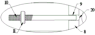
The workpiece quick positioning device 5 comprises a sliding seat 8, a rotating shaft 9, a single-head bolt 10, a matching nut 11 and a positioning plate 12, wherein rotating grooves 20 are symmetrically formed in two sides of the sliding seat 8, the bottom of each rotating groove 20 is rotatably connected with the single-head bolt 10 through the rotating shaft 9, the outer wall of each single-head bolt 10 is meshed with the matching nut 11, the positioning plate 12 is fixedly arranged in the middle of the upper surface of the sliding seat 8, and workpieces can be clamped quickly.
The drill bit positioning device 6 comprises an installation block 13, parallel connecting rods 14, a rotating connecting rod 15, a three-point linkage rod 16, a connecting piece 17, a limiting rotating shaft 18 and a clamping arc-shaped piece 19, the bottom of the drill bit installation frame 4 is dispersedly and fixedly provided with the three installation blocks 13, the middle part of the installation block 13 is respectively and rotatably provided with the two parallel connecting rods 14 and the three-point linkage rod 16 through the limiting rotating shaft 18, the end parts of the two parallel connecting rods 14 and the end parts of the three-point linkage rod 16 are in end-to-end rotating connection with the connecting piece 17 through the rotating connecting rod 15 in a matched mode, the clamping arc-shaped piece 19 is fixedly installed on the inner sides of the.
The rotating shaft 9 is sleeved with a torsion spring, so that the single-head bolt 10 and the top surface of the sliding seat 8 can quickly form an angle of 90 degrees or 0 degree.
The single-head bolt 10 is distributed at the outer end in a threaded mode, when the single-head bolt 10 and the top surface of the sliding seat 8 are 90 degrees, the starting point of the threads is lower than the height of the sliding seat 8, and therefore it is guaranteed that workpieces with different thicknesses can be clamped.
Installing a drill bit in the bottom of a drill bit mounting frame 4, starting the utility model, controlling a sliding control frame 2 to enable a slide seat 8 to slide towards a workpiece along a chute 7, placing the workpiece in a positioning plate 12 or above the upper surface of the positioning plate 12, holding a single-head bolt 10 at the bottom of a base 1 to enable the bottom of the single-head bolt 10 to rotate around a rotating shaft 9, enabling the single-head bolt 10 and the top surface of the slide seat 8 to quickly form 90 degrees under the action of a torsion spring, clamping two sides of the workpiece, then manually screwing a matching nut 11, enabling the matching nut 11 to rotate downwards along the upper part of the single-head bolt 10, clamping the tops of two sides of the workpiece to limit the left and right and up and down freedom degrees of the workpiece, enabling the slide seat 8 to slide along the chute 7 to enable the position of the workpiece to be drilled to be under the drill bit, starting the drill bit mounting frame 4 to slide downwards along a support column 3, enabling the drill bit to rotate, the quarter of the three-point linkage rod 16 uses the limiting rotating shaft 18 on the mounting block 13 as a rotating center to incline clockwise, so that the middle part and the inner end part are driven to rotate the connecting rod 15 to incline in a position and angle changing manner, the parallel connecting rods 14 are driven to incline inwards, the clamping arc-shaped part 19 is simultaneously clamped inwards, the left and right positions of the drill bit are limited, the position jumping of the drill bit during drilling is prevented, and the drilling processing is finished.
It is noted that, herein, relational terms such as first and second, and the like may be used solely to distinguish one entity or action from another entity or action without necessarily requiring or implying any actual such relationship or order between such entities or actions. Also, the terms "comprises," "comprising," or any other variation thereof, are intended to cover a non-exclusive inclusion, such that a process, method, article, or apparatus that comprises a list of elements does not include only those elements but may include other elements not expressly listed or inherent to such process, method, article, or apparatus.
Although embodiments of the present invention have been shown and described, it will be appreciated by those skilled in the art that changes, modifications, substitutions and alterations can be made in these embodiments without departing from the principles and spirit of the invention, the scope of which is defined in the appended claims and their equivalents.
Claims (5)
1. The utility model provides a location drilling equipment for drilling machine, includes base (1), sliding control frame (2), support column (3), drill bit mounting bracket (4), quick positioner of work piece (5) and drill bit positioner (6), its characterized in that: fixed surface installs sliding control frame (2) on base (1), spout (7) have been seted up in sliding control frame (2), slidable mounting has quick positioner of work piece (5) in spout (7), base (1) upper surface one side fixed mounting has support column (3), slidable mounting has drill bit mounting bracket (4) on support column (3), drill bit mounting bracket (4) bottom fixed mounting has drill bit positioner (6).
2. A pilot drilling assembly according to claim 1, wherein: quick positioner of work piece (5) includes slide (8), pivot (9), single-end bolt (10), cooperation nut (11) and locating plate (12), rotation groove (20) have been seted up to slide (8) bilateral symmetry, it is connected with single-end bolt (10) to rotate groove (20) bottom through pivot (9) rotation, single-end bolt (10) outer wall meshing is connected with cooperation nut (11), slide (8) upper surface middle part fixed mounting has locating plate (12).
3. A pilot drilling assembly according to claim 1, wherein: drill bit positioner (6) are including installation piece (13), parallel connecting rod (14), rotation connecting rod (15), three-point gangbar (16), connecting piece (17), spacing axis of rotation (18) and press from both sides tight arc (19), drill bit mounting bracket (4) bottom dispersion fixed mounting has three installation piece (13), installation piece (13) middle part all rotates respectively through spacing axis of rotation (18) and installs two parallel connecting rod (14) and a three-point gangbar (16), two parallel connecting rod (14) tip and three-point gangbar (16) tip and middle part are connected through rotating connecting rod (15) and connecting piece (17) cooperation end to end rotation, two parallel connecting rod (14) inboard equal fixed mounting has presss from both sides tight arc (19).
4. A pilot drilling assembly according to claim 2, wherein: and a torsion spring is sleeved on the rotating shaft (9).
5. A pilot drilling assembly according to claim 2, wherein: the single-head bolt (10) is distributed at the outer end in a threaded manner, and when the single-head bolt (10) and the top surface of the sliding seat (8) form an angle of 90 degrees, the starting point of the threads is lower than the height of the sliding seat (8).
Priority Applications (1)
| Application Number | Priority Date | Filing Date | Title |
|---|---|---|---|
| CN201922039854.1U CN210967056U (en) | 2019-11-23 | 2019-11-23 | Positioning and drilling device for drilling machine |
Applications Claiming Priority (1)
| Application Number | Priority Date | Filing Date | Title |
|---|---|---|---|
| CN201922039854.1U CN210967056U (en) | 2019-11-23 | 2019-11-23 | Positioning and drilling device for drilling machine |
Publications (1)
| Publication Number | Publication Date |
|---|---|
| CN210967056U true CN210967056U (en) | 2020-07-10 |
Family
ID=71414419
Family Applications (1)
| Application Number | Title | Priority Date | Filing Date |
|---|---|---|---|
| CN201922039854.1U Expired - Fee Related CN210967056U (en) | 2019-11-23 | 2019-11-23 | Positioning and drilling device for drilling machine |
Country Status (1)
| Country | Link |
|---|---|
| CN (1) | CN210967056U (en) |
Cited By (1)
| Publication number | Priority date | Publication date | Assignee | Title |
|---|---|---|---|---|
| CN116532693A (en) * | 2023-01-31 | 2023-08-04 | 高邮市永发机械有限公司 | Grinding wheel and processing equipment using same |
-
2019
- 2019-11-23 CN CN201922039854.1U patent/CN210967056U/en not_active Expired - Fee Related
Cited By (2)
| Publication number | Priority date | Publication date | Assignee | Title |
|---|---|---|---|---|
| CN116532693A (en) * | 2023-01-31 | 2023-08-04 | 高邮市永发机械有限公司 | Grinding wheel and processing equipment using same |
| CN116532693B (en) * | 2023-01-31 | 2024-01-09 | 高邮市永发机械有限公司 | Grinding wheel and processing equipment using same |
Similar Documents
| Publication | Publication Date | Title |
|---|---|---|
| CN102862011B (en) | Superhard cutting tool welding clamp | |
| KR20180057270A (en) | Vertical machining center remanufacturing assembly jig | |
| CN205834789U (en) | A kind of drilling machine | |
| CN210967056U (en) | Positioning and drilling device for drilling machine | |
| KR100906532B1 (en) | Drill stand | |
| CN106112086B (en) | A kind of automobile air conditioner accessories brill milling three-dimension process machine | |
| CN111069919A (en) | High-temperature gas cooled reactor tube plate weld thread machining equipment and machining process | |
| CN108356549A (en) | Numerically controlled lathe multi-purpose stand structure | |
| CN210208719U (en) | Novel drilling machine for machining hardware sheet metal parts | |
| CN111571754A (en) | Square hole machine and machining method thereof | |
| CN216263576U (en) | Double-end boring special plane | |
| EP1724038B1 (en) | Portable lathe | |
| CN108838445A (en) | A kind of fixture for the drilling of turning handle seat | |
| CN111618333B (en) | Boring device for rod head | |
| CN210231574U (en) | Multifunctional drilling machine | |
| CN114012442A (en) | Door closer machining device and door closer body machining process applied to same | |
| CN219052960U (en) | Drilling machine | |
| CN111546064A (en) | Special processing machine tool for waterwheel combined type water meter shell and gate valve | |
| CN220387984U (en) | Drilling machine fixture | |
| CN113275618B (en) | Machine tool and method for machining round holes of automobile body-in-white parts | |
| CN214867305U (en) | Multi-vehicle type slewing equipment | |
| CN211029020U (en) | Axial adjustable positioning device of numerical control machine tool | |
| CN212762218U (en) | Clamp for mechanical drilling machine | |
| CN215141268U (en) | But angle regulation's aviation spare part processing is with auxiliary fixtures | |
| CN215788305U (en) | Round piece clamping tool |
Legal Events
| Date | Code | Title | Description |
|---|---|---|---|
| GR01 | Patent grant | ||
| GR01 | Patent grant | ||
| CF01 | Termination of patent right due to non-payment of annual fee |
Granted publication date: 20200710 Termination date: 20201123 |
|
| CF01 | Termination of patent right due to non-payment of annual fee |