CN210940407U - Three-panel one-step integral blow molding mold of shared cabinet - Google Patents
Three-panel one-step integral blow molding mold of shared cabinet Download PDFInfo
- Publication number
- CN210940407U CN210940407U CN201921798051.8U CN201921798051U CN210940407U CN 210940407 U CN210940407 U CN 210940407U CN 201921798051 U CN201921798051 U CN 201921798051U CN 210940407 U CN210940407 U CN 210940407U
- Authority
- CN
- China
- Prior art keywords
- blowing chamber
- blow molding
- mould
- blowing
- chamber
- Prior art date
- Legal status (The legal status is an assumption and is not a legal conclusion. Google has not performed a legal analysis and makes no representation as to the accuracy of the status listed.)
- Active
Links
- 238000000071 blow moulding Methods 0.000 title claims abstract description 27
- 238000007664 blowing Methods 0.000 claims abstract description 60
- 239000007924 injection Substances 0.000 claims abstract description 13
- 239000011324 bead Substances 0.000 claims abstract description 9
- 238000001816 cooling Methods 0.000 claims abstract description 9
- 238000002347 injection Methods 0.000 claims abstract description 5
- 238000001746 injection moulding Methods 0.000 claims description 11
- 238000004321 preservation Methods 0.000 claims 1
- 238000007789 sealing Methods 0.000 abstract description 3
- 238000000465 moulding Methods 0.000 abstract 1
- 239000004033 plastic Substances 0.000 description 8
- 238000007493 shaping process Methods 0.000 description 5
- 239000000463 material Substances 0.000 description 4
- 238000009413 insulation Methods 0.000 description 3
- XLYOFNOQVPJJNP-UHFFFAOYSA-N water Substances O XLYOFNOQVPJJNP-UHFFFAOYSA-N 0.000 description 2
- 230000004075 alteration Effects 0.000 description 1
- 238000010102 injection blow moulding Methods 0.000 description 1
- 238000004519 manufacturing process Methods 0.000 description 1
- 230000004048 modification Effects 0.000 description 1
- 238000012986 modification Methods 0.000 description 1
- 238000006467 substitution reaction Methods 0.000 description 1
- 229920005992 thermoplastic resin Polymers 0.000 description 1
Images


Landscapes
- Moulds For Moulding Plastics Or The Like (AREA)
- Blow-Moulding Or Thermoforming Of Plastics Or The Like (AREA)
Abstract
The utility model discloses a trilateral board of sharing cabinet is whole blow molding mould once, including last mould, lower mould, the up end of lower mould is equipped with the blowing chamber, the blowing intracavity is equipped with twice parting bead, and the twice parting bead divide into first blowing chamber, second blowing chamber, third blowing chamber with the blowing chamber, the below in blowing chamber is equipped with the cooling chamber, even there are inlet tube and outlet pipe on the lateral wall in cooling chamber, the bottom in first blowing chamber, second blowing chamber, third blowing chamber all is equipped with the push pedal, the lower extreme of push pedal even has the cylinder, the lower terminal surface of going up the mould be equipped with blowing chamber complex clamp plate, the up end of going up the mould is equipped with injection and blowing mouth. The cabinet has the advantages that the cabinet can be integrally blow-molded with three panels of the shared cabinet at one time, so that the overall structure is very firm, the cabinet is stable, the three panels after molding are of an integrated structure, no gap exists between the panels, the sealing performance is improved, the stability is improved, and the cost is saved.
Description
Technical Field
The utility model relates to a trilateral board of sharing cabinet is whole blow molding mould once.
Background
The blow molding is that a tubular plastic parison obtained by extruding or injection molding thermoplastic resin is placed in a split mold while the parison is hot (or heated to a softened state), compressed air is introduced into the parison immediately after the mold is closed, so that the plastic parison is blown to cling to the inner wall of the mold, and various hollow products are obtained after cooling and demolding.
Three side walls of the shared cabinet are made by plastic injection molding, the current injection mold can only carry out injection molding on one side wall of the cabinet body, three sides of the shared cabinet cannot be formed at one time, each side needs to be mechanically connected after the single side is injected, manpower and material resources are consumed, the sealing performance of the manufactured cabinet body is poor, and the problem of insecure cabinet body can occur after the cabinet body is used for a long time.
SUMMERY OF THE UTILITY MODEL
In view of this, the utility model provides a trilateral board one-time whole blow molding mould of sharing cabinet.
In order to solve the technical problem, the utility model discloses a following technical scheme:
the utility model provides a trilateral board of sharing cabinet once whole blow molding mould, includes mould, lower mould, the up end of lower mould is equipped with the blowing chamber, the blowing intracavity is equipped with twice parting bead, and the twice parting bead divide into first blowing chamber, second blowing chamber, third blowing chamber with the blowing chamber, the below in blowing chamber is equipped with the cooling chamber, even there are inlet tube and outlet pipe on the lateral wall in cooling chamber, the bottom in first blowing chamber, second blowing chamber, third blowing chamber all is equipped with the push pedal, the lower extreme of push pedal even has the cylinder, the lower terminal surface of going up the mould be equipped with blowing chamber complex clamp plate, the up end of going up the mould is equipped with injection and blowing mouth.
According to the utility model discloses an embodiment, the outside of injection and blow molding mouth is equipped with the insulation cover, and the quantity of injection and blow molding mouth is three at least.
According to the utility model discloses an embodiment, the lower terminal surface of going up the mould is equipped with reference column, last locating hole, the lower terminal surface of lower mould is equipped with down reference column, lower locating hole, go up reference column and lower locating hole cooperation, go up the locating hole and cooperate with lower reference column.
According to the utility model discloses an embodiment, be equipped with the handle briquetting on the clamp plate.
According to an embodiment of the utility model, be equipped with the arch in the blowing intracavity.
According to the utility model discloses an embodiment, the both ends of lower mould are equipped with and are used for fixed connecting plate.
According to the utility model discloses an embodiment, four edges in first blowing chamber, second blowing chamber, third blowing chamber all are equipped with the push pedal, the below of lower mould is equipped with the roof, be connected through the ejector pin between roof and the push pedal, the lower extreme and the cylinder of roof are connected.
Additional aspects and advantages of the invention will be set forth in part in the description which follows and, in part, will be obvious from the description, or may be learned by practice of the invention.
1. The utility model discloses can once only with the whole blow molding of trilateral board of sharing cabinet for the overall structure is very firm, and the cupboard is steady, and trilateral board structure as an organic whole after the shaping does not have the gap between board and the board, has increased sealing performance, has improved stability, and integrated into one piece has improved work efficiency greatly moreover, can carry out mass production, has saved the cost.
2. The utility model discloses set up the parting bead with the blowing intracavity for the junction wall thickness between shaping back plate and the board is thinner, is convenient for buckle between board and the board, makes things convenient for later stage machine-shaping.
3. The utility model discloses set up the arch in the bed die, can not only increase the intensity of shaping back face, saved the material moreover.
4. The utility model discloses a plurality of push pedals have been realized releasing the blowing article after the shaping simultaneously, have avoided the damage to the product, the staff of being convenient for moreover takes the finished product.
Drawings
The above and/or additional aspects and advantages of the present invention will become apparent and readily appreciated from the following description of the embodiments, taken in conjunction with the accompanying drawings of which:
fig. 1 is a schematic view of the overall structure of the present invention;
FIG. 2 is a schematic structural view of an upper mold;
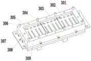
FIG. 3 is a schematic structural view of a lower mold;
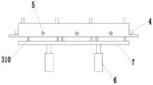
fig. 4 is a front view of the lower mold.
Reference numerals:
1-upper mould; 101-upper positioning columns; 102-upper positioning holes; 103-a platen; 104-handle pressing block; 2-injection and blow molding ports; 201-insulating sleeve; 3, lower die; 301-push plate; 302-a first blow mold cavity; 303-a second blow mold cavity; 304-parting strips; 305-a third blow mold cavity; 306-lower locating posts; 307-connecting plate; 308-lower positioning holes; 309-projection; 310-a mandril; 4-water outlet pipe; 5-water inlet pipe; 6-cylinder; 7-top plate.
Detailed Description
Reference will now be made in detail to embodiments of the present invention, examples of which are illustrated in the accompanying drawings, wherein like reference numerals refer to the same or similar elements or elements having the same or similar function throughout. The embodiments described below with reference to the drawings are exemplary only for the purpose of explaining the present invention, and should not be construed as limiting the present invention.
In the description of the present invention, it is to be understood that the terms "center", "longitudinal", "lateral", "length", "width", "thickness", "upper", "lower", "front", "rear", "left", "right", "vertical", "horizontal", "top", "bottom", "inner", "outer", "clockwise", "counterclockwise", "axial", "radial", "circumferential", and the like, indicate the orientation or positional relationship indicated based on the drawings, and are only for convenience of description and simplicity of description, and do not indicate or imply that the device or element referred to must have a particular orientation, be constructed and operated in a particular orientation, and therefore, should not be construed as limiting the present invention. Furthermore, a feature defined as "first" or "second" may explicitly or implicitly include one or more of that feature. In the description of the present invention, "a plurality" means two or more unless otherwise specified.
In the description of the present invention, it is to be noted that, unless otherwise explicitly specified or limited, the terms "mounted," "connected," and "connected" are to be construed broadly, and may be, for example, fixedly connected, detachably connected, or integrally connected; can be mechanically or electrically connected; they may be connected directly or indirectly through intervening media, or they may be interconnected between two elements. The specific meaning of the above terms in the present invention can be understood in specific cases to those skilled in the art.
In the first embodiment, the first step is,
referring to fig. 1-4 below, a trilateral board once integral blow molding mould of sharing cabinet, including last mould 1, lower mould 3, the up end of lower mould 3 is equipped with the blowing chamber, the blowing intracavity is equipped with twice parting bead 304, twice parting bead 304 divide into first blowing chamber 302 with the blowing chamber, second blowing chamber 303, third blowing chamber 305, the below in blowing chamber is equipped with the cooling chamber, even have inlet tube 5 and outlet pipe 4 on the lateral wall in cooling chamber, first blowing chamber 302, second blowing chamber 303, the bottom in third blowing chamber 305 all is equipped with push pedal 301, the lower extreme of push pedal 301 even has cylinder 6, the lower terminal surface of going up mould 1 is equipped with the clamp plate 103 with the blowing chamber complex, the up end of mould 1 is equipped with injection and blowing mouth 2.
In order to improve the heat insulation, a heat insulation sleeve 201 is provided outside the injection and blow molding port 2, and the number of the injection and blow molding ports 2 is at least three.
In order to ensure that the upper die 1 and the lower die 3 are tightly matched, the lower end surface of the upper die 1 is provided with an upper positioning column 101 and an upper positioning hole 102, the lower end surface of the lower die 3 is provided with a lower positioning column 306 and a lower positioning hole 308, the upper positioning column 101 is matched with the lower positioning hole 308, and the upper positioning hole 102 is matched with the lower positioning column 306.
Further, a handle pressing block 104 is arranged on the pressing plate 103.
Further, a protrusion 309 is disposed in the blow molding cavity.
Specifically, the lower die 3 is provided with connecting plates 307 at both ends thereof for fixation.
Specifically, four corners of the first blowing cavity 302, the second blowing cavity 303 and the third blowing cavity 305 are respectively provided with a push plate 301, a top plate 7 is arranged below the lower die 3, the top plate 7 is connected with the push plate 301 through a top rod 310, and the lower end of the top plate 7 is connected with the cylinder 6.
When the plastic injection blow molding device is used, the upper die 1 is matched with the lower die 3, the upper positioning column 101 is matched with the lower positioning hole 308, the upper positioning hole 102 is matched with the lower positioning column 306, a plastic parison is injected into a blow molding cavity through the injection and blow molding port 2, compressed air is introduced when the plastic parison is hot, the plastic parison is blown to cling to the inner wall of the die, the upper die is opened after the plastic parison is cooled, and the air cylinder 6 pneumatically pushes out a finished product through the push plate 301.
In particular, in the description of the present specification, reference to the description of the terms "one embodiment," "some embodiments," "illustrative embodiments," "an example," "a specific example," or "some examples" or the like means that a particular feature, structure, material, or characteristic described in connection with the embodiment or example is included in at least one embodiment or example of the present invention. In this specification, the schematic representations of the terms used above do not necessarily refer to the same embodiment or example. Furthermore, the particular features, structures, materials, or characteristics described may be combined in any suitable manner in any one or more embodiments or examples.
While embodiments of the present invention have been shown and described, it will be understood by those of ordinary skill in the art that: various changes, modifications, substitutions and alterations can be made to the embodiments without departing from the principles and spirit of the invention, the scope of which is defined by the claims and their equivalents.
Claims (7)
1. The utility model provides a trilateral board of sharing cabinet once whole blow molding mould which characterized in that: including last mould (1), lower mould (3), the up end of lower mould (3) is equipped with the blowing chamber, the blowing intracavity is equipped with twice parting bead (304), and twice parting bead (304) divide into first blowing chamber (302), second blowing chamber (303), third blowing chamber (305) with the blowing chamber, the below in blowing chamber is equipped with the cooling chamber, even have inlet tube (5) and outlet pipe (4) on the lateral wall in cooling chamber, the bottom in first blowing chamber (302), second blowing chamber (303), third blowing chamber (305) all is equipped with push pedal (301), the lower extreme of push pedal (301) even has cylinder (6), the lower terminal surface of going up mould (1) is equipped with and blowing chamber complex clamp plate (103), the up end of going up mould (1) is equipped with injection and blowing mouth (2).
2. The three-panel one-time integral blow molding mold of the shared cabinet according to claim 1, characterized in that: the outer side of the injection and blow molding opening (2) is provided with a heat preservation sleeve (201), and the number of the injection and blow molding openings (2) is at least three.
3. The three-panel one-time integral blow molding mold of the shared cabinet according to claim 1, characterized in that: an upper positioning column (101) and an upper positioning hole (102) are arranged on the lower end face of the upper die (1), a lower positioning column (306) and a lower positioning hole (308) are arranged on the lower end face of the lower die (3), the upper positioning column (101) is matched with the lower positioning hole (308), and the upper positioning hole (102) is matched with the lower positioning column (306).
4. The three-panel one-time integral blow molding mold of the shared cabinet according to claim 1, characterized in that: and a handle pressing block (104) is arranged on the pressing plate (103).
5. The three-panel one-time integral blow molding mold of the shared cabinet according to claim 1, characterized in that: and a bulge (309) is arranged in the blow molding cavity.
6. The three-panel one-time integral blow molding mold of the shared cabinet according to claim 1, characterized in that: and connecting plates (307) for fixing are arranged at two ends of the lower die (3).
7. The three-panel one-time integral blow molding mold of the shared cabinet according to claim 1, characterized in that: four corners in first blowing chamber (302), second blowing chamber (303), third blowing chamber (305) all are equipped with push pedal (301), the below of lower mould (3) is equipped with roof (7), be connected through ejector pin (310) between roof (7) and push pedal (301), the lower extreme and the cylinder (6) of roof (7) are connected.
Priority Applications (1)
| Application Number | Priority Date | Filing Date | Title |
|---|---|---|---|
| CN201921798051.8U CN210940407U (en) | 2019-10-24 | 2019-10-24 | Three-panel one-step integral blow molding mold of shared cabinet |
Applications Claiming Priority (1)
| Application Number | Priority Date | Filing Date | Title |
|---|---|---|---|
| CN201921798051.8U CN210940407U (en) | 2019-10-24 | 2019-10-24 | Three-panel one-step integral blow molding mold of shared cabinet |
Publications (1)
| Publication Number | Publication Date |
|---|---|
| CN210940407U true CN210940407U (en) | 2020-07-07 |
Family
ID=71399110
Family Applications (1)
| Application Number | Title | Priority Date | Filing Date |
|---|---|---|---|
| CN201921798051.8U Active CN210940407U (en) | 2019-10-24 | 2019-10-24 | Three-panel one-step integral blow molding mold of shared cabinet |
Country Status (1)
| Country | Link |
|---|---|
| CN (1) | CN210940407U (en) |
-
2019
- 2019-10-24 CN CN201921798051.8U patent/CN210940407U/en active Active
Similar Documents
| Publication | Publication Date | Title |
|---|---|---|
| JP2847582B2 (en) | Production equipment for resin fuel tanks | |
| CN210940407U (en) | Three-panel one-step integral blow molding mold of shared cabinet | |
| CN108568960B (en) | Vapour-pressure type mould of drawing of patterns of being convenient for | |
| CN216127648U (en) | Flange plate injection mold with good sealing performance for water pump | |
| CN215242541U (en) | Injection mold capable of improving injection molding quality | |
| CN213082316U (en) | Quick demoulding blowing mould | |
| CN210651828U (en) | Blow mold capable of being cooled rapidly | |
| CN213733248U (en) | Time-saving plastic injection mold | |
| CN213321601U (en) | Extrusion opening die for variable cross-section sealing strip | |
| CN210552568U (en) | EVA secondary foaming forming machine convenient for mold stripping | |
| CN216373301U (en) | Inferior gram force is blow molding mould for lamp shade | |
| CN218429894U (en) | Mold core mold locking ring, mold core and mold core mold locking ring combined structure and injection mold | |
| CN216941723U (en) | Injection mold with high heat dissipation performance | |
| CN215943560U (en) | Injection mold of automobile sensor | |
| CN214645643U (en) | Cooling system of bottle blank mold | |
| CN217514416U (en) | A high-efficient forming die for plastic goods production | |
| CN214294198U (en) | Key type mold structure | |
| CN205705030U (en) | Bulk plastic box handle injection mould | |
| CN215550836U (en) | Blow molding mold for precision plastic packaging container | |
| CN220008778U (en) | Multipurpose film blowing mould | |
| CN216992964U (en) | Injection mold | |
| CN214562714U (en) | Scalable motormeter dish lower cover mould | |
| CN223161270U (en) | Multicavity injection mold | |
| CN222431568U (en) | A preform injection blow molding mold | |
| CN221834866U (en) | Injection mold for special-shaped parts |
Legal Events
| Date | Code | Title | Description |
|---|---|---|---|
| GR01 | Patent grant | ||
| GR01 | Patent grant | ||
| CP03 | Change of name, title or address | ||
| CP03 | Change of name, title or address |
Address after: Room 4, No. 698 Wulian Road, Yushan Town, Kunshan City, Suzhou City, Jiangsu Province, 215300 Patentee after: Kunshan Shenghaoxin Health Technology Co.,Ltd. Address before: 215000 room 2, 268 BoQing Road, Yushan Town, Kunshan City, Suzhou City, Jiangsu Province Patentee before: KUNSHAN SHENGHAOXIN PRECISION MOLDING PRODUCTS Co.,Ltd. |