CN210938260U - Axle housing milling surface drilling clamp - Google Patents
Axle housing milling surface drilling clamp Download PDFInfo
- Publication number
- CN210938260U CN210938260U CN201921931504.XU CN201921931504U CN210938260U CN 210938260 U CN210938260 U CN 210938260U CN 201921931504 U CN201921931504 U CN 201921931504U CN 210938260 U CN210938260 U CN 210938260U
- Authority
- CN
- China
- Prior art keywords
- seat
- axle housing
- clamping
- clamp
- guide rail
- Prior art date
- Legal status (The legal status is an assumption and is not a legal conclusion. Google has not performed a legal analysis and makes no representation as to the accuracy of the status listed.)
- Active
Links
Images


Landscapes
- Drilling And Boring (AREA)
Abstract
The utility model provides an axle housing mills a boring grab, include: the device comprises a base, two screw rod mechanisms, a first guide rail and two clamping mechanisms, wherein the first guide rail and the two clamping mechanisms are arranged on the base; the screw rod mechanism comprises a screw rod and a nut; clamping mechanism is including supporting slide, first tight piece of clamp, the tight piece of second clamp and first actuating cylinder, two the support slide sets up two respectively on the nut, be equipped with the perpendicular to on the support slide the spout that first guide rail extends, first tight piece of clamp is located the spout is terminal, the tight piece of second clamp can be followed the spout sets up with sliding on the support slide, first actuating cylinder is located support on the slide and its output with the tight piece fixed connection of second clamp. The utility model discloses an axle housing mills a boring grab tightly cliies the leaf spring seat of axle housing work piece through two clamping mechanism of hydro-cylinder drive, and need not that fixing fixture such as workman's manual regulation locating pin can realize that the quick clamp is tight to be changed.
Description
Technical Field
The utility model relates to an axle housing processing technology field, concretely relates to axle housing mills a boring grab.
Background
The axle housing is used for mounting a main speed reducer, a differential mechanism, a half shaft and a wheel assembly base body, and is mainly used for supporting and protecting the main speed reducer, the differential mechanism, the half shaft and the like.
When axle housing processing drilling, need press from both sides tightly fixed to it, current anchor clamps are installed on numerical control dividing head usually, and axle housing both ends centre bore passes through locating pin and screw location clamp tightly, needs manual control clamping degree for king pin hole and centre bore position degree are unstable, can only process an axle housing usually every day, and clamping work piece and change variety are all difficult moreover.
SUMMERY OF THE UTILITY MODEL
An object of the utility model is to overcome shortcoming and not enough among the prior art, provide an axle housing mills a boring grab.
An embodiment of the utility model provides an axle housing mills a boring grab, include: the device comprises a base, two screw rod mechanisms, a first guide rail and two clamping mechanisms, wherein the first guide rail and the two clamping mechanisms are arranged on the base; the screw rod mechanism comprises a screw rod and a nut, the two screw rods are respectively arranged on the base and positioned at two ends of the first guide rail, the axis of the screw rod is parallel to the first guide rail, and the nut is slidably sleeved on the screw rod; clamping mechanism is including supporting slide, first tight piece of clamp, the tight piece of second clamp and first actuating cylinder, two the support slide sets up two respectively on the nut, be equipped with the perpendicular to on the support slide the spout that first guide rail extends, first tight piece of clamp is located the spout is terminal, the tight piece of second clamp can be followed the spout sets up with sliding on the support slide, first actuating cylinder is located support on the slide and its output with the tight piece fixed connection of second clamp.
Compared with the prior art, the utility model discloses an axle housing mills a boring grab and tightly cliies the plate spring seat of axle housing work piece through two clamping mechanism of hydro-cylinder drive, and need not that the workman can realize the quick-witted tight change of clamp manually adjusting fixed fixture such as locating pin, can only process an axle housing to processing 4 ~ 5 axle housings now one day originally one day, greatly promoted production efficiency to make through the tight piece of clamp that can regulate and control the distance and to the screw mechanism who carries out the front and back adjustment to the tight piece position of clamp the utility model discloses a clamping mechanism can adapt to different axle housing model sizes.
Further, clamping mechanism still includes fixed clamp seat and the tight seat of slip clamp, fixed clamp seat set firmly in the spout is terminal, the tight seat of slip clamp can be followed the spout sets up with sliding on the support slide, first clamp piece detachably sets up on the fixed clamp seat, second clamp piece detachably sets up on the tight seat of slip clamp, the output of a driving cylinder with the tight seat fixed connection of slip clamp. Because the processing shapes of the plate spring seats of the axle housing workpiece are different, the quick-replacement clamping block can adapt to axle housings of various different models.
Further, a first inclined surface is arranged on one surface, facing the second clamping block, of the first clamping block, and the first inclined surface is inclined towards the second clamping block; and one surface of the second clamping block facing the first clamping block is provided with a second inclined surface which inclines towards the first clamping block. Because the shape unevenness of surface after the plate spring seat processing of axle housing work piece, in order to avoid axle housing work piece vibration when drilling, increase an inclined plane and make and press from both sides tight piece when pressing from both sides the inclined plane and can support unevenness's place to can produce a decurrent packing force, further fasten the axle housing work piece, avoid the holistic vibration of axle housing work piece.
The first auxiliary supporting mechanism comprises an auxiliary supporting seat, a second driving oil cylinder and a supporting rod, the auxiliary supporting seat is slidably arranged on the guide rail, a vertical channel with an opening at the top of the auxiliary supporting seat is arranged in the auxiliary supporting seat, the second driving oil cylinder is fixedly arranged in the auxiliary supporting seat, the second driving oil cylinder is provided with a push rod connected with the output end of the second driving oil cylinder, the push rod transversely penetrates through the inner wall of the vertical channel and extends into the vertical channel, the supporting rod slidably penetrates through the vertical channel, and one end of the supporting rod extends out of the top of the auxiliary supporting seat; when the push rod extends out, the tail end of the push rod is tightly pressed against the side wall of the supporting rod. When milling a drilling hole, the opening face of the hemispherical shell of the axle housing workpiece faces the horizontal direction, the axle housing workpiece is provided with a horizontally extending structure, and the first auxiliary supporting mechanism supports the bottom of the horizontally extending structure, so that the structure can be prevented from vibrating up and down.
Furthermore, the first auxiliary supporting mechanism further comprises a spring, the spring is arranged in the vertical channel, one end of the spring is abutted against the auxiliary supporting seat, and the other end of the spring is abutted against the end face of the supporting rod. Because the structure position that the level stretches out on the axle housing work piece of different models is different, through keeping the bracing piece tight in the top the structure that the level stretches out and the staff of being convenient for adjusts the position of bracing piece, and the bracing piece is pressed from both sides through the hydro-cylinder after the position is correct and is fixed.
The lute-shaped surface positioning mechanism comprises a lute-shaped surface positioning seat, a three-jaw chuck and a guide cover, the lute-shaped surface positioning seat is arranged on the base and located between the two clamping mechanisms, the three-jaw chuck is arranged at the top of the lute-shaped surface positioning seat, and the guide cover is arranged at the top of the three-jaw chuck. When the opening surface of the hemispherical shell of the axle housing workpiece faces the vertical direction, the lute hole plane of the axle housing is positioned through the lute surface positioning seat, and at the moment, the main body part of the axle housing workpiece is covered on the lute surface positioning seat.
Further, the lute surface positioning mechanism further comprises a calibration ring, and the calibration ring is arranged at the top of the lute surface positioning seat in a mode of surrounding the three-jaw chuck. The calibration ring can realize the coordinate of the axle housing workpiece to be rapidly determined, and the position can be conveniently confirmed when the plate spring seat is drilled.
Further, the lute-shaped surface positioning seat comprises a second guide rail, wherein the second guide rail is arranged on the base and is perpendicular to the first guide rail, and the lute-shaped surface positioning seat is slidably arranged on the second guide rail. The lute-shaped face positioning seat can be moved to an easy-to-clamp position before clamping the axle housing workpiece, so that a narrow clamping space is avoided, and the angular positioning accuracy of the rear axle housing workpiece is guaranteed.
Further, still including compressing tightly positioning mechanism, compressing tightly positioning mechanism includes location supporting seat, third driving cylinder, guide holder and pressure arm, the location supporting seat sets up on the base and be located first guide rail one side, third driving cylinder sets up on the location supporting seat and its output is flexible in vertical direction, the guide holder sets up on the location supporting seat, the middle part of pressure arm can set up with rotating on the vertical face on the guide holder, the one end of pressure arm with the output of third driving cylinder links to each other, the other end of pressure arm is followed location supporting seat one side is stretched out, works as when third driving cylinder upwards stretches out, the other end of pressure arm compresses tightly the work piece downwards. The axle housing workpiece is pressed by the lever principle, the axle housing workpiece can be avoided during loosening of the clamping mechanism so as to be clamped, and the pressing arm presses the workpiece during clamping.
The second auxiliary supporting mechanism comprises a fourth driving oil cylinder and a supporting block, the fourth driving oil cylinder is arranged on the base and located below the other end of the pressing arm, the output end of the fourth driving oil cylinder stretches in the vertical direction, the supporting block is arranged at the output end of the fourth driving oil cylinder, and when the fourth driving oil cylinder extends upwards, the supporting block upwards supports the workpiece tightly. The clamping rigidity is increased, and the axle housing workpiece avoids vibration caused by too long cantilevers on two sides of the workpiece.
In order to make the present invention more clearly understood, the following description will be made in conjunction with the accompanying drawings.
Drawings
Fig. 1 is a schematic structural view of an axle housing milling surface drilling fixture according to an embodiment of the present invention;
FIG. 2 is a cross-sectional view of the clamping mechanism of the axle housing milling face drilling fixture shown in FIG. 1 in a vertical plane;
FIG. 3 is a schematic view of the clamping slide of the clamping mechanism of FIG. 2;
FIG. 4 is a cross-sectional view of a first auxiliary support mechanism of the axle housing milling face drilling fixture shown in FIG. 1 in a vertical plane;
FIG. 5 is a cross-sectional view of the first auxiliary support mechanism of the axle housing milling face drilling fixture of FIG. 1 in another vertical plane;
fig. 6 is a schematic structural view of an axle housing milling surface drilling fixture according to another embodiment of the present invention;
fig. 7 is a schematic structural diagram of a lute surface positioning mechanism of the axle housing milling surface drilling fixture shown in fig. 6;
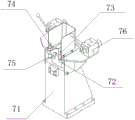
fig. 8 is a schematic structural diagram of a pressing and positioning mechanism of the axle housing milling surface drilling fixture shown in fig. 6.
Detailed Description
The technical solutions in the embodiments of the present invention will be described clearly and completely with reference to the accompanying drawings in the embodiments of the present invention, and it is obvious that the described embodiments are only some embodiments of the present invention, not all embodiments. Based on the embodiments in the present invention, all other embodiments obtained by a person skilled in the art without creative work belong to the protection scope of the present invention.
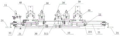
Please refer to fig. 1, which is a schematic structural diagram of an axle housing milling surface drilling fixture according to an embodiment of the present invention, the axle housing milling surface drilling fixture includes: the device comprises a base 10, two screw rod mechanisms, a first guide rail 30 arranged on the base 10 and two clamping mechanisms 40.
In this embodiment, the base 10 is plate-shaped, and the end supporting seat 11 for assisting in supporting the end of the axle housing is further fixedly arranged on one side of the base 10, so that a fulcrum is provided for the axle housing workpiece, and the subsequent clamping of the axle housing workpiece is facilitated.
The screw rod mechanism comprises a screw rod 21 and a nut 22, the screw rod 21 is arranged on the base 10 and located at two ends of the first guide rail 30, the axis of the screw rod 21 is parallel to the first guide rail 30, and the nut 22 is slidably sleeved on the screw rod 21. In some embodiments, a lead screw support 23 is used to fix two ends of the lead screw 21, and a rotating handle 24 is further provided at the end of the lead screw 21, so as to facilitate the operation of a worker. In some embodiments, since the nut 22 is not easily connected to the clamping mechanism 40, a nut seat 221 fixedly connected to the nut 22 may be further provided, and the nut seat 221 is used to connect to the clamping mechanism 40.
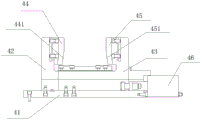
Referring to fig. 2, which is a cross-sectional view of the clamping mechanism of the axle housing milling surface drilling fixture shown in fig. 1, the clamping mechanism 40 includes a supporting slide seat 41, a fixed clamping seat 42, a sliding clamping seat 43, a first clamping block 44, a second clamping block 45 and a first driving cylinder 46, the two supporting slide seats 41 are respectively disposed on the two nuts 22, a sliding slot extending perpendicular to the first guide rail 30 is disposed on the supporting slide seat 41, the fixed clamping seat 42 is fixedly disposed at the end of the sliding slot, the sliding clamping seat 43 is slidably disposed on the supporting slide seat 41 along the sliding slot, the first clamping block 44 is detachably disposed on the fixed clamping seat 42, the second clamping block 45 is detachably disposed on the sliding clamping seat 43, and an output end of the first driving cylinder 46 is fixedly connected to the sliding clamping seat 43, the first clamping block 44 and the second clamping block 45 on the fixed clamping seat 42 and the sliding clamping seat 43 can be adapted to axle housings of different models through quick replacement. Referring to fig. 3, which is a schematic structural diagram of the clamping slide of the clamping mechanism shown in fig. 2, in this embodiment, the sliding slot is formed by two strip plates 411 erected on the supporting slide 41 in parallel, the sliding clamping seat 43 is erected above the strip plates 411, the bottom of the sliding clamping seat 43 extends into the sliding slot, the output end of the first driving cylinder 46 is fixedly connected with the sliding clamping seat 43 through a cylinder joint, and the first driving cylinder 46 pushes the bottom of the sliding clamping seat 43 to make the sliding clamping seat 43 slide along the sliding slot. Of course, in some embodiments, instead of using the fixed clamping seat 42 and the sliding clamping seat 43, the first clamping block 44 may be directly disposed at the end of the sliding slot, the second clamping block 45 may be slidably disposed on the supporting slide 41 along the sliding slot, and the first driving cylinder 46 is disposed on the supporting slide 41 and has an output end fixedly connected to the second clamping block 45.
In some embodiments, a first inclined surface 441 is provided on a face of the first clamping block 44 facing the second clamping block 45, the first inclined surface 441 being inclined toward the second clamping block 45; the second clamping block 45 is provided with a second inclined surface 451 on a surface facing the first clamping block 44, the second inclined surface 451 is inclined towards the first clamping block 44, in the embodiment, the first inclined surface 441 and the second inclined surface 451 are provided at a position close to the bottom of the first clamping block 44 and the second clamping block 45, so as to press a part protruding from a position close to the bottom of the side surface of the plate spring seat downwards. In some embodiments, serrations for increasing friction may be further provided on the first inclined surface 441 and the second inclined surface 451.
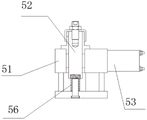
Referring to fig. 4 and 5, which are a cross-sectional view of a first auxiliary support mechanism of the axle housing milling surface drilling jig shown in fig. 1 on a vertical plane and a cross-sectional view of the first auxiliary support mechanism of the axle housing milling surface drilling jig shown in fig. 1 on another vertical plane, in some embodiments, the axle housing milling surface drilling jig further includes a first auxiliary support mechanism 50, the first auxiliary support mechanism 50 includes an auxiliary support base 51, a support rod 52 and a second driving cylinder 53, the auxiliary support base 51 is slidably disposed on the guide rail, in this embodiment, the auxiliary support base 51 is disposed on the first guide rail 30 through a sliding seat 511, a vertical channel opened at the top of the auxiliary support base 51 is disposed in the auxiliary support base 51, the support rod 52 is slidably disposed in the vertical channel, one end of the support rod extends from the top of the auxiliary support base 51, and the second driving cylinder 53 is fixedly disposed in the auxiliary support base 51, the second driving oil cylinder 53 is provided with a push rod 54 connected with an output end thereof, in this embodiment, a transverse channel is arranged on the auxiliary supporting seat 51, the transverse channel is communicated with a vertical channel, the push rod 54 transversely penetrates through the transverse channel and extends into the vertical channel, and when the second driving oil cylinder 53 controls the push rod 54 to extend, the tail end of the push rod 54 is tightly pressed against the side wall of the supporting rod 52. In some embodiments, the support rod 52 is further provided with a third inclined surface 521 which is inclined inward, the end of the push rod 54 abuts against the third inclined surface 521, the push rod 54 generates an upward inclined force on the third inclined surface 521, the horizontal force presses the support rod 52 against the inner wall of the vertical channel, and the vertical force pushes the support rod 52 upward, so that the top of the support rod 52 presses against the axle housing workpiece, and in order to prevent the support rod 52 from sliding out, a limit groove 522 may be provided on the outer wall of the support rod 52, and a limit screw 55 may be provided on the inner wall of the vertical channel of the auxiliary support seat 51 to limit the support rod 52 from sliding within a certain range. Preferably, first auxiliary stay mechanism 50 still includes spring 56, spring 56 sets up in the vertical passageway, its one end support in auxiliary stay 51, the other end support in the terminal surface of bracing piece 52, because need during actual operation with bracing piece 52 top tight axle housing work piece, but the utility model discloses a through the tight bracing piece 52 of hydro-cylinder top, it is too troublesome if need the manual work to keep bracing piece 52 at a correct position restart hydro-cylinder, makes the bracing piece 52 top upwards tightly through setting up spring 56 all the time, just so does not need the manual work to keep bracing piece 52 position. It should be noted that the auxiliary support mechanism may also be disposed on the clamping slide, and the auxiliary support seat 51 is fixedly disposed on the clamping slide and then slides through the clamping slide to drive the auxiliary support seat 51 to slide.
Please refer to fig. 6 and 7, which are a schematic structural diagram of an axle housing milling surface drilling fixture according to another embodiment of the present invention and a schematic structural diagram of an lute surface positioning mechanism of the axle housing milling surface drilling fixture shown in fig. 6. In some embodiments, still include lute face positioning mechanism 60, lute face positioning mechanism 60 includes lute face positioning seat 61, three-jaw chuck 62 and direction lid 63, lute face positioning seat 61 sets up on the base 10 and be located two between the clamping mechanism 40, three-jaw chuck 62 sets up lute face positioning seat 61 top, direction lid 63 sets up the top of three-jaw chuck 62, should establish behind the axle housing work piece through direction lid 63 on the lute face positioning seat 61, the axle housing work piece is blocked to three-jaw chuck 62 after stretching out. Preferably, the lute-shaped surface positioning mechanism 60 further comprises a calibration ring 64, the calibration ring 64 is arranged at the top of the lute-shaped surface positioning seat 61 in a mode of surrounding the three-jaw chuck 62, the lute-shaped hole plane of the axle housing workpiece is in contact with the calibration ring 64, and the calibration ring 64 can rapidly determine the coordinates of the axle housing workpiece, so that the position can be conveniently confirmed when the plate spring seat is drilled. Preferably, still include second guide rail 65, second guide rail 65 sets up on the base 10 and perpendicular to first guide rail 30, lute face positioning seat 61 sets up slidable on the second guide rail 65, before the axle housing work piece was pressed from both sides by foretell clamping mechanism 40, and lute face positioning seat 61 can move to the position that makes the axle housing work piece press from both sides the dress easily, has avoided narrow and small clamping space, can guarantee the degree of accuracy of rear axle housing work piece angular orientation through removing lute face positioning seat 61 simultaneously. It should be noted that, when the second guide rail 65 is provided, the first guide rail 30 may be interrupted into two parts to form two first guide rails 30, or certainly, the two first guide rails 30 may not be interrupted, the first guide rail 30 and the second guide rail 65 form a cross guide rail, and at this time, since the lute-shaped positioning seat 61 is provided in the middle of the base 10, if the first auxiliary supporting mechanism 50 is provided, the first auxiliary supporting mechanism 50 may be removed or moved to a proper position, in this embodiment, the first guide rail 30 also forms two interrupted guide rails. The lute hole center and the lute surface are the main design criteria of the axle housing product, and the lute surface positioning mechanism 60 is needed to position when a horizontal machining center is selected for machining.
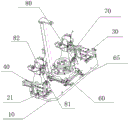
Please refer to fig. 8, which is a schematic structural diagram of the pressing and positioning mechanism of the axle housing milling surface drilling fixture shown in fig. 6. In some embodiments, the device further comprises a pressing and positioning mechanism 70, wherein the pressing and positioning mechanism 70 comprises a positioning support seat 71, a third driving oil cylinder 72, a guide seat 73 and a pressing arm 74, the positioning support seat 71 is disposed on the base 10 and located at one side of the first guide rail 30, the third driving oil cylinder 72 is arranged on the positioning support base 71 and the output end thereof extends and retracts in the vertical direction, the guide seat 73 is arranged on the positioning support seat 71, the middle part of the press arm 74 is rotatably arranged on the guide seat 73 on a vertical plane, one end of the pressure arm 74 is connected with the output end of the third driving oil cylinder 72, the other end of the pressure arm 74 extends out from one side of the positioning support seat 71, when the third driving cylinder 72 is extended upward, the other end of the pressing arm 74 presses the workpiece downward, and one end of the pressing arm 74 is lifted by the lever principle so that the other end of the pressing arm 74 is pressed. In some embodiments, a compression screw 75 or a pressure plate may be further disposed at the bottom of the other end of the pressing arm 74, and the axle housing workpiece is pressed by the compression screw 75 or the pressure plate. In some embodiments, a manual steering valve 76 is further disposed on the positioning support seat 71 to control an oil path communicated with the third driving cylinder 72.
In some embodiments, the second auxiliary supporting mechanism 80 is further included, the second auxiliary supporting mechanism 80 includes a fourth driving cylinder 81 and a supporting block 82, the fourth driving cylinder 81 is disposed on the base 10 and located below the other end of the pressing arm 74, an output end of the fourth driving cylinder 81 extends and retracts in the vertical direction, the supporting block 82 is disposed on an output end of the fourth driving cylinder 81, and when the fourth driving cylinder 81 extends upwards, the supporting block 82 pushes the workpiece upwards. In the present embodiment, the pressing and positioning mechanism 70 and the second auxiliary supporting mechanism 80 are disposed between the two clamping mechanisms 40, so as to avoid the two cantilevers of the workpiece from being too long, so that the middle suspension portion is too long and causes vibration during drilling, of course, the pressing and positioning mechanism 70 and the second auxiliary supporting mechanism 80 are determined according to the clamping position of the clamping mechanism 40, and if the cantilevers of the axle housing mechanism extend out of the clamping mechanism 40 for too long, the pressing and positioning mechanism 70 and the second auxiliary supporting mechanism 80 can be disposed outside the two clamping mechanisms 40.
In some embodiments, a hydraulic system is also included and is connected to each of the first drive ram 46, the second drive ram 53, the third drive ram 72, and the fourth drive ram 81.
The utility model discloses an axle housing mills a boring grab's whole clamping process can make the work piece pack into smoothly through the adjustment, and the location is accurate reliable, and the clamping rigidity is good, satisfies this kind of product batch production requirement.
Although embodiments of the present invention have been shown and described, it will be appreciated by those skilled in the art that changes, modifications, substitutions and alterations can be made in these embodiments without departing from the principles and spirit of the invention, the scope of which is defined in the appended claims and their equivalents.
Claims (10)
1. The utility model provides an axle housing mills a boring grab, its characterized in that includes: the device comprises a base, two screw rod mechanisms, a first guide rail and two clamping mechanisms, wherein the first guide rail and the two clamping mechanisms are arranged on the base;
the screw rod mechanism comprises a screw rod and a nut, the two screw rods are respectively arranged on the base and positioned at two ends of the first guide rail, the axis of the screw rod is parallel to the first guide rail, and the nut is slidably sleeved on the screw rod;
clamping mechanism is including supporting slide, first tight piece of clamp, the tight piece of second clamp and first actuating cylinder, two the support slide sets up two respectively on the nut, be equipped with the perpendicular to on the support slide the spout that first guide rail extends, first tight piece of clamp is located the spout is terminal, the tight piece of second clamp can be followed the spout sets up with sliding on the support slide, first actuating cylinder is located support on the slide and its output with the tight piece fixed connection of second clamp.
2. The axle housing milling face drilling clamp of claim 1, characterized in that: the clamping mechanism further comprises a fixed clamping seat and a sliding clamping seat, the fixed clamping seat is fixedly arranged at the tail end of the sliding groove, the sliding clamping seat can be arranged on the supporting sliding seat in a sliding mode, the first clamping block is detachably arranged on the fixed clamping seat, the second clamping block is detachably arranged on the sliding clamping seat, and the output end of the first driving oil cylinder is fixedly connected with the sliding clamping seat.
3. The axle housing milling face drilling clamp of claim 1, characterized in that: a first inclined surface is arranged on one surface, facing the second clamping block, of the first clamping block, and the first inclined surface inclines towards the second clamping block;
and one surface of the second clamping block facing the first clamping block is provided with a second inclined surface which inclines towards the first clamping block.
4. The axle housing milling face drilling clamp of claim 1, characterized in that: the first auxiliary supporting mechanism comprises an auxiliary supporting seat, a second driving oil cylinder and a supporting rod, the auxiliary supporting seat is slidably arranged on the guide rail, a vertical channel with an opening at the top of the auxiliary supporting seat is arranged in the auxiliary supporting seat, the second driving oil cylinder is fixedly arranged in the auxiliary supporting seat, the second driving oil cylinder is provided with a push rod connected with the output end of the second driving oil cylinder, the push rod transversely penetrates through the inner wall of the vertical channel and extends into the vertical channel, the supporting rod slidably penetrates through the vertical channel, and one end of the supporting rod extends out of the top of the auxiliary supporting seat; when the push rod extends out, the tail end of the push rod is tightly pressed against the side wall of the supporting rod.
5. The axle housing milling face drilling clamp of claim 4, wherein: the first auxiliary supporting mechanism further comprises a spring, the spring is arranged in the vertical channel, one end of the spring is abutted against the auxiliary supporting seat, and the other end of the spring is abutted against the end face of the supporting rod.
6. The axle housing milling face drilling clamp of claim 1, characterized in that: the lute-shaped surface positioning mechanism comprises a lute-shaped surface positioning seat, a three-jaw chuck and a guide cover, the lute-shaped surface positioning seat is arranged on the base and located between the two clamping mechanisms, the three-jaw chuck is arranged at the top of the lute-shaped surface positioning seat, and the guide cover is arranged at the top of the three-jaw chuck.
7. The axle housing milling face drilling clamp of claim 6, wherein: the lute surface positioning mechanism further comprises a calibration ring, and the calibration ring is arranged at the top of the lute surface positioning seat in a mode of surrounding the three-jaw chuck.
8. The axle housing milling face drilling clamp of claim 6, wherein: the lute-shaped face positioning seat is arranged on the second guide rail in a sliding mode.
9. The axle housing milling face drilling clamp of claim 6, wherein: still including compressing tightly positioning mechanism, it includes location supporting seat, third driving cylinder, guide holder and pressure arm to compress tightly positioning mechanism, the location supporting seat sets up on the base and be located first guide rail one side, third driving cylinder sets up on the location supporting seat and its output is flexible in vertical direction, the guide holder sets up on the location supporting seat, the middle part of pressing the arm can set up with rotating on vertical face on the guide holder, press the one end of arm with third driving cylinder's output links to each other, the other end of pressing the arm is followed location supporting seat one side is stretched out, works as when third driving cylinder upwards stretches out, the other end of pressing the arm compresses tightly the work piece downwards.
10. The axle housing milling face drilling clamp of claim 9, wherein: the pressing arm is arranged on the base, the second auxiliary supporting mechanism comprises a fourth driving oil cylinder and a supporting block, the fourth driving oil cylinder is arranged on the base and located below the other end of the pressing arm, the output end of the fourth driving oil cylinder stretches in the vertical direction, the supporting block is arranged at the output end of the fourth driving oil cylinder, and when the fourth driving oil cylinder stretches out upwards, the supporting block tightly supports the workpiece upwards.
Priority Applications (1)
| Application Number | Priority Date | Filing Date | Title |
|---|---|---|---|
| CN201921931504.XU CN210938260U (en) | 2019-11-08 | 2019-11-08 | Axle housing milling surface drilling clamp |
Applications Claiming Priority (1)
| Application Number | Priority Date | Filing Date | Title |
|---|---|---|---|
| CN201921931504.XU CN210938260U (en) | 2019-11-08 | 2019-11-08 | Axle housing milling surface drilling clamp |
Publications (1)
| Publication Number | Publication Date |
|---|---|
| CN210938260U true CN210938260U (en) | 2020-07-07 |
Family
ID=71399472
Family Applications (1)
| Application Number | Title | Priority Date | Filing Date |
|---|---|---|---|
| CN201921931504.XU Active CN210938260U (en) | 2019-11-08 | 2019-11-08 | Axle housing milling surface drilling clamp |
Country Status (1)
| Country | Link |
|---|---|
| CN (1) | CN210938260U (en) |
-
2019
- 2019-11-08 CN CN201921931504.XU patent/CN210938260U/en active Active
Similar Documents
| Publication | Publication Date | Title |
|---|---|---|
| CN209811796U (en) | Positioning device for machine tool machining | |
| CN110883582A (en) | Axle housing milling surface drilling clamp | |
| CN108032106B (en) | Efficient numerical control turning clamp and clamping method | |
| CN112077491A (en) | Axle housing accessory welding tool | |
| CN210938260U (en) | Axle housing milling surface drilling clamp | |
| CN212735125U (en) | Adjustable drilling fixing tool | |
| CN102430936A (en) | Self-adaptive blank outline clamping mechanism | |
| CN210360438U (en) | Shaper fixing device | |
| CN216178506U (en) | Parallel jaw for flexible clamping machine | |
| CN213827938U (en) | Multi-station machining center and clamping device thereof | |
| CN212095396U (en) | Lower connecting plate synchronous clamping tool for motorcycle steering mechanism | |
| CN113211143B (en) | Locating device for rough milling of inner side and outer side of upper lug and lower lug of steering knuckle | |
| CN209681978U (en) | A kind of Bidirectional flat-nose pliers | |
| CN201979324U (en) | Copper pipe clamp | |
| CN208913656U (en) | A kind of rough machined jig of valve body cylinder holes | |
| CN219725396U (en) | Adjustable machine tool workpiece clamp | |
| CN211805157U (en) | Positioning device of automatic sharpening machine for jaws | |
| CN220944169U (en) | Clamp for machine tool | |
| CN209754637U (en) | Drilling clamp for commercial vehicle brake | |
| CN219189422U (en) | CNC oil pressure frock | |
| CN110064869A (en) | A kind of roller shutter doorframe Automatic-clamping welder | |
| CN219901230U (en) | Workpiece positioning device of numerical control flat tongs | |
| CN211967136U (en) | Special clamp for grinding eccentric shaft | |
| CN217372082U (en) | Sheet metal working is with frock clamp who prevents lacquer and decrease | |
| CN215699868U (en) | A hold-down mechanism for part rough machining and parts machining frock thereof |
Legal Events
| Date | Code | Title | Description |
|---|---|---|---|
| GR01 | Patent grant | ||
| GR01 | Patent grant |