CN210919184U - Filter bypass valve capable of adjusting flow - Google Patents
Filter bypass valve capable of adjusting flow Download PDFInfo
- Publication number
- CN210919184U CN210919184U CN201921786225.9U CN201921786225U CN210919184U CN 210919184 U CN210919184 U CN 210919184U CN 201921786225 U CN201921786225 U CN 201921786225U CN 210919184 U CN210919184 U CN 210919184U
- Authority
- CN
- China
- Prior art keywords
- cylinder body
- inner cylinder
- strip
- shaped hole
- bypass valve
- Prior art date
- Legal status (The legal status is an assumption and is not a legal conclusion. Google has not performed a legal analysis and makes no representation as to the accuracy of the status listed.)
- Active
Links
Images


Abstract
The utility model discloses a filter bypass valve with adjustable flow, which relates to the field of filters, and in order to achieve the purpose, the technical proposal of the utility model comprises an outer cylinder body and an inner cylinder body; a sealing plate is arranged at the upper end of the outer cylinder body, the lower end of the outer cylinder body is arranged in an open manner, a plurality of outer strip-shaped holes are formed in the side wall of the outer cylinder body, and the outer strip-shaped holes are arranged along the axial direction; the upper end of the inner cylinder body is sealed, the lower port of the inner cylinder body is provided with a filter screen, and the side wall of the inner cylinder body is provided with an inner strip-shaped hole corresponding to the outer strip-shaped hole; a spring is arranged in the outer cylinder body, and two ends of the spring are respectively abutted to the lower surface of the sealing plate and the top of the inner cylinder body; when the inner cylinder body is positioned at the lowest part, the inner strip-shaped hole and the outer strip-shaped hole are staggered with each other; in the upward sliding process of the inner cylinder, the inner strip-shaped hole and the outer strip-shaped hole are gradually overlapped. Can avoid the machine oil that contains impurity to directly enter into each part, can block up after the filter core, filter machine oil in a certain extent, play the effect of interim protection.
Description
Technical Field
The utility model relates to a but flow regulation's filter bypass valve mainly relates to the filter field.
Background
The oil filter is located in the engine lubricating system, the oil pump is located at the upstream, and each part needing lubrication in the engine is located at the downstream, and the oil filter is used for filtering harmful impurities in the oil from an oil pan, supplying clean oil to moving parts such as a crankshaft, a connecting rod, a camshaft, a supercharger, piston rings and the like, and playing roles of lubrication, cooling and washing, thereby prolonging the service life of the parts.
At present, an internal oil filter generally comprises a shell and a filter element, wherein an annular filter element is arranged in the shell, a first space is formed in the filter element, a second space is formed between the filter element and the inner wall of the shell, an oil inlet and an oil outlet are arranged below the shell, the oil inlet is communicated with the second space, oil is filtered by the filter element and then reaches the first space and flows out from the oil outlet, a bypass valve is arranged on the filter element, after the filter element in the oil filter reaches a certain service life, the filter element is blocked, the oil inlet amount is insufficient, the bypass valve is opened under the action of a certain pressure, the oil directly enters the first space without being filtered and flows out from the oil outlet, and larger particles in the oil directly enter parts needing to be lubricated in an engine through an oil outlet, so that the engine is damaged.
SUMMERY OF THE UTILITY MODEL
The utility model provides a not enough to above prior art, the utility model provides an adjustable flow's filter bypass valve can avoid the machine oil that contains impurity to directly enter into each part, can be after the filter core blocks up, filters machine oil in a certain extent, plays the effect of interim protection.
In order to achieve the above purpose, the technical scheme of the utility model is that: comprises an outer cylinder and an inner cylinder; a sealing plate is arranged at the upper end of the outer cylinder body, the lower end of the outer cylinder body is arranged in an open manner, a plurality of outer strip-shaped holes are formed in the side wall of the outer cylinder body, and the outer strip-shaped holes are arranged along the axial direction; the upper end of the inner cylinder body is sealed, the lower port of the inner cylinder body is provided with a filter screen, and the side wall of the inner cylinder body is provided with an inner strip-shaped hole corresponding to the outer strip-shaped hole; a spring is arranged in the outer cylinder, and two ends of the spring are respectively abutted to the lower surface of the sealing plate and the top of the inner cylinder; when the inner cylinder body is positioned at the lowest part, the inner strip-shaped hole and the outer strip-shaped hole are staggered with each other; in the process that the inner cylinder body slides upwards, the inner strip-shaped hole and the outer strip-shaped hole are overlapped gradually.
The technical principle and the beneficial effects of the utility model are as follows:
this scheme is used for on the filter, and is the same with traditional filter bypass valve's the scheme that sets up, and the lower extreme of the outer barrel is fixed with the bottom plate of filter core, can meet an urgent need to open when oil cleaner blocks up completely, guarantees that machine oil can in time supply with. The engine oil enters the inner part of the inner cylinder body from the lower port of the inner cylinder body and is then discharged from the outer strip-shaped hole.
When the pressure of bypass valve lower part increases, the elasticity of spring will be overcome upwards to pressure, barrel rebound in the promotion, and when interior barrel rebound, outer bar hole and interior bar hole will coincide gradually, just can provide the passageway and supply machine oil to flow to the outside after outer bar hole and the coincidence of interior bar hole, according to the regional size that the size of pressure can automatic coincidence, because pressure is big more, interior barrel gliding distance must be far away more, and the machine oil passageway that the coincidence formed is also big more.
Because the lower port of barrel is equipped with the filter screen including, consequently the machine oil of including the barrel must filter the ability through the filter screen, avoids the machine oil that contains impurity directly to enter into each part, can block up after the filter core, filters machine oil in a certain extent, plays the effect of interim protection.
Preferably, the shrouding is equipped with the slide opening, the top of interior barrel is equipped with the traveller, the traveller upwards with slide opening sliding fit can make interior barrel more stable slip in outer barrel through the traveller.
Preferably, the upper portion of traveller is equipped with the stopper of avoiding the traveller to the slippage downwards, can avoid the traveller slippage through the stopper.
Preferably, the spring is sleeved on the sliding column, so that the spring support stability can be improved.
Preferably, the inside of interior barrel is equipped with the magnetism post, can adsorb the iron fillings in the machine oil through the magnetism post.
Preferably, the interior top of shrouding is equipped with the holding tank, the upper end of spring is fixed in the tank bottom of holding tank through setting up the holding tank, avoids holding the spring, avoids the spring to have no department to hold in the compression, and the compression stroke exceeds the stroke limit of spring.
Drawings
In order to more clearly illustrate the embodiments of the present invention or the technical solutions in the prior art, the drawings required for the description of the embodiments will be briefly introduced below, and it is obvious that the drawings in the following description are only three of the embodiments of the present invention, and for those skilled in the art, other drawings can be obtained according to these drawings without creative efforts.
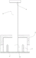
Fig. 1 is a schematic structural diagram of an embodiment of the present invention;
fig. 2 is a schematic view of an outer cylinder according to an embodiment of the present invention;
fig. 3 is a schematic view of the inner cylinder according to the embodiment of the present invention.
Wherein, outer barrel 1, interior barrel 2, traveller 3, stopper 4, spring 5, spout 6, interior bar hole 7, holding tank 8, filter screen 9, bottom plate 10, outer bar hole 11, magnetism post 12.
Detailed Description
The technical solutions of the present invention will be described clearly and completely with reference to the accompanying drawings, and it is to be understood that the described embodiments are merely preferred embodiments of the present invention, rather than all embodiments. Based on the embodiments in the present invention, all other embodiments obtained by a person skilled in the art without creative work belong to the protection scope of the present invention.
Examples
This scheme is used for on the filter, and is the same with traditional filter bypass valve's the scheme that sets up, and the lower extreme of barrel 1 is fixed with the bottom plate 10 of filter core outward, can meet an urgent need to open when oil cleaner blocks up completely, guarantees that machine oil can in time supply with. The engine oil enters the interior of the inner cylinder 2 from the lower port of the inner cylinder 2 and is then discharged from the outer strip-shaped hole 11.
As shown in fig. 1, the embodiment of the present invention includes an outer cylinder 1 and an inner cylinder 2; the upper end of the outer cylinder body 1 is provided with a sealing plate, and the sealing plate is provided with a sliding hole.
The lower extreme of outer barrel 1 is uncovered to be set up, the lateral wall of outer barrel 1 is equipped with a plurality of outer bar holes 11, outer bar hole 11 moves towards the setting along the axial.
The setting is sealed to 2 upper ends of interior barrel, the lower port of interior barrel 2 is equipped with filter screen 9, the lateral wall of interior barrel 2 corresponds outer bar hole 11 is equipped with interior bar hole 7. The top of interior barrel 2 is equipped with traveller 3, traveller 3 upwards with slide opening sliding fit can make interior barrel 2 more stable slip in outer barrel 1 through traveller 3. The upper portion of traveller 3 is equipped with the stopper 4 of avoiding traveller 3 slippage downwards, can avoid traveller 3 slippage through stopper 4. The inside of interior barrel 2 is equipped with magnetism post 12, can adsorb the iron fillings in the machine oil through magnetism post 12.
Be equipped with spring 5 in the outer barrel 1, spring 5's both ends support respectively to lean on to the lower surface of shrouding with the top of interior barrel 2. The interior top of shrouding is equipped with holding tank 8, the upper end of spring 5 is fixed in holding tank 8's tank bottom avoids holding spring 5 through setting up holding tank 8, avoids spring 5 to have no department to hold in the compression, avoids the compression stroke to exceed spring 5's stroke limit. The spring 5 is sleeved on the sliding column 3, so that the support stability of the spring 5 can be improved.
When the pressure of the lower part of the bypass valve is increased, the pressure overcomes the elastic force of the spring 5 upwards to push the inner cylinder 2 to move upwards, when the inner cylinder 2 moves upwards, the outer strip-shaped hole 11 and the inner strip-shaped hole 7 are overlapped gradually, the size of an area capable of being automatically overlapped is large according to the pressure, the larger the pressure is, the longer the upward sliding distance of the inner cylinder 2 is inevitably, and the larger the engine oil channel formed by overlapping is.
Because the lower port of interior barrel 2 is equipped with filter screen 9, consequently the machine oil of counting into interior barrel 2 must filter through filter screen 9 and go on, avoids the machine oil that contains impurity directly to enter into each part, can block up after the filter core, filters machine oil in certain extent, plays the effect of interim protection.
The outer cylinder body 1 and the inner cylinder body 2 can axially slide and cannot be in circumferential rotation fit, specifically, a sliding groove 6 is axially arranged on the inner wall in the outer cylinder body, and a protrusion is arranged on the outer wall of the inner cylinder body 2 corresponding to the sliding groove 6.
The above description is only a preferred embodiment of the present invention, and should not be taken as limiting the invention, and any modifications, equivalent replacements, improvements, etc. made within the spirit and principle of the present invention should be included in the protection scope of the present invention.
Claims (6)
1. The filter bypass valve capable of adjusting the flow is characterized by comprising an outer cylinder (1) and an inner cylinder (2);
a sealing plate is arranged at the upper end of the outer cylinder body (1), the lower end of the outer cylinder body (1) is arranged in an open mode, a plurality of outer strip-shaped holes (11) are formed in the side wall of the outer cylinder body (1), and the outer strip-shaped holes (11) are arranged along the axial direction;
the upper end of the inner cylinder (2) is sealed, the lower port of the inner cylinder (2) is provided with a filter screen (9), and the side wall of the inner cylinder (2) is provided with an inner strip-shaped hole (7) corresponding to the outer strip-shaped hole (11);
a spring (5) is arranged in the outer cylinder (1), and two ends of the spring (5) are respectively abutted against the lower surface of the sealing plate and the top of the inner cylinder (2);
when the inner cylinder (2) is positioned at the lowest part, the inner strip-shaped hole (7) and the outer strip-shaped hole (11) are staggered; in the upward sliding process of the inner cylinder body (2), the inner strip-shaped hole (7) and the outer strip-shaped hole (11) are gradually overlapped.
2. A variable flow filter bypass valve as defined in claim 1, wherein: the shrouding is equipped with the slide opening, the top of interior barrel (2) is equipped with traveller (3), traveller (3) upwards with slide opening sliding fit.
3. A variable flow capacity filter bypass valve as claimed in claim 2, wherein: and the upper part of the sliding column (3) is provided with a limiting block (4) for preventing the sliding column (3) from slipping downwards.
4. A variable flow capacity filter bypass valve as claimed in claim 2, wherein: the spring (5) is sleeved on the sliding column (3).
5. A variable flow filter bypass valve as defined in claim 1, wherein: the inner cylinder body (2) is internally provided with a magnetic column (12).
6. A variable flow filter bypass valve as defined in claim 1, wherein: the interior top of shrouding is equipped with holding tank (8), the upper end of spring (5) is fixed in the tank bottom of holding tank (8).
Priority Applications (1)
| Application Number | Priority Date | Filing Date | Title |
|---|---|---|---|
| CN201921786225.9U CN210919184U (en) | 2019-10-23 | 2019-10-23 | Filter bypass valve capable of adjusting flow |
Applications Claiming Priority (1)
| Application Number | Priority Date | Filing Date | Title |
|---|---|---|---|
| CN201921786225.9U CN210919184U (en) | 2019-10-23 | 2019-10-23 | Filter bypass valve capable of adjusting flow |
Publications (1)
| Publication Number | Publication Date |
|---|---|
| CN210919184U true CN210919184U (en) | 2020-07-03 |
Family
ID=71366394
Family Applications (1)
| Application Number | Title | Priority Date | Filing Date |
|---|---|---|---|
| CN201921786225.9U Active CN210919184U (en) | 2019-10-23 | 2019-10-23 | Filter bypass valve capable of adjusting flow |
Country Status (1)
| Country | Link |
|---|---|
| CN (1) | CN210919184U (en) |
Cited By (1)
| Publication number | Priority date | Publication date | Assignee | Title |
|---|---|---|---|---|
| CN115110916A (en) * | 2022-07-25 | 2022-09-27 | 中国石油化工股份有限公司 | Pressure-adjustable vortex tube |
-
2019
- 2019-10-23 CN CN201921786225.9U patent/CN210919184U/en active Active
Cited By (1)
| Publication number | Priority date | Publication date | Assignee | Title |
|---|---|---|---|---|
| CN115110916A (en) * | 2022-07-25 | 2022-09-27 | 中国石油化工股份有限公司 | Pressure-adjustable vortex tube |
Similar Documents
| Publication | Publication Date | Title |
|---|---|---|
| CN210919184U (en) | Filter bypass valve capable of adjusting flow | |
| CN202250303U (en) | Oil-gas separator with pressure device for ventilation of engine crankcase | |
| CN208900153U (en) | A kind of two-layer magnetic filtering oil filter | |
| CN102537640B (en) | High-efficiency combined oil filter | |
| CN107816375B (en) | Oil-gas separator for side air intake of engine | |
| CN211474205U (en) | Multi-stage filter bypass valve | |
| CN204371444U (en) | The fluid filter of internal-combustion engine | |
| CN108150242A (en) | A kind of high efficiency oil filter | |
| CN201513251U (en) | Labyrinth type valve chamber cover shell | |
| CN207974903U (en) | Fuel preliminary filter | |
| CN207905882U (en) | A kind of engine oil grid | |
| CN210919174U (en) | Filter bypass valve with graded adjustment | |
| CN206957781U (en) | Secondary protection oil filter | |
| CN207620873U (en) | Engine side air inlet gs-oil separator | |
| CN206338098U (en) | Serial machine oil rectifier | |
| CN208010422U (en) | A kind of high efficiency oil filter | |
| CN106762021A (en) | Serial machine oil rectifier | |
| CN201433800Y (en) | Motorcycle engine secondary filter mechanism | |
| CN205858439U (en) | A kind of oil filter | |
| CN108019251A (en) | Magnetic filter element oil filter | |
| CN205001011U (en) | Novel engine oil filter | |
| CN206785532U (en) | Fuel filter | |
| CN109026472A (en) | A kind of filter shunted | |
| CN207513652U (en) | A kind of machine oil filter core device for removing engine oil channel residual waste oil | |
| CN205089417U (en) | Environment -friendly oil cleaner |
Legal Events
| Date | Code | Title | Description |
|---|---|---|---|
| GR01 | Patent grant | ||
| GR01 | Patent grant |