CN210885655U - Sewage treatment device capable of removing residues and waste gas - Google Patents
Sewage treatment device capable of removing residues and waste gas Download PDFInfo
- Publication number
- CN210885655U CN210885655U CN201921768207.8U CN201921768207U CN210885655U CN 210885655 U CN210885655 U CN 210885655U CN 201921768207 U CN201921768207 U CN 201921768207U CN 210885655 U CN210885655 U CN 210885655U
- Authority
- CN
- China
- Prior art keywords
- fixed
- settling tank
- water
- net rack
- filter screen
- Prior art date
- Legal status (The legal status is an assumption and is not a legal conclusion. Google has not performed a legal analysis and makes no representation as to the accuracy of the status listed.)
- Expired - Fee Related
Links
Images


Landscapes
- Filtration Of Liquid (AREA)
Abstract
The utility model relates to a sewage treatment device capable of removing residue and waste gas, belonging to the technical field of sewage treatment, wherein a water inlet is communicated with the upper end of a residue treatment box; two first placing plates are respectively fixed on the left side wall and the right side wall in the residue treatment box; a first sliding rail is fixed on the first placing plate, and a first sliding block is arranged on the first sliding rail in a sliding manner; the first net rack is fixed on the first sliding block; the iron wire filter screen is fixed in the first net rack; the fine sand filter screen is fixed in the second net rack; the front side of the residue treatment box is screwed with a box door by a hinge; the bottom of the residue treatment box is provided with a water outlet in a through manner, four corners of the bottom of the residue treatment box are respectively fixed with support legs, and the four support legs are fixed on the sedimentation box; the double filtration of iron wire filter screen and fine sand filter screen for the residue is clear away more thoroughly, and iron wire filter screen and fine sand filter screen telescopic clearance improve sewage treatment's efficiency.
Description
Technical Field
The utility model relates to a sewage treatment technical field, concretely relates to can get rid of sewage treatment ware of residue and waste gas.
Background
Modern society's sewage composition is various, and not all sewage all need all pass through complicated filtration purification, and the most structure of current sewage treatment device is huge, and the structure is complicated, and sewage treatment device power consumption is high, has consumed a large amount of energy when handling the single sewage of composition, consequently, to the sewage of single composition, proposes a sewage treatment ware that can get rid of residue and waste gas.
SUMMERY OF THE UTILITY MODEL
The utility model aims to provide a sewage treatment device capable of removing residues and waste gas aiming at the defects and shortcomings of the prior art, the double filtration of the iron wire filter screen and the fine sand filter screen ensures that the residues are removed more thoroughly, and the iron wire filter screen and the fine sand filter screen can be pulled out and cleaned; waste gas purifies in the spiral pipe, and the inside area of spiral pipe is big, helps waste gas purification, improves sewage treatment's efficiency.
In order to achieve the above object, the utility model adopts the following technical scheme: the device comprises a water inlet, a residue treatment box, a first placing plate, a first slide rail, a first slide block, a first net rack, an iron wire filter screen, a second placing plate, a second slide rail, a second slide block, a second net rack, a fine sand filter screen, a box door, a water outlet, support legs, a settling box, an air suction pump, a first air duct, a second air duct, a spiral tube, active carbon, an air outlet, a first support, a second support, a water pump, a first water pipe, a second water pipe, a motor, a rotating shaft, a third support and an observation window; the water inlet is communicated with the upper end of the residue treatment box; two first placing plates are respectively fixed on the left side wall and the right side wall in the residue treatment box; a first sliding rail is fixed on the first placing plate, and a first sliding block is arranged on the first sliding rail in a sliding manner; the first net rack is fixed on the first sliding block; the iron wire filter screen is fixed in the first net rack; two second placing plates are respectively fixed on the left side wall and the right side wall in the residue treatment box; a second sliding rail is fixed on the second placing plate, and a second sliding block is arranged on the second sliding rail in a sliding manner; the second net rack is fixed on the second sliding block, and the second net rack is arranged below the first net rack; the fine sand filter screen is fixed in the second net rack; the front side of the residue treatment box is screwed with a box door by a hinge; the bottom of the residue treatment box is provided with a water outlet in a through manner, four corners of the bottom of the residue treatment box are respectively fixed with support legs, and the four support legs are fixed on the sedimentation box;
the air suction pump is fixed on the top plate of the settling tank; a first air duct is inserted and fixed at the inlet end of the settling tank, and the inlet end of the first air duct penetrates through the top plate of the settling tank and then is arranged in the settling tank; the outlet end of the air pump is fixedly provided with a second air duct in an inserting manner, the outlet end of the second air duct is fixedly connected with a spiral tube, and activated carbon is arranged in the spiral tube; an air outlet is fixedly inserted into the outlet end of the spiral pipe, a plurality of first supports are fixedly arranged at the lower end of the spiral pipe, and the lower ends of the first supports are fixedly arranged on a top plate of the settling tank;
a second bracket is fixed on the right side wall of the settling tank, a water pump is fixed on the second bracket, a first water pipe is inserted and fixed at the inlet end of the water pump, the inlet end of the first water pipe penetrates through the right side wall of the settling tank and then is arranged in the settling tank, and the first water pipe is a stainless steel metal hose; a second water pipe is inserted and fixed at the outlet end of the water pump; the motor is fixed on the second bracket; the rotating shaft is fixed on an output shaft of the motor, and the first water pipe is wound on the rotating shaft; the third bracket is fixed on the second bracket, and the front end of the rotating shaft is erected on the third bracket; the front end of the settling tank is provided with an observation window.
Furthermore, an ultraviolet disinfection lamp is fixed on the top plate of the settling box and is connected with an external power supply.
Furthermore, a first handle is fixed at the front end of the first net rack.
Furthermore, a second handle is fixed at the front end of the second net rack.
Furthermore, a fourth support is fixed on the left side wall of the settling tank, a dredge pump is fixed on the fourth support, a suction pipe is fixedly inserted into an inlet end of the dredge pump, the inlet end of the suction pipe penetrates through the left side wall of the settling tank and is arranged in the settling tank, and a horn head is fixed at the inlet end of the suction pipe; the outlet end of the dredge pump is inserted and fixed with a pipeline.
Furthermore, the inner surface of the bottom of the settling tank is inclined downwards from right to left; a third water pipe is fixed on the right side of the top plate of the settling box, and the inlet end of the third water pipe is connected with external tap water; a plurality of spray heads are fixed below the third water pipe in series.
After the structure is adopted, the utility model discloses beneficial effect does: the sewage treatment device capable of removing the residues and the waste gas, provided by the utility model, can remove the residues more thoroughly by double filtration of the iron wire filter screen and the fine sand filter screen, and the iron wire filter screen and the fine sand filter screen can be pulled out and cleaned; waste gas purifies in the spiral pipe, and the inside area of spiral pipe is big, helps waste gas purification, improves sewage treatment's efficiency.
Drawings
In order to more clearly illustrate the embodiments of the present invention or the technical solutions in the prior art, the drawings needed to be used in the description of the embodiments or the prior art will be briefly described below, it is obvious that the drawings in the following description are only some embodiments of the present invention, and for those skilled in the art, other drawings can be obtained according to these drawings without inventive exercise.
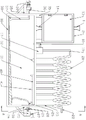
Fig. 1 is a schematic structural diagram of the present invention.
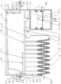
Fig. 2 is a schematic diagram of the internal structure of the present invention.
Fig. 3 is a sectional view taken along the plane a-a of fig. 1.
Fig. 4 is a schematic structural view of the iron wire filter screen of the present invention.
Fig. 5 is a schematic structural diagram of the fine sand filter screen of the present invention.
Fig. 6 is an enlarged view of a portion B of fig. 2.
Description of reference numerals:
the device comprises a water inlet 1, a residue treatment box 2, a first placing plate 3, a first slide rail 4, a first slide block 5, a first net rack 6, an iron wire filter screen 7, a second placing plate 8, a second slide rail 9, a second slide block 10, a second net rack 11, a fine sand filter screen 12, a box door 13, a water outlet 14, support legs 15, a settling box 16, an air suction pump 17, a first air guide pipe 18, a second air guide pipe 19, a spiral pipe 20, active carbon 21, an air outlet 22, a first support 23, a second support 24, a water pump 25, a first water pipe 26, a second water pipe 27, a motor 28, a rotating shaft 29, a third support 30, an observation window 31, an ultraviolet disinfection lamp 32, a first handle 33, a second handle 34, a fourth support 35, a sludge suction pump 36, a suction pipe 37, a horn head 38, a pipeline 39, a third water pipe 40 and a spray head 41.
Detailed Description
The present invention will be further described with reference to the accompanying drawings.
Referring to fig. 1 to 6, the present embodiment includes a water inlet 1, a residue treatment tank 2, a first placing plate 3, a first slide rail 4, a first slide block 5, a first net rack 6, an iron wire filter screen 7, a second placing plate 8, a second slide rail 9, a second slide block 10, a second net rack 11, a fine sand filter screen 12, a tank door 13, a water outlet 14, a support leg 15, a sedimentation tank 16, an air pump 17, a first air duct 18, a second air duct 19, a spiral tube 20, activated carbon 21, an air outlet 22, a first bracket 23, a second bracket 24, a water pump 25, a first water pipe 26, a second water pipe 27, a motor 28, a rotating shaft 29, a third bracket 30, an observation window 31, an ultraviolet disinfection lamp 32, a first handle 33, a second handle 34, a fourth bracket 35, a sludge suction pump 36, a suction pipe 37, a horn head 38, a pipeline 39, a third water pipe 40, and a spray head 41; the water inlet 1 is communicated with the upper end of the residue treatment box 2; the two first placing plates 3 are respectively fixed on the left side wall and the right side wall in the residue treatment box 2 through bolts; a first sliding rail 4 is fixedly welded on the first placing plate 3, and a first sliding block 5 is slidably arranged on the first sliding rail 4; the first net rack 6 is welded and fixed on the first sliding block 5; the iron wire filter screen 7 is fixed in the first net rack 6 through bolts; the iron wire filter screen 7 can filter large residues for rough filtration; the two second placing plates 8 are respectively fixed on the left side wall and the right side wall in the residue treatment box 2 through bolts; a second sliding rail 9 is fixedly welded on the second placing plate 8, and a second sliding block 10 is slidably arranged on the second sliding rail 9; the second net rack 11 is welded and fixed on the second sliding block 10, and the second net rack 11 is arranged below the first net rack 6; the fine sand filter screen 12 is fixed in the second net rack 11 through bolts; the fine sand filter screen 12 can filter smaller residues and floating objects for fine filtration; the front side of the residue treatment box 2 is screwed with a box door 13 by a hinge; after filtering, opening the box door 13, drawing out the first net rack 6 and the second net rack 11, and cleaning residues on the iron wire filter screen 7 and the fine sand filter screen 12; a water outlet 14 is formed in the bottom of the residue treatment box 2 in a penetrating manner, supporting legs 15 are fixed to four corners of the bottom of the residue treatment box 2 through bolts, and the four supporting legs 15 are fixed to a settling tank 16;
the air pump 17 is fixed on the top plate of the settling tank 16 through bolts; a first air duct 18 is inserted and fixed at the inlet end of the settling tank 16, and the inlet end of the first air duct 18 passes through the top plate of the settling tank 16 and then is arranged in the settling tank 16; a second air duct 19 is inserted and fixed at the outlet end of the air pump 17, the outlet end of the second air duct 19 is fixedly connected with a spiral tube 20, and activated carbon 21 is arranged in the spiral tube 20; an air outlet 22 is fixedly inserted into the outlet end of the spiral pipe 20, a plurality of first supports 23 are fixedly arranged at the lower end of the spiral pipe 20 through bolts, and the lower ends of the first supports 23 are fixedly arranged on the top plate of the settling tank 16 through bolts; mixing various components in the sewage together, easily fermenting to generate unpleasant waste gas, starting the air extraction pump 17, extracting the gas in the settling tank 16, introducing the gas into the spiral pipe 20, and discharging the waste gas components in the gas from the air outlet 22 after the waste gas components are absorbed by the activated carbon 21 in the spiral pipe 20;
a second bracket 24 is fixed on the right side wall of the settling tank 16 through bolts, a water pump 25 is fixed on the second bracket 24 through bolts, a first water pipe 26 is fixedly inserted into an inlet end of the water pump 25, an inlet end of the first water pipe 26 penetrates through the right side wall of the settling tank 16 and then is arranged in the settling tank 16, and the first water pipe 26 is a stainless steel metal hose; a second water pipe 27 is inserted and fixed at the outlet end of the water pump 25; the motor 28 is fixed on the second bracket 24 through bolts, and the model number of the motor 28 is 60 KTYZ; the rotating shaft 29 is fixedly welded on an output shaft of the motor 28, and the first water pipe 26 is wound on the rotating shaft 29; the third bracket 30 is welded and fixed on the second bracket 24, and the front end of the rotating shaft 29 is erected on the third bracket 30; the front end of the settling tank 16 is provided with an observation window 31; after being filtered by the iron wire filter screen 7 and the fine sand filter screen 12, the sewage enters the settling tank 16 from the water outlet 14 for settling, and the settling condition can be observed through the observation window 31; after the sedimentation is finished, starting the motor 28, adjusting the first water pipe 26 according to the height of the sedimented sludge, and preventing the outlet of the first water pipe 26 from touching the sludge; starting a water pump 25, pumping out the settled water, and discharging the water into a designated container through a second water pipe 27;
an ultraviolet disinfection lamp 32 is fixed on the top plate of the settling tank 16 through a bolt, the ultraviolet disinfection lamp 32 is connected with an external power supply, and the ultraviolet disinfection lamp 32 is turned on in the settling process to play a role in disinfection and sterilization;
a first handle 33 is welded and fixed at the front end of the first net rack 6, so that the first net rack 6 can be conveniently drawn out, and residues on the iron wire filter screen 7 can be cleaned;
a second handle 34 is welded and fixed at the front end of the second net rack 11, so that the second net rack 11 can be conveniently drawn out, and residues on the fine sand filter screen 12 can be cleaned;
a fourth bracket 35 is fixed on the left side wall of the settling tank 16 through bolts, a sludge suction pump 36 is fixed on the fourth bracket 35 through bolts, a suction pipe 37 is fixedly inserted into an inlet end of the sludge suction pump 36, the inlet end of the suction pipe 37 penetrates through the left side wall of the settling tank 16 and then is arranged in the settling tank 16, and a horn head 38 is fixedly welded on the inlet end of the suction pipe 37 to increase the contact area; a pipeline 39 is inserted and fixed at the outlet end of the dredge pump 36; after most of water is observed to be pumped out through the observation window 31, the water pump 25 is closed, the sludge pump 36 is started, sludge at the bottom of the box is sucked out and is discharged into a designated container through the pipeline 39;
the inner surface of the bottom of the settling tank 16 is inclined downwards from right to left; a third water pipe 40 is fixed on the right side of the top plate of the settling tank 16 through a bolt, and the inlet end of the third water pipe 40 is connected with external tap water; a plurality of spray heads 41 are fixed below the third water pipe 40 in series; when the sludge is sucked by the sludge suction pump 36, water flow is introduced into the third water pipe 40 and sprayed out by the spray head 41 to properly wash the bottom of the tank, and the sludge on the right side of the bottom of the settling tank 16 flows to the horn head 38 below the suction pipe 37 along an inclined angle, so that incomplete sludge removal is avoided.
The working principle of the specific embodiment is as follows: sewage enters a residue treatment tank 2 from a water inlet 1, is roughly filtered by an iron wire filter screen 7, is finely filtered by a fine sand filter screen 12 and then enters a settling tank 16 for settling; mixing various components in the sewage together, easily fermenting to generate unpleasant waste gas, starting the air extraction pump 17, extracting the gas in the settling tank 16, introducing the gas into the spiral pipe 20, and discharging the waste gas components in the gas from the air outlet 22 after the waste gas components are absorbed by the activated carbon 21 in the spiral pipe 20; according to the precipitation condition observed by the observation window 31, after precipitation is finished, starting the motor 28, adjusting the first water pipe 26 according to the height of the precipitated sludge, rolling up the excess length of the first water pipe 26, and then closing the motor 28 to avoid the outlet of the first water pipe 26 from touching the sludge; starting a water pump 25, pumping out the settled water, and discharging the water into a designated container through a second water pipe 27; after most of water is observed to be pumped out through the observation window 31, the water pump 25 is closed, the sludge pump 36 is started, sludge at the bottom of the box is sucked out and is discharged into a designated container through the pipeline 39; when the sludge is about to be sucked, an external water source is started, water flow is introduced into the third water pipe 40 and is sprayed out by the spray head 41, the bottom of the sedimentation tank 16 is properly washed, and the sludge on the right side of the bottom of the sedimentation tank flows to the horn head 38 below the suction pipe 37 along the inclined angle, so that incomplete sludge removal is avoided.
After adopting above-mentioned structure, this embodiment's beneficial effect does:
1. the iron wire filter screen 7 and the fine sand filter screen 12 are used for double filtration, so that residues can be removed more thoroughly, and the iron wire filter screen 7 and the fine sand filter screen 12 can be removed;
2. the waste gas is purified in the spiral pipe 20, and the internal area of the spiral pipe 20 is large, so that the waste gas purification is facilitated;
3. the first water pipe 26 can be adjusted according to the height of the settled sludge, so that the sludge is prevented from being pumped out, and the sewage treatment efficiency is improved;
4. a sludge suction pump 36 is provided to avoid sludge bottoming.
The above description is only for the purpose of illustrating the technical solutions of the present invention and not for the purpose of limiting the same, and other modifications or equivalent replacements made by those of ordinary skill in the art to the technical solutions of the present invention should be covered within the scope of the claims of the present invention as long as they do not depart from the spirit and scope of the technical solutions of the present invention.
Claims (6)
1. A sewage treatment device capable of removing residues and waste gas is characterized in that: the device comprises a water inlet (1), a residue treatment box (2), a first placing plate (3), a first sliding rail (4), a first sliding block (5), a first net rack (6), an iron wire filter screen (7), a second placing plate (8), a second sliding rail (9), a second sliding block (10), a second net rack (11), a fine sand filter screen (12), a box door (13), a water outlet (14), support legs (15), a settling box (16), an air suction pump (17), a first air duct (18), a second air duct (19), a spiral tube (20), activated carbon (21), an air outlet (22), a first support (23), a second support (24), a water pump (25), a first water pipe (26), a second water pipe (27), a motor (28), a rotating shaft (29), a third support (30) and an observation window (31); the water inlet (1) is communicated with the upper end of the residue treatment box (2); two first placing plates (3) are respectively fixed on the left side wall and the right side wall in the residue treatment box (2); a first sliding rail (4) is fixed on the first placing plate (3), and a first sliding block (5) is slidably arranged on the first sliding rail (4); the first net rack (6) is fixed on the first sliding block (5); the iron wire filter screen (7) is fixed in the first net rack (6); two second placing plates (8) are respectively fixed on the left side wall and the right side wall in the residue treatment box (2); a second sliding rail (9) is fixed on the second placing plate (8), and a second sliding block (10) is slidably arranged on the second sliding rail (9); the second net rack (11) is fixed on the second sliding block (10), and the second net rack (11) is arranged below the first net rack (6); the fine sand filter screen (12) is fixed in the second net rack (11); the front side of the residue treatment box (2) is rotatably connected with a box door (13) by a hinge; a water outlet (14) is formed in the bottom of the residue treatment box (2) in a penetrating manner, supporting legs (15) are fixed to four corners of the bottom of the residue treatment box (2), and the four supporting legs (15) are fixed to a settling tank (16);
the air suction pump (17) is fixed on the top plate of the settling tank (16); a first air duct (18) is inserted and fixed at the inlet end of the settling tank (16), and the inlet end of the first air duct (18) penetrates through the top plate of the settling tank (16) and then is arranged in the settling tank (16); a second air duct (19) is inserted and fixed at the outlet end of the air pump (17), the outlet end of the second air duct (19) is fixedly connected with a spiral tube (20), and activated carbon (21) is arranged in the spiral tube (20); an air outlet (22) is fixedly inserted into the outlet end of the spiral pipe (20), a plurality of first supports (23) are fixedly arranged at the lower end of the spiral pipe (20), and the lower ends of the first supports (23) are fixedly arranged on a top plate of the settling tank (16);
a second support (24) is fixed on the right side wall of the settling tank (16), a water pump (25) is fixed on the second support (24), a first water pipe (26) is inserted and fixed at the inlet end of the water pump (25), the inlet end of the first water pipe (26) penetrates through the right side wall of the settling tank (16) and then is arranged in the settling tank (16), and the first water pipe (26) is a stainless steel metal hose; a second water pipe (27) is inserted and fixed at the outlet end of the water pump (25); the motor (28) is fixed on the second bracket (24); the rotating shaft (29) is fixed on an output shaft of the motor (28), and the first water pipe (26) is wound on the rotating shaft (29); the third bracket (30) is fixed on the second bracket (24), and the front end of the rotating shaft (29) is erected on the third bracket (30); the front end of the settling tank (16) is provided with an observation window (31).
2. A sewage treatment plant for removing residues and waste gases according to claim 1, wherein: an ultraviolet disinfection lamp (32) is fixed on the top plate of the settling box (16), and the ultraviolet disinfection lamp (32) is connected with an external power supply.
3. A sewage treatment plant for removing residues and waste gases according to claim 1, wherein: a first handle (33) is fixed at the front end of the first net rack (6).
4. A sewage treatment plant for removing residues and waste gases according to claim 1, wherein: and a second handle (34) is fixed at the front end of the second net rack (11).
5. A sewage treatment plant for removing residues and waste gases according to claim 1, wherein: a fourth bracket (35) is fixed on the left side wall of the settling tank (16), a dredge pump (36) is fixed on the fourth bracket (35), a suction pipe (37) is fixedly inserted into the inlet end of the dredge pump (36), the inlet end of the suction pipe (37) penetrates through the left side wall of the settling tank (16) and then is arranged in the settling tank (16), and a horn head (38) is fixed at the inlet end of the suction pipe (37); a pipeline (39) is inserted and fixed at the outlet end of the dredge pump (36).
6. A waste water processor capable of removing residues and waste gas according to claim 5, wherein: the inner surface of the bottom of the settling tank (16) is obliquely arranged from right to left; a third water pipe (40) is fixed on the right side of the top plate of the settling tank (16), and the inlet end of the third water pipe (40) is connected with external tap water; a plurality of spray heads (41) are fixed in series below the third water pipe (40).
Priority Applications (1)
| Application Number | Priority Date | Filing Date | Title |
|---|---|---|---|
| CN201921768207.8U CN210885655U (en) | 2019-10-21 | 2019-10-21 | Sewage treatment device capable of removing residues and waste gas |
Applications Claiming Priority (1)
| Application Number | Priority Date | Filing Date | Title |
|---|---|---|---|
| CN201921768207.8U CN210885655U (en) | 2019-10-21 | 2019-10-21 | Sewage treatment device capable of removing residues and waste gas |
Publications (1)
| Publication Number | Publication Date |
|---|---|
| CN210885655U true CN210885655U (en) | 2020-06-30 |
Family
ID=71328724
Family Applications (1)
| Application Number | Title | Priority Date | Filing Date |
|---|---|---|---|
| CN201921768207.8U Expired - Fee Related CN210885655U (en) | 2019-10-21 | 2019-10-21 | Sewage treatment device capable of removing residues and waste gas |
Country Status (1)
| Country | Link |
|---|---|
| CN (1) | CN210885655U (en) |
-
2019
- 2019-10-21 CN CN201921768207.8U patent/CN210885655U/en not_active Expired - Fee Related
Similar Documents
| Publication | Publication Date | Title |
|---|---|---|
| CN207811426U (en) | A kind of household kitchen wastewater treatment equipment | |
| CN208852518U (en) | A kind of rotary grid maker | |
| CN210885655U (en) | Sewage treatment device capable of removing residues and waste gas | |
| CN219194565U (en) | Effectual waste liquid evaporation jar of arranging sediment | |
| CN213885545U (en) | Multi-functional environmental protection equipment removes dust | |
| CN203498202U (en) | Sewage treatment device | |
| CN208553582U (en) | Convenient for the exhaust gas purification and treatment device of adjusting | |
| CN214936832U (en) | Circular-structure denitrification deep-bed filter | |
| CN214167552U (en) | Sewage treatment's multistage filter equipment | |
| CN219792788U (en) | Sludge drying and reducing device | |
| CN215996114U (en) | High-efficient single cycle ultralow dust collector | |
| CN215842280U (en) | Waste gas purification system | |
| CN212770177U (en) | Purification and disinfection device for rainwater treatment and reutilization | |
| CN219663232U (en) | Dust removal spray column | |
| CN213467267U (en) | Transmission mechanism with adjusting mechanism for exhaust-gas treatment | |
| CN213739103U (en) | Rural sewage purification reaction tank | |
| CN218491599U (en) | Domestic sewage treatment equipment | |
| CN211635899U (en) | Zeolite runner concentrated waste gas device | |
| CN213643587U (en) | Cement manufacture waste gas treatment equipment of environmental protection | |
| CN214233216U (en) | UV photodissociation device for industrial waste gas treatment | |
| CN216397189U (en) | Herbal pieces-dust collector | |
| CN215692672U (en) | Waste gas treatment and dust removal environmental protection equipment | |
| CN220860781U (en) | Sewage treatment ware convenient to clearance | |
| CN217367438U (en) | Domestic sewage integrated processor | |
| CN214735207U (en) | Movable water treatment filter |
Legal Events
| Date | Code | Title | Description |
|---|---|---|---|
| GR01 | Patent grant | ||
| GR01 | Patent grant | ||
| CF01 | Termination of patent right due to non-payment of annual fee | ||
| CF01 | Termination of patent right due to non-payment of annual fee |
Granted publication date: 20200630 Termination date: 20211021 |